
Prediction of Thermophoretic Deposition Efficiency of Particles in a Laminar Gas Flow along a Concentric Annulus: A Comparison of Developing and Fully Developed Flows
2009-05-15 06:17SamiraHashemiandAtaallahSoltaniGoharrizi
Samira Hashemi and Ataallah Soltani Goharrizi
Prediction of Thermophoretic Deposition Efficiency of Particles in a Laminar Gas Flow along a Concentric Annulus: A Comparison of Developing and Fully Developed Flows
Samira Hashemi and Ataallah Soltani Goharrizi*
Department of Chemical Engineering, Shahid Bahonar University, Kerman, Iran
Thermophoresis is an important mechanism of micro-particle transport due to temperature gradients in the surrounding medium. It has numerous applications, especially in the field of aerosol technology. This study has numerically investigated the thermophoretic deposition efficiency of particles in a laminar gas flow in a concentric annulus using the critical trajectory method. The governing equations are the momentum and energy equations for the gas and the particle equations of motion. The effects of the annulus size, particle diameter, the ratio of inner to outer radius of tube and wall temperature on the deposition efficiency were studied for both developing and fully-developed flows. Simulation results suggest that thermophoretic deposition increases by increasing thermal gradient, deposition distance, and the ratio of inner to outer radius, but decreases with increasing particle size. It has been found that by taking into account the effect of developing flow at the entrance region, higher deposition efficiency was obtained, than fully developed flow.
thermophoresis, thermophoretic deposition efficiency, developing flow, annulus
1 INTRODUCTION
Thermophoresis is a physical phenomenon in particle suspension, in which aerosol particles acquire a velocity in the direction of decreasing temperature due to collision with the surrounding gas molecules [1]. Thermophoresis causes the aerosol particles to move toward and deposit on the relatively cool walls in non-isothermal systems. Particle deposition by thermophoresis has been identified as a working principal of many industrial processes such as fabricating optical wave guide in the chemical vapor deposition (CVD), designing thermal precipitators to remove micro-particles from gas stream, and also micro-contamination controlling in the semi-conductor industry [2]. On the negative side, particle deposition by thermophoresis causes undesirable effects on heat exchanger surfaces and turbine blades such as corrosion, fouling and erosion, also reduces thermal conductivity of heat-exchanger pipes, production yield of specialty powders which are manufactured in high temperature aerosol reactors [3].
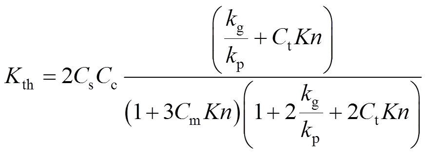
Four types of approach have been made to theoretically study thermophoresis. Among them, the equation derived by Brock [4] was more widely used because of their simplicity in calculating thermal force or thermophoretic velocity. The expression for thermal force near a continuum limit is [4]

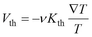
this a dimensionless factor called thermophoretic coefficient and defined by Brock as

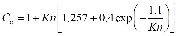
The Cunningham slip correction factor,c, was given by Hinds (1982), as follows:
Thermophoresis effect was reviewed by some researchers including Bakanov [6], Lee and Kim [7], Li and Davis [8, 9], and Talbot[5]. Theoretical study of thermophoretic deposition of aerosols in tube or pipe flows was investigated by several groups such as Butchelor and Shen [10], Chiou [11], He and Ahmadi [12], Lin and Tsai [13], Stratmann. [14], and Walker[15]. For all related works, the system was a cooled laminar flow with the local thermal gradient decreasing in the flow direction. Thermophoretic deposition of particles’ flow in an annulus was studied theoretically by Fiebig. [16] and Weinberg [17]. They considered particle deposition only by thermophoresis and using Eulerian method. Chang. [3] carried out experiments and also numerical simulations (Eulerian method) to quantify thermophoretic deposition in an annular flow system with fixed thermal gradients between two concentric cylinders.
These previous theories on thermophoretic deposition in laminar annular flow are only restricted to the fully developed flow, and the entrance flow effect had rarely been investigated. Recently, Lin and Tsai [13] found that the gas collection efficiency in a long tube is higher for developing flow than fully developed flow.
When flow is fully developed, the analytical velocity distribution is available [18] and the developing temperature profile can be numerically solved to obtain the critical particle trajectory and thermophoretic deposition efficiency. However, when both flow and temperature are developing, there is no analytical equation for the velocity and temperature field. In this study, developing velocity field was simulated numerically by the semi-implicit method for pressure- linked equations (SIMPLE) algorithm [19]. Hence, the obtained velocity distribution was used to calculate the developing temperature profile numerically, and then the critical radial position and deposition efficiency was obtained by solving the particle equations of motion.
2 GOVERNING EQUATIONS
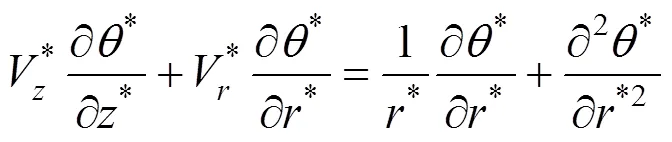
2.1 Velocity and temperature profiles
The system under investigation, as depicted in Fig. 1, involves incompressible and laminar flow of a hot gas containing suspended aerosol particles in an annulus with the two concentric cylinders at constant wall temperature.
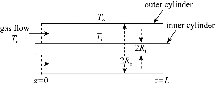
Figure 1 Schematic of the physical configuration of the investigated system
2.1.1
The steady state momentum balance for a fully developed, laminar and incompressible fluid flowing through the annular region between two coaxial circular cylinders has been solved and presented by Bird[18]. The solution for velocity is,
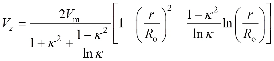
whereis the ratio of inner to outer radius of the cylinders andmis the bulk mean velocity.
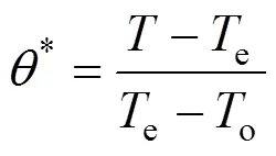
When the flow is fully developed, the temperature could still be developing when there is a sudden temperature jump in the annulus walls. Explanatorily assume the gas enters with a uniform particle concentration and temperatureeand flow through an annulus with both wall temperatures equal toe. At some distance far enough downstream such that the flow is fully developed, the wall temperatures are decreased suddenly toiando, which are different frome. This creates a “temperature jump” and the temperature field will start to develop from there [13]. The developing temperature gradient in the radial direction is higher near the position of temperature jump, and the deposition efficiency is then expected to be higher than in the fully developed case.
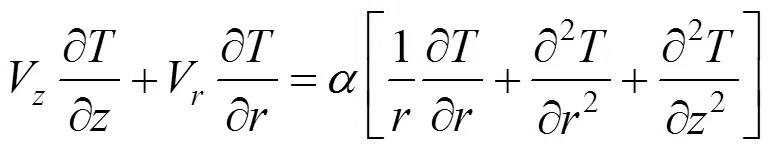
Equation (5) is used to calculate the developing temperature field numerically by solving the 2-D cylindrical energy equation:
SinceVis equal to zero in a fully developed flow, Eq. (6) is reduced to
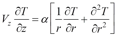
with boundary conditions,

In writing Eq. (7) we have ignored the axial conduction of heat. This will be a good approximation if let the Peclet number,, be about 100 or greater [17].
Equation (7) can be non-dimensionalized assuming all relevant physical properties are constant, as follows:
where
2.1.2
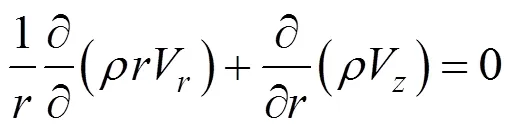
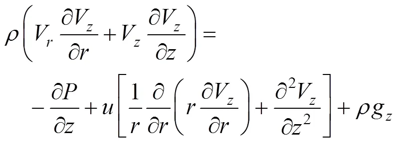
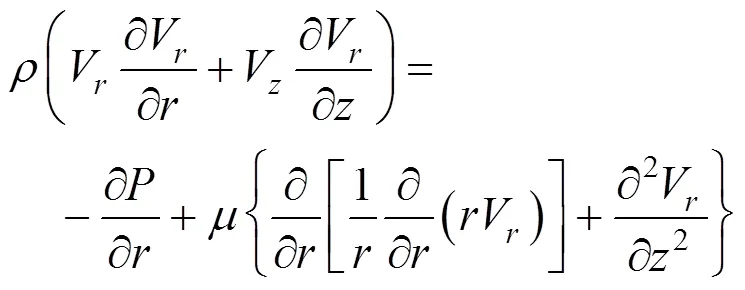
The steady state equations of continuity and momentum for a laminar incompressible fluid flowing through a circular cylinder take the following form:
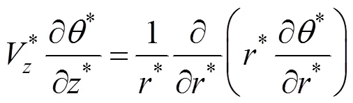
Since the axial conduction of heat is negligible relies on the fact that Peclet number is taken to be large, Eq. (6) can be reduced and non-dimensionalized as follows, assuming all relevant physical properties are constant.
with


2.2 Particle trajectory and thermophoretic deposition efficiency
The Lagrangian approach is used for predicting the trajectory of a single particle in the fluid. The Lagrangian approach predicts the trajectory of a single particle in the fluid flow as a result of various forces acting on the particle, in which the Newton’s law of motion is used to find the velocity of every particle in the flow domain. Integration of the velocity with time gives the particle trajectory.
Particle equations of motion were solved to obtain the particle trajectory and thermophoretic deposition efficiency. In cylindrical coordinates, the particle equations of motion in the(axial) and(radial) directions are
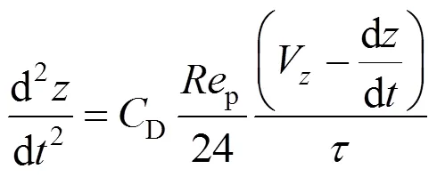

whereDis the drag coefficient and was given by Rader and Marple [20] as
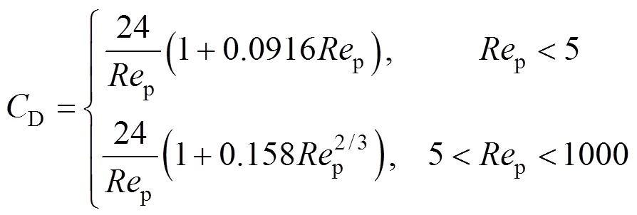
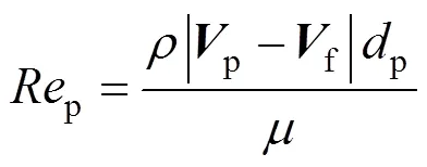
The particle Reynolds number is
Particles are assumed to be mono-disperse and spherical. In Eq. (14) the axial thermophoretic motion of particles was ignored. This assumption also relies on the fact thatis taken to be large. Since the typical particle size is about 1 µm, particle Brownian diffusion may be neglected in the bulk of the gas [17].
The first term on the right hand side of Eqs. (14) and (15) is the drag force due to relative motion between particle and fluid. The second term in Eq. (15) is the thermophoretic force. The particle equations of motion were integrated numerically through the domain of interest by Fourth-order Rung-Kutta method. It is assumed that the initial velocity of particles at the entrance is the same as the gas flow velocity at that point. The procedure is repeated until the particle hits the walls or leaves the calculation domain.
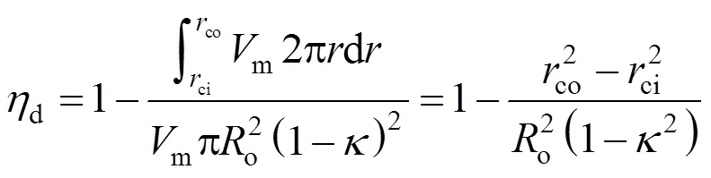
In this work, the thermophoretic deposition efficiency in an annulus was calculated for a gas flow in a concentric annulus by the critical particle trajectory method. The critical particle trajectory is shown in Fig. 2. The critical particle trajectory is defined as the one a particle starting from critical radial position,c, at the entrance, will deposit just at the end of the annulus length[13].
After obtaining the particle trajectories by solving Eqs. (14) and (15), the critical radial positions are simply found.
The thermophoretic deposition efficiency is defined as the ratio of the rate of particle deposition on the wall to the rate of particle entering the annulus, assuming particle concentration based on the particle number density, is uniform at the inlet of annulus.
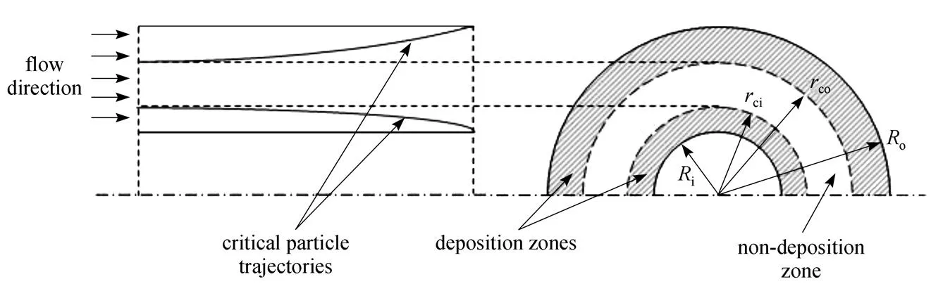
Figure 2 Critical particle trajectory
For fully developed flow, the velocity profile (V) is calculated by Eq. (5) and therefore the deposition efficiency can be obtained by analytical integration of
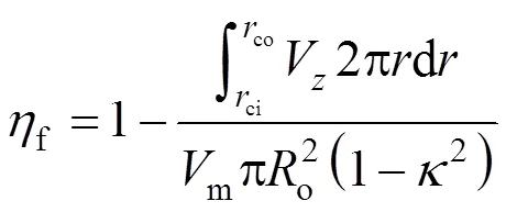
For developing flow, the velocity field is assumed to be uniform at the entrance of the annulus, and therefore the efficiency of thermophoretic deposition can be calculated as
2.3 Numerical procedure
For the numerical solution, the governing Eqs. (10) to (12) are discritized using finite volume method (FVM) [19]. The velocity components are defined on staggered grids and the other dependent variables are located at the nodal points of the main grid.
The grid is non-uniform in the-direction within the domain, with the grid spacing reduced as one moves toward the inlet of the tube. There is also a refined grid region in the-direction, adjacent to the walls. The grid spacing is larger far from the entrance region, where the flow does not vary considerably. The main grid is shown in Fig. 3.
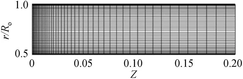
Figure 3 Schematic of the main grid used to calculate the flow field
The simultaneous numerical solution of Eqs. (10) to (12) by means of the SIMPLE algorithm provides the developing velocity field which was used to calculate the developing temperature field numerically by solving the 2-D cylindrical energy equation in form of Eq. (6).
The governing equation of energy balance is solved on the same non-uniform grid.
In the finite volume method, using smaller meshing yields more accurate results but longer calculating time. To optimize the size of meshing, we investigated 3 different mesh sizes: 30×50, 50×100 and 70×200. Low accuracy and divergences of the results was seen for the first coarse mesh and long time of calculating on the third finer one. So the optimum meshing was chosen as 50×100 for the condition of this study. In addition the dimensional radius and length of the domain are 1 cm and 10 cm respectively.
3 RESULTS AND DISCUSSION

The numerical solution of developing temperatureis compared with analytical solution presented by Kakac. [21] in Fig. 4. Kakac. have estimated the fluid bulk mean temperature or “mixing cup”,m, for a finite number ofand dimensionless axial distance:
wherecis the cross section area of the annulus. Good agreement indicates that the present simulation is accurate.

—— Kakac.;▲ this study
The validity of the numerical solution was checked by comparing simulation result with analytical one previously published by Weinberg [17] for a fully developed annular flow as shown in Fig. 5, considering particle deposition only by thermophoresis. The results are shown to be in a good agreement with that simulation since the percent deviation is less than 5%.
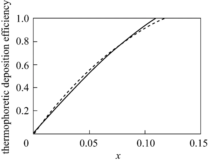
Figures 6 and 7 show the effect of entrance region (developing flow) on particles trajectory for two various particle diameters. It can be seen from these figures, the thermophoretic deposition of particles is more for developing flow than fully developed flow. In the other hand, one can see for both cases, more smaller particles are deposited near the inlet of annulus.
this study; —— Weinberg
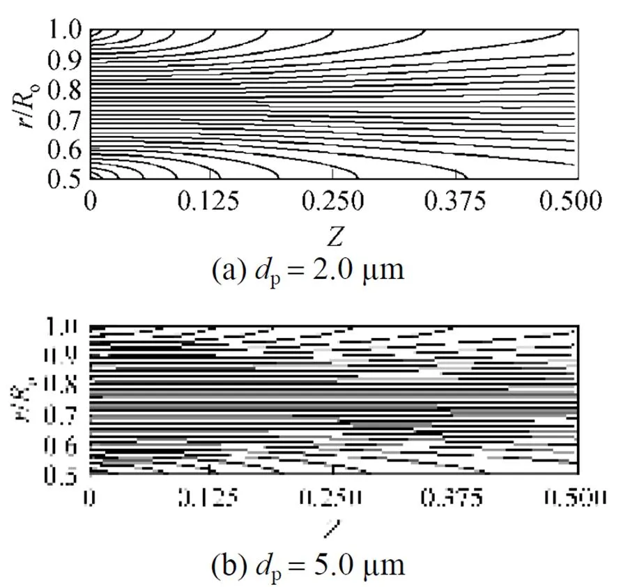
Figure 6 Particles trajectory for developing flow at=0.5and=1.0
Figure 7 Particles trajectory for fully developed flow at=0.5 and=1.0


Small particles were found deposited more easily near the position of temperature jump or inlet of annulus. It should be noted that smaller particles receive a more remarkable thermophoretic effect than larger ones, since decreasing the particle size will decrease the particle relaxation time and particle inertia, so that it will response faster to the fluid flowing variations.


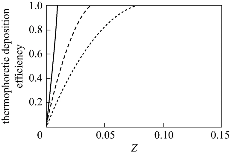
According to Figs. 8 to 13, in all cases almost 100% collection might be easily realized.
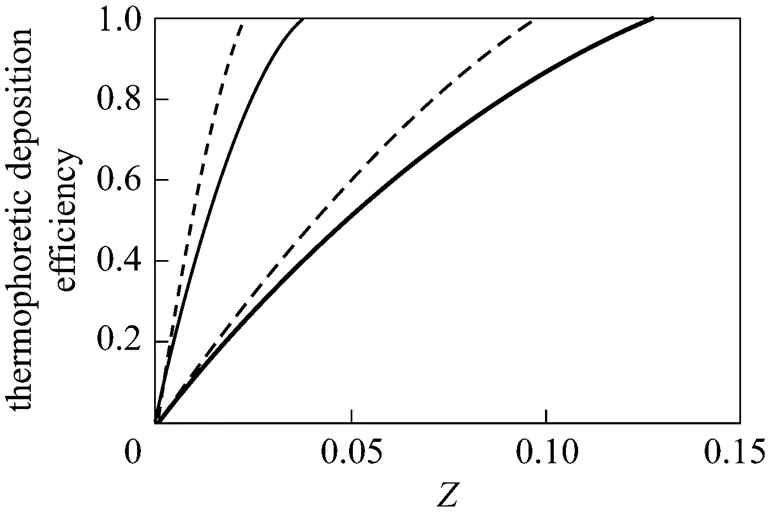

10, developing;10, fully developed

In addition, one can observe the effect of developing flow in an annulus on thermophoretic deposition efficiency by comparing Figs. 8, 10 and 12 for fully developed flow with Figs. 9, 11 and 13 for developing flow.
4 CONCLUSIONS
The thermophoretic deposition efficiency for a model system is studied where gas flows in an annular region between two concentric cylinders. It was shown that, by maintaining the temperature gradient in the gas, complete deposition may be readily achieved. The results of present work indicates that for increasing the thermophoretic deposition efficiency, one would need a higher thermal gradient, longer deposition distance, larger tube radius ratio or smaller particle diameter. Furthermore, it is found that by taking into account the effect of developing flow at the entrance region, higher deposition efficiency is obtained than fully developed flow.
NOMENCLATURE
dynamic mobility [c/(3πp)]
cCunningham slip correction factor
Ddrag coefficient
mmomentum exchange coefficient
sthermal slip coefficient
ttemperature jump coefficient

pparticle diameter, m
ththermophoretic force, N
ththermophoretic coefficient
ggas thermal conductivity, W·m-1·°C-1
pparticle thermal conductivity, W·m-1·K-1
annular length, m
pmass of particle, kg

gas Reynolds number
pparticle Reynolds number
iinner tube radius, m
oouter tube radius, m
radial coordinate, m
ccritical radial position, m
egas temperature at the entrance of annulus, K
iinner tube temperature, K
oouter tube temperature, K
wwall temperature (defined aswoi), K
mbulk mean velocity of gas, m·s-1
Vgas velocity (-component), m·s-1
ththermophoretic velocity
Vgas velocity (-component), m·s-1
axial coordinate, m
gas thermal diffusivity, m2·s-1
dthermophoretic deposition efficiency for developing flow
fthermophoretic deposition efficiency for fully developed flow
gas mean-free-path, m
gas dynamic viscosity, kg·m-1·s-1
gas kinematic viscosity, m2·s-1
1 Walsh, J.K., Weimer, A.W., Hrenya, C.M., “Thermophoretic deposition of aerosol particles in laminar tube flow with mixed convection”,.., 37, 715-734 (2006).
2 Zheng, F., “Thermophoresis of spherical and non-spherical particles: A review of theories and experiments”,.., 97, 255-278 (2002).
3 Chang, Y.C., Ranade, M.B., Gentry, J.W., “Thermophoretic deposition in flow along an annular cross-section: Experimental & simulation”,.., 26 (3), 407-428 (1995).
4 Brock, J.R., “On the theory of thermal forces acting on aerosol particles”,.., 17, 768-780 (1962).
5 Talbot, L., Cheng, R.K., Schefer, R.W., Willis, D.R., “Thermophoresis of particles in a heated boundary layer”,.., 101 (4), 737-758 (1980).
6 Bakanov, S.P., “Future directions for experiments in thermophoresis: A commentary”,.., 26, 1-4 (1995).
7 Lee, W., Kim, S.S., “Thermophoresis in the cryogenic temperature range”,.., 32, 107-119 (2001).
8 Li, W., Davis, E.J., “Measurement of the thermophoretic force by electrodynamic levitation: Microspheres in air”,.., 26, 1063-1083 (1995).
9 Li, W., Davis, E.J., “The effects of gas and particle properties on thermophoresis”,.., 26, 1085-1099 (1995).
10 Butchelor, G.K., Shen, C., “Thermophoretic deposition of particles in gas flowing over cold surface”,.., 107 (1), 21-37 (1985).
11 Chiou, M.C., “Random eddy model for prediction of thermophoretic effects on particle deposition processes”,....., 17 (3), 21-37 (1996).
12 He, C., Ahmadi, G., “Particle deposition with thermophoresis in laminar and turbulent duct flows”,.., 29, 525-546 (1998).
13 Lin, J.S., Tsai, C.J., “Thermophoretic deposition efficiency in a cylindrical tube taking into account developing flow at the entrance region”,.., 34, 569-583 (2003).
14 Stratmann, F., Otto, E., Fissan, H., “Thermophoretic and diffusional particle transport in cooled laminar tube flow”,.., 25 (7), 1305-1319 (1994).
15 Walker, K.L., Homsy, G.M., Geyling, R.T., “Thermophoretic deposition of small particles in laminar tube flow”,.., 69 (1), 138-147 (1979).
16 Fiebig, M., Hilgenstock, M., Riemann, H.A., “The modified chemical vapor deposition process in a concentric annulus”,.., 9, 237-249 (1988).
17 Weinberg, M.C., “Thermophoretic deposition of particles in laminar flow in concentric annulus”,...., 66 (6), 439-443 (1983).
18 Bird, R.B., Stewart, W.E., Lightfoot, E.N., Transport Phenomena, Wiley, New York (1960).
19 Patankar, S.V., Numerical Heat Transfer and Fluid Flow, McGraw-Hill, New York (1980).
20 Rader, D.J., Marple, V.A., “Effect of ultra-Stokesian drag and particle interception on impaction characteristics”,.., 4, 141-156 (1985).
21 Kakac, S., Shah, R.K., Aung, W., Handbook of Single-Phase Convective Heat Transfer, Wiley, New York (1987).
2008-08-03,
2009-06-14.
* To whom correspondence should be addressed. E-mail: a.soltani@mail.uk.ac.ir; fsolti@yahoo.com
 Chinese Journal of Chemical Engineering2009年5期
- Chinese Journal of Chemical Engineering的其它文章
- Molecular Simulation of CO2/H2 Mixture Separation in Metal-organic Frameworks: Effect of Catenation and Electrostatic Interactions*
- Deactivation Kinetics of Nitrile Hydratase in Free Resting Cells*
- Corrosion Behavior of TP316L of Superheater in Biomass Boiler with Simulated Atmosphere and Deposit
- Influence of A-type Zeolite on Methane Hydrate Formation*
- Effects of Sintering Atmosphere on the Microstructure and Surface Properties of Symmetric TiO2Membranes*
- Improvement of Isomerization Process of Crude Isoamylene with Tertiary-amyl-alcohol Addition