
染料敏化太阳能电池用聚偏氟乙烯 /丙烯酸酯互穿网络基凝胶聚合物电解质的制备与性能表征
2010-05-05 22:55杨艳陶杰金鑫秦琦
杨 艳 陶 杰 金 鑫 秦 琦
(南京航空航天大学材料科学与技术学院,南京,210016,中国)
INTRODUCTION
Dye-sensitized solar cells (DSSCs) are becoming a promising alternative to classical photovoltaic devices based on inorganic semiconductor technology because of their possible low production cost and the expected high energy conversion efficiency[1].DSSCs with liquid electrolyte have reached the efficiency of as high as 11.04%[2].However,the disadvantages of easy evaporation and solvent leakage reduce the long stability of DSSCs.
To solve these problems,alternative robust sealing methods,replacementofthe volatile solvents with ionic liquid[3-4], organic and inorganic hole-transport materials[5-6], nanocomposites[7-8], solid, and quasi-solid state polymer electrolytes[9-10]have been attempted.Gel polymer electrolytes(GPEs)are constructed by trapping liquid electrolytes,which usually contain organic solvents(PC,EC or CAN)and inorganic salts,such as LiI,NaIand KI.GPEs possess low vapor pressure,excellent contacting and filling properties between nanostructured electrode and counter electrode, higher ionic conductivity compared with theconventional polymer electrolytes and excellent thermal stability. Therefore, GPEs have attracted intensive attentions and found their wide application in DSSCs[11-16].
It is known that poly(vinylidene fluoride)(PVDF)is photochemically stable even in the presence of TiO2and Pt nanoparticles and acrylate has good solvent retention.In 2001,Rajendran,et al[17]reported an electrochemical investigation on poly (methylmethacrylate)(PMM A )/PVDF blend-based polymer electrolytes for the applications in lithium batteries. The higher conductivities were observed in the polymer membranes result from the lowerdegree ofcrystallinity. Ourteam investigates the performance of DSSCs employing a quasi-solid polymerelectrolytes based on PVDF-PMM A blend polymer[18].
Interpenetrating polymer network(IPN)is a special kind of polymer blend.It can be defined as a combination of two polymers in network form,one of which is synthesized and/or cross-linked in the immediate presence of the other.It can be distinguished from blend polymer in two ways:(1)IPN swells,but does not dissolve in solvents;(2)Creep and flow are suppressed in IPN.IPN may be made from polymer(1),which can hold liquid electrolyte and exhibit high ionic conductivity, and polymer (2), which is mechanically and electrochemically stable to electrodes.T C Wei,et al[19]prepared a crosslinking film of PVDF-HFP/PEG/PEGDM A electrolyte with excellent mechanical strength even at 10 μ m thickness.DSSC equipped with thispolymerelectrolyte showsa conversion efficiency over 4% under 100 mW/cm2illumination.To our knowledge,there are not too many reports about polymer electrolyte based on PVDF/acrylate blend or IPN applied in DSSCs.
In this paper,a micro-phase separation type GPE based on IPNs of cross-linked acrylate is synthesized.This is a special kind of polymer electrolyte,which lies between the chemically cross-linking gelled polymer electrolyte and the porous polymer electrolyte.They can swell with more liquid electrolyte solution than the ordinary porous solid-state electrolyte because ofthe strong interaction of electrolyte solution and one of the interpenetrating components[20]. In the paper,polymer membrane is prepared with more pores by the phase inversion process and their swelling and diffusion characteristics are studied by changing polymer composition or different cross-linking monomers. Moreover, the differences between blend polymer network(BPN)and IPN are studied, thus providing helpful reference in selecting and designing of polymer electrolyte for DSSCs.
1 EXPERIMENT
1.1 Preparation of GPE
1.1.1 BPNs PVDF/PMMA(I)
The dry porous polymer membrane composed of PVDF(SOLEF 1015)and PMMA(Mw=200 000)is synthesized by the phase inversion process.The dried polymer powders of PVDF and PMM A are dissolved in N, N-dimethylformamide (DM F). An amountof propanetriol as nonsolvent is then added under continuous stirring at 60°C for 12 h to form homogeneous hybrid. The resulting viscous mixture spread on a glass substrate is heated to 80°C for 24 h to remove solvent and nonsolvent.
1.1.2 IPNsPVDF/PMMA(Ⅱ )or PVDF/PEGDMA(Ⅲ)
The dried polymer powders of PVDF and propanetriol are dissolved in DMF.The acrylate monmers, methylmethacrylate (MMA) or ethylene glycol dimethacrylate (EGDM A,Aldrich),are then added into the gel solution undercontinuousstirring at50°C to form homogeneous hybrid.Finally,a small amount of initiator,2,2′-azobisisobutyronitrile(AIBN)is added in the solution. The resulting viscous mixture spreading on a glass substrate is heated to 80°C for 24 h to ensure polymerization of acrylate monmers and to complete phase inversion process.
In these films preparation,the weight ratios ofPVDF/acrylate polymer mixtures are 8/2,7/3,6/4,and 5/5,respectively.The thickness of the polymer electrolyte membranes is approximately 100 μ m. The formed film is washed in ethanol to extract residual propanetriol. Finally, the dried polymer membranes are soaked in liquid electrolyte(0.5 mol/L NaI,0.05 mol/L I2,0.1 moL/L 4-tertbutylpyrdine in the binary organic solvent mixture propylene carbonate and ethylene carbonate with 4∶6(in weight))for 12 h to obtain the desired GPEs.
1.2 Preparation of TiO2photoanode
Self-aligned highly ordered TiO2nanotube arrays are fabricated by potentiostatic anodic oxidation in a two-electrode electrochemical cell[21]. The separation distance between the electrodes is 4 cm.The voltage applied between Ti-foil anode and Pt cathode is 20 V at the room temperature. The used electrolyte is ethylene glycol solution with an addition of H2O(1% in volume)and NH4F(0.25% in weight). All solutions are prepared from reagent grade chemicals.Prior to anodization,all the Ti-foil samples are cleaned with acetone and ethanol,chemically polished to a mirror image by the polishing solution,and then rinsed with distilled water and dried in nitrogen stream.Only one face of the Ti-foil is exposed to the electrolyte during anodization by tape-masking the other face.TiO2nanotube arrays having lengths up to 20μ m are grown in vertical direction to the underlying Tifoil with an exposed area of 0.25 cm2.
The as-prepared nanotube Ti-foil is thoroughly washed with distilled water.Then they are crystallized into anatase phase after annealing at 450°C for 3 h in oxygen atmosphere because as-anodized TiO2nanotubes are amorphous phase.
1.3 Assembly of DSSCs
The TiO2film is immerged in a 0.5 mmol ethanol solution of cis-[(dcbH2)2Ru(SCN)2](N719;Solalonix)for 24 h to absorb the dye adequately,and the other impurities are washed up with anhydrous ethanol and dried in moisturefree air.After that,a dye-sensitized TiO2film is prepared.
A quasi-solid-state DSSC is assembled by sandwiching a slice ofGPE between a dye sensitized TiO2electrode and a platinum counter electrode(purchased from DYSEOL).The two electrodes are clipped together with clamps.For comparison, DSSC with conventional liquid electrolyte is also assembled.The active area of the cell is 0.25 cm2.
1.4 Measurement
The IR absorption spectra are taken using an attenuated totalreflection Fourier transform infrared(FFIR)spectrometer(PerkinElmer1760)over the range from 600 cm-1to 4 000 cm-1.The morphology of polymer membrane is characterized by scanning electron micrograph(Quanta 200,FEI).
The electrolyte uptake is calculated by

where Wiand W0are the weights of the wet and dry membranes,respectively.
The porosity of membranes is measured by immersing the membranes into n-butanol for 1 h.The porosity is calculated using the following equation[22]

where Mpis the weight of membrane,Mbthe weight of absorbed n-butanol,dpthe density of the membrane and dbthe density of n-butanol,respectively.
The symmetric cell is built to characterize electrochemical properties of electrolyte with a similar design as DSSC by sandwiching the GPE sample between two Pt electrodes (Pt/electrolyte/Pt).The electrolyte resistance Rbis measured using CHI660 electrochemical workstation in the frequency range from 10-2to 105Hz with amplitude of5 mV. The ionic conductivity of the GPE is calculated with

where d is the thickness of electrolyte and S the area of electrolyte.
To investigate the diffusion coefficients of I3-in the electrolyte,steady-state voltammograms of GPE is performed.The system is polarized from 0 V to 1 V at a rate of 10 mV/s.The apparent diffusion coefficients of triiodide(D)can be calculated according to the equation[23]

where Ilimis the limiting current density,n the electron number per molecule,d the thickness of gel electrolyte,F the Faraday constant and C the bulk concentration of electroactive species.
Photocurrent-voltage characteristics of DSSCs are obtained by a Keithley model 2400 digital source meter using an Oriel 91192 solar simulatorequipped with AM 1.5 filterand intensity of 100 mW/cm2.The fill factor and the conversion efficiency(Z)of the cell are calculated by the following equations[24]

where Iscis the short-circuit current density;Voc the open-circuit voltage;Pinis the incident light power;Impand Vmpare the current density and voltage in the photocurrent-voltage curves,respectively,at the point of maximum power output.
2 RESULTS AND DISCUSSION
2.1 FTIR spectroscopy
The chemical compositions for the prepared polymer membranes are analyzed using FTIR spectroscopy (see Fig.1). The characteristic peaks of PVDF at 838,877,1 074,1 172,1 232 and 1 406 cm-1are observed for all the samples.The samples show that sharp lines at 1 725,1 148 cm-1correspond to C= O and C-O-C stretching vibration bands of acrylate polymer[25].No peaks observed at 1 640 cm-1indicate that the C= C bond in uncross-linked acrylate monmer disappeares via cross-linking when the membrane is prepared[26].FTIR spectra confirm that both PVDF and PMMA or PEGDMA are presented in the polymer membrane.

Fig.1 FTIR spectra of polymer membranes
2.2 Morphology
Fig.2 shows typical SEM images of the polymer membranes with different systems.All membranes display a surface with a homogeneous porosity.The interior of the membrane has a uniform porous structure as well as the exterior.This indicates that the cellular pores are all open with extensive pore-pore interconnections.
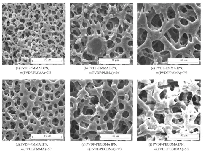
Fig.2 SEM images of dry polymer membranes
For the PVDF-PMMA blend system,there are many small nodular entities protruding out of the pore wall,which are more likely to be PMM A particles separating from the polymer host[27].The size and the amount of the nodular textures increase with the increase ofthe amount of PMMA.It can infer that solid-solid demixing has occurred in addition to liquid-liquid demixing or crystallization phase separation process[28].On the contrary,no obvious nodular textures are found in both PVDF-PMM A and PVDFPEGDMA IPN membranesowing to better compatibility between PVDF and interpenetration acryate polymer.The size and the amount of the pores decrease with the increase of the amount of acryate polymer for the IPN system.It can be explained that more cross-links result in denser network structure.
2.3 Porosity and electrolyte uptake
The electrolyte uptake is found to depend on the porosity of the polymer membranes in the paper.According to Saito,et al[29],the porosity,one ofthe importantparameters ofporous polymer membranes,can dominate the conduction properties ofthe carriers. Thus,n-butanol absorption technique isused to measure the porosity of the polymer membranes.In Fig.3,the maximum of the porosity is observed when the weight ratio of PVDF/acrylate polymer is 7/3 for all systems.These results indicate that the size of the macrovoids can be controlled by adjusting the acrylate polymer content.Compared with PVDF/PMMA BPN and PVDF/PEGDM A IPN,PVDF/PMMA IPN gives a distinct decrease in porosity. PVDF/PMMA IPN shows denser network structure than other two systems because MM A has higher reactivity and results in highly ordered and regular patterned networks.The highest porosity of 45.7% is measured in PVDF/PEGDMA IPN,which is attributed to a very low and smooth crosslinked network structure of the membrane.
The tendency of the electrolyte uptake is similar to that of porosity(see Fig.4).GPEs with 30%(in weight)PEGDMA and 70%(in weight) PVDF hasthe maximum electrolyte uptake 261.1%. According to Saito and coworkers[30],there are two distinct steps for liquid electrolyte uptake in PVDF-based porousgel polymer membranes. Firstly, the liquid electrolyte occupiessome pore spaces ofthe membrane. Then, those electrolytes in pores penetrate and swell the polymer chains to form the gel.
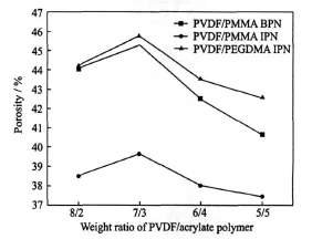
Fig.3 Porosity of polymer membranes

Fig.4 Electrolyte uptake of polymer membranes
2.4 Ionic conductivity and triiodide diffusion coefficients of GPEs
EIS is used to characterize the electrochemicalbehaviorofGPE. The ionic conductivity ofGPEs(e)and the triiodide apparent diffusion coefficient(D)of PVDF/PMM BPN,PVDF/PMM A IPN and PVDF/PEGDM A IPN are summarized,respectively in Tables 1-3.The presence of acrylate polymer can influence the conductivity in different ways. The crystallinity of the membrane is reduced with increasing of acrylate content[28],which improves the conductivity of GPEs. Meanwhile, the porosity of the membrane decreases with increasing acrylate content,leading to the drop of the conductivity of GPEs. As a result,GPE shows the highesteand D when the weight ratio ofPVDF/acrylate polymeris 7/3 and then decreases.The greatest values eand D obtained in PVDF/PEGDM A IPN are 3.02×10⁻⁴S·cm-1and 1.10×10⁻⁶cm2·s-1.

Table1 σand D of PVDF/PMMA BPN GPEs

Table2 σandD of PVDF/PMMA IPN GPEs
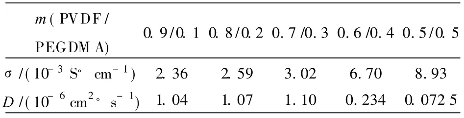
Table3 σand D of PVDF/PEGDMA IPN GPEs
2.5 Photovoltaic performance
The photocurrentperformance forDSSC with different electrolytes(A to D)are tested.The photocurrent-voltage curves are shown in Fig.5 and cell parameters corresponding to these DSSCs are summarized in Table 4. It is regrettable that the conversion efficiencies of the cells are unsatisfactory.Further improvements on device performance should be achievable through optimization of electrode preparation and the cell assembling,etc.
These results indicate that IPN worsens the cell performance to a certain extent for its denser network structure,compared with BPN composed of the same constituent in the same proportions.Selecting EGDM A as crosslinker optimizes the photovoltaic performance.This can be explained on the basis of porosity formation in the network structure of the gel and excellent compatibility with PVDF.The result accords with e and D variation law.DSSC employing PVDF/PEGDM A IPN GPE yields an open-circuit voltage of 0.674 V,short-circuit current of 8.476 m A·cm-2and the conversion efficiency of 2.710%,which is above 60% efficiency of DSSC employing liquid electrolyte,under 100 mW/cm2illumination.

Fig.5 Photocurrent-voltage curves of DSSCs fabricated of variousGPEsunder100 mW/cm2illumination

Table 4 Photovoltaic performance of DSSC
In Table 4,the quasi-solid polymer electrolyte used in Cell A is m(PVDF/PMMA BPN)=7∶3,in Cell B is m(PVDF/PMM A IPN)=7∶3,and in Cell C is m(PVDF/PEGDM A IPN)=7∶3.The liquid electrolyte in Cell D is used as a reference.
3 CONCLUSION
GPEs of PVDF/PMM A and PVDF/PEGDM A IPN are prepared.The IR absorption spectra reveal that PMM A or PEGDA is involved in the formation of IPN structure with PVDF.Morphologies indicate that PVDF is compatible with interpenetrating acrylate polymer. The higher porosity and electrolyte uptake are observed in the membranes prepared at lower crosslinker concentration.GPEs based on PVDF/PMMA IPN show lower ionic conductivity and triiodide apparent diffusion coefficient for their denser network structure,compared with PVDF/PMMA BPN.Substituting EGDM A for M AA into crosslinker significantly improves the porosity and the electrochemicalbehaviorof GPE.DSSC employingPVDF/PEGDMA IPN GPE yields an open-circuit voltage of 0.674 V,short-circuit current of 8.476 mA·cm-2and the conversion efficiency of 2.710%,which is above 60% efficiency of DSSC employing liquid electrolyte under 100 mW/cm2illumination.These are preliminary results without optimization. The optimization of many parameters for the electrode preparation and the cell assembling will be studied. The further improvement of the photovoltaic performance is expected in the near future.
[1] Gr ä tzel M.Photoelectrochemical cells[J].Nature,2001,414:338-344.
[2] Nazeeruddin M K,PechyP,Renouard T,et al.Engineering of efficient panchromatic sensitizers for nanocrystalline TiO2-based solar cells[J].J Amer Chem Soc,2001,123(8):1613-1624.
[3] Xue B,Wang H,Hu Y,et al.Highly efficient dyesensitized solar cells using a composite electrolyte[J].C R Chim,2006,9:627-630.
[4] Zafer C,Ocakoglu K,Ozsoy C,et al.Dicationic bis-imidazolium molten salts for efficient dye sensitized solarcells:synthesis and photovoltaic properties[J].Electrochim Acta,2009,54(24):5709-5714.
[5] Bandara J, Weerasinghe H. Solid-state dyesensitized solarcell with p-type NiO as a hole collector[J].Sol Energy Mater Sol Cells,2005,85(3):385-390.
[6] Xia J,Masaki N,Lira-Cantu M,et al.Influence of doped anions on poly(3,4-ethylenedioxythiophene)as hole conductors for iodine-free solid-state dyesensitized solar cells[J].J Am Chem Soc,2008,130(4):1258-1263.
[7] Huo Z P, Dai S Y, Wang K J, et al.Nanocomposite gel electrolyte with large enhanced charge transportproperties of an I3-/I-redox couple for quasi-solid-state dye-sensitized solar cells[J].Solar Energy Materials&Solar Cells,2007,91(20):1959-1965.
[8] Huang K C,Vittal R,Ho K C.Effects of crown ethers in nanocomposite silica-gel electrolytes on the performance of quasi-solid-state dye-sensitized solar cells[J].Sol Energy Mater Sol Cells,2010,94(4):675-679.
[9] Kim Y,Sung Y E,Xia J B,et al.Solid-state dyesensitized TiO2solar cells using poly (3, 4-ethylenedioxythiophene)as substitutes of iodine/iodide electrolytes and noble metal catalysts on FTO counter electrodes[J].Journal of Photochemistry and Photobiology A: Chemistry,2008,193(2/3):77-80.
[10]Li B,Lin J M,Li S Q,et al.Quasi-solid state dye sensitized solar cell-based on novel gel polymer electrolyte with poly(methyl methacrylate-coacrylonitrile)[J].Materials Review,2008,22(9):106-108.
[11]Suryanarayanan V,Lee K M,Hoc W H,et al.A comparative study of gel polymer electrolytes based on PV DF-HFP and liquid electrolytes,containing imidazolinium ionic liquids of different carbon chain lengths in DSSCs[J].Sol Energy Mater Sol Cells,2007,91(15/16):1467-1471.
[12]Lan Z,Wu J,Lin J, et al. Influence of ionic additives NaI/I2on the properties of polymer gel electrolyte and performance of quasi-solid-state dyesensitized solar cells[J].Electrochim Acta,2008,53(5):2296-2301.
[13]Bandaraa T,Dissanayakea M,Albinssonb I,et al.Dye-sensitized, nano-porous TiO2solarcell with poly(acrylonitrile):MgI2plasticized electrolyte[J].Journal of Power Sources,2010,195(11):3730-3734.
[14]Benedetti J E,Goncalves A D,Formiga A L B, et al.A polymer gel electrolyte composed of a poly(ethylene oxide)copolymer and the influence of its composition on the dynamics and performance of dye-sensitized solar cells[J]. J Power Sources,2010,195(4):1246-1255.
[15]Chen P Y,Lee C P,Vittal R,et al.A quasi solidstate dye-sensitized solar cell containing binary ionic liquid and polyaniline-loaded carbon black [J].Journal of Power Sources,2010,195(12):3933-3938.
[16]Huo Z,Zhang C,Fanga X,et al.Low molecular mass organogelator based gel electrolyte gelated by a quaternary ammonium halide salt forquasi-solidstate dye-sensitized solar cells[J].J Power Sources,2010,195(13):4384-4390.
[17]Rajendran S, Kannan R, Mahendran O. An electrochemical investigation on PM M/PV DF blendbased polymer electrolytes[J].Materials Letters,2001,49(3/4):172-179.
[18]Yang Y,Tao J,Ma L.Study on properties of quasi solid polymer electrolyte based on PVDF-PM M A blend for dye-sensitized solar cells[J].Materials Science Forum,2009,610/613:347-352.
[19]Wei T C,Wan C C,Wang Y Y.Preparation and characterization of a micro-porous polymer electrolyte with cross-linking network structure for dye-sensitized solar cell[J].Sol Energy Mater Sol Cells,2007,91(20):1892-1897.
[20]Murata K,Izuchi S,Yoshihisa Y.An overview of theresearch and developmentofsolid polymer electrolyte batteries[J].Electrochim Acta,2000,45(8/9):1501-1508.
[21]Tao H J,Tao Jie,Wang T,et al.Fabrication of selforganized TiO2nanotubes by anodic oxidation and their photocatalysis[J].Trans Nonferrous Met Soc China,2005,15(3):462-466.
[22]Chunga N K,Kwonb Y D,Kim D.Thermal,mechanical,swelling,and electrochemical properties of poly(vinylidene fluoride)-co-hexafluoropropylene/poly (ethylene glycol) hybrid-type polymer electrolytes[J].J Power Sources,2003,124(1):148-154.
[23]Kontos A G,Fardis M,Prodromidis M I,et al.Morphology, ionic diffusion and applicability of novel polymer gel electrolytes with LiI/I2[J].Phys Chem Chem Phys,2006,8(6):767-776.
[24] Gratzel M. Perspectives for dye-sensitized nanocrystalline solar cells[J].Prog Photovolt Res Appl,2000,8(1):171-185.
[25] Rajendran S,Mahendran O, Mahalingam T.Thermal and ionic conductivity studies of plasticized PM MA/PV DF blend polymer electrolytes[J].Eur Polym J,2002,38(1):49-55.
[26]Hou X,Siow K S.Novel interpenetrating polymer network electrolytes[J].Polymer,2001,42(9):4181-4188.
[27]Ruaan R C,Chou H L,Tsai H A,et al.Factors affecting the nodule sizeofasymmetric PM M A membranes[J].J Membr Sci,2001,190(2):135-145.
[28]Lin D J,Chang C L,Lee C K,et al.Preparation and characterization of microporous PVDF/PM M A composite membranes by phase inversion in water/DM SO solutions[J].Eur Polym J,2006,42(10):2407-2418.
[29]Saito Y,Stephan A M,Kataoka H.Ionic conduction mechanisms oflithium gelpolymerelectrolytes investigated by the conductivity and diffusion coefficient[J].Solid State Ionics,2003,160(1/2):149-153.
[30]Saito Y,Kataoka H,Quartarone E,et al.Carrier migration mechanism of physically cross-linked polymer gel electrolytes based on PV DF membranes[J].J Phys Chem B,2002,106(29):7200-7204.
猜你喜欢
中国机械工程(2022年21期)2022-11-21
世界科学技术-中医药现代化(2022年2期)2022-05-25
中国机械工程(2022年7期)2022-04-20
世界科学技术-中医药现代化(2021年8期)2021-12-21
世界科学技术-中医药现代化(2021年7期)2021-11-04
数据采集与处理(2021年4期)2021-09-20
西安工程大学学报(2016年6期)2017-01-15
西北工业大学学报(2015年4期)2016-01-19
物理化学学报(2015年7期)2015-12-30
材料研究与应用(2015年4期)2015-08-23
 Transactions of Nanjing University of Aeronautics and Astronautics2010年4期
- Transactions of Nanjing University of Aeronautics and Astronautics的其它文章
- 机身整体壁板在轴压载荷下后屈曲计算及结构优化
- 微型叶轮机械联合试验台设计
- 飞机除冰液对高性能混凝土抗冻性的影响
- 纳米二氧化钛吸入对小鼠肺部和血清生化指标的影响
- 航班进场调度的改进捕食搜索算法