TWO DIMENSIONAL NUMERICAL INVESTIGATION OF STOCK FLOW IN HEADBOX NOZZLE
2011-02-20 00:54KANGGuobingCHENKefuFENGYuchengLIJun
陕西科技大学学报 2011年3期
KANG Guo-bing, CHEN Ke-fu, FENG Yu-cheng, LI Jun
(State Key Laboratory of Pulp and Paper Engineering, South China University of Technology, Guangzhou 510640, China)
0 Inroduction
Paper machine speed has increased greatly during the last decades and will be increased continuously in the future. With the increased speed of paper machine, the production of paper is raised simultaneously and the quality of paper becomes very important. Of course, the quality of paper is influenced by many factors. It is widely accepted that headbox is an extremely critical part of the paper machine. The main function of the headbox is to distribute stock evenly across the width of the wire section. The formation property of paper is greatly influenced by headbox performance. The extent of the effect depends on the geometry of headbox and the headbox operation. As the Fig.1 shows, in the headbox nozzle, consisting of top and bottom lips, the stock is accelerated and leaves the nozzle outlet in the form of a plane jet. To generate a jet with the smallest possible velocity variations, feeding the nozzle from a large relative open area is important, the acceleration of the stock in the nozzle generates a pressure drop, and this will reduce local velocity defects and reduce the degree of relative turbulence. Thus a high degree of acceleration using a large nozzle contraction ratio (inlet divided by outlet cross sectional area, in Fig.1 the contraction ratio isB/b) will be positive[1]. The acceleration flow in the headbox nozzle also has a deflocculating effect. The turbulent intensity of stock in nozzle is larger with increase of speed. Turbulence generates shearing stress which can disperse fiber flocculation. The contraction ration has so much influence on jet angle (β, shows in Fig.1).The jet angle (β) is an important parameter, which determines the
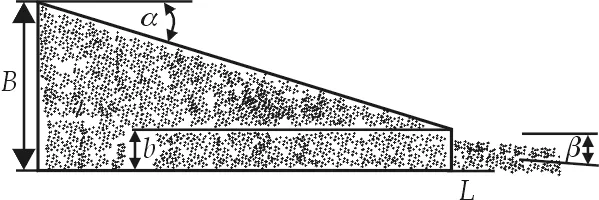
Fig.1 Geometry of headbox nozzle
point and direction of jet impingement upon the forming wire, the initial drainage and other properties of paper such as strength and fiber orientation. It has long been known that the jet angle is influenced by the contraction ratio and the ratio ofL(the bottom lip projection) tob(the distance between bottom slice and top slice). The incorrectL/bratio will cause many faults in paper or problems in forming such as holes, stock sticking to wire[2].
Many experts have investigated the relation between jet angle andL/b, contraction ratio of slices. The relation may be determined from equations that are derived from potential flow theory[3].But these equations are too complex to solve. Kerekes (1981) get other equations which were obtained by calculating a grid of data points from the potential flow equations and then fitting empirical equations to these data. The equations are somewhat complex, but suitable for use in programmable calculators and computer control of headbox[4]. But the equations only include three examples of contraction ratio degree(10°, 45°,90°). The equation ofβis shown as equation (1):
(1)
Where:X=L/bandY=b/B,0≤X≤5.0, 0≤Y≤0.95, forα=45°andα=90°, 0≤X≤5.0, 0.7≤Y≤0.90, forα=10°.
The present study investigates the flow through the converging zone of headbox and the outflow at the lip of headbox-based CFD. With the assumption of uniform grid spacing and 2-dimensional flow, a commercial computer code (Fluent) is used to study jet angle at different contraction ratio andL/b. The object is to get the function relation between the jet angle and contraction ratio andL/b. The other object of this study is to get the relation between pressure distribution in nozzle and geometry of the nozzle.
1 Numerical Simulation
1.1 Theory
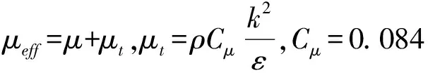
A variety of numerical methods have been developed to model and simulate turbulent flow. Three categories can be distinguished: Direct Numerical Simulation (DNS), Large Eddy Simulation (LES) and Reynolds Averaged Navier-Stokes (RANS). Turbulent flows are characterized by eddies with a wide range of length and time scales. The largest eddies are typically comparable in size to the characteristic length of the mean flow. The smallest scales are responsible for the dissipation of turbulence kinetic energy[5]. The problem with DNS of turbulent flows is that you have to simulate (or resolve) all these scales and in three dimensions. A major limitation of DNS is that most of the computational effort is spent on solving the smallest dissipative scales, which do not contribute directly to the mean flow. Since only the mean quantities are of interest in almost all practical applications, DNS remains a research tool generally used to calibrate models based on other approaches. LES is to resolve the large scales of turbulence and model the effect of the smaller scales (smaller scales are universal) by adding a sub-grid viscosity. LES is still expensive for real engineering applications[6]. RANS reduces the dynamic range of scales by averaging the instantaneous equations. It describes the evolution of averaged quantities and only resolves the mean flow field. RANS is extensively used in engineering simulations because it is less demanding computationally and it can be applied to complex configurations and operating conditions. It can provide very useful and comparatively accurate, affordable engineering solutions[7,8]. The present paper takes the RNGk-εturbulence model to simulate the converging zone of headbox. The RNGk-εmodel was derived using a rigorous statistical technique, can be described by the Navier-Stokes Equation (2).
(2)
1.2 Simulation
We consider here the turbulent flow of a homogeneous, viscous, incompressible fluid with constant properties. Geometry of converging zone of headbox is shown in Fig.2.βis the angle of outflow relative to the bottom lip of the slice,bis the distance between top lip and bottom lip,Lis the bottom lip extension,Bis the depth of flow just upstream of lice, andαis the angle of top lip relative to bottom lip.
In simulation analysisbwas 15 mm,Bwas 60 mm,Lvaried from 0 to 30 mm (L/b=0~2.0), and the range ofαwas 10°~50°. The consistence of fiber in headbox is usually below one percent. Contrasting to the geometry of headbox such as profile bar projection, nozzle angle, jet angle, bottom lip inclination angle, other factors which are less significant are: stock acceleration due to gravity, density, and viscosity. Considering the fact that the rheology of low consistency fiber water mixture is very similar to that of water, we chose water as working fluid to simulate[9]. The gravity was not taken into account. All the solid model geometries used in this paper are created with the UG-NX4 soft-ware, and their corresponding meshes are generated by ICEM-CFD. The computer code used is Fluent 12.01 and the second-order upwind scheme is employed. About the turbulence parameter, we assumed the turbulence intensity to be 2%. Mesh sensitivity studies were carried out, allowing a grid-independent solution to be established. For the case ofα=20°, the coarse mesh consists of a total of 3 550 elements. The medium mesh consists of a total of 5 370 elements. The fine mesh consists of a total of 7 210 elements. The difference in velocity of outflow between medium and fine is less than 1%. Therefore all the studies were performed using the fine mesh and all results presented here were also obtained using the fine mesh. During iteration process, when the residual error is less than 10-4.
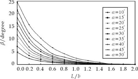
Fig. 2 Relationship between β and L/b during iterations
2 Results and Discualtion
2.1 The relationship between β and L/b, α
Fig.2 shows relationship betweenβandL/bat differentα. Fig.3 is provided by David Wood[10]in 1995. There is some difference between the results of David Wood′s research and this article. That is because the two geometries are different. In David′s research, there is a abrupt contracting up lip at the top lip, which strengthens the contracting function of the lips, and increases the turbulent intensity and the jet angle at the same time. From Fig.2 and Fig.3, we can see that the trend ofβis similar.βincreases with the increasing of contraction ratio of up lip and decreasing of ratio ofL/b. According to sensitivity ofβto the ratio ofL/b, theL/bcan be divided into three zones:L/b<0.8 high sensitive,0.8

Fig.3 Relationship between jet angle and lip geometry(with a profile bar slice variant)

Tab. 1 Coefficient of A, B, C
From curves in Fig.3, we can regress an approximate equation to show the relation betweenβandL/b, at differentα, shown as equation (3):
β=A×e-x/B+C
(3)
Wherexis the value ofL/b,A,B,Care coefficients which are related toα, shown in Tab.1.
2.2 Pressure distribution in headbox nozzle
As mentioned above the acceleration of the stock in the nozzle will lead to static pressure header turn into dynamic pressure header. This generates a static pressure drop, and reduce local velocity defects and reduce the degree of relative turbulence. The static pressure dropping is shown in Fig.4.

Fig.4 Pressure distribution in headbox nozzle
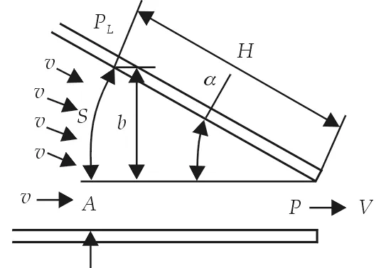
Fig.5 Sketch of pressure distribution in nozzle
Fig.4 shows the constant pressure line in nozzle is like an arc, but near the bottom it can be considered as a line. The arc and line is shown as “S” and “A” in Fig.5.
From Fig.5 the equations can be got:
(4)
According to Bernoulli theorem:
(5)
Combine the equation (4) and equation (5):
(6)
Where:PL,P-pressure, N/m2;ρ— density of stock,kg/m3;g— gravity, m/s2;V-velocity,m/s.
It can be deduced a conclusion from the equation (6) that the pressure increases rapidly from lip to inside of headbox, especially in the zone near lip, and the the pressure increases slowly, showed in Fig.6.

Fig.6 Sketch of pressure distribution in nozzle
Just consider the equation (6), it is possible in some zonePL The jet angleβincreases with the increasing of contraction ratio of up lip, and increases with decreasing of ratio ofL/b. According to sensitivity ofβto the ratio ofL/b, theL/bcan be divided into three zones: high sensitive, medium sensitive and low sensitive. It isn′t advisable to located theL/bin the zone of low sensitive of high sensitive. From the result of simulation the reasonable value ofL/bis between 0.8 and 1.2. The exponential relation between the jet angle and theL/bwas obtained from the numerical results of the present study. The function isβ=A×e(-x/B)+C, wherexis the value ofL/b,A,BandCare constants which are depended on the contraction ratio. The pressure increases increase rapidly from lip to inside of headbox, especially in the zone near lip, and the the pressure increases slowly. In theory, there can be a zone of negative pressure in nozzle, but in fact it scarcely exists in nozzle of headbox. [1] Hannu Paulapuro. Papermaking, Part 1 Stock Preparation and Wet End (Second Edition)[M]. Helsinki University of Technology, Finland,2008:212-213. [2] Appleton,Wis. Fundamentals of paper machine[J]. Tappi, 1954,37(11):488-494. [3] TAPPI Technical Information Sheets. TIS 014-2, TIS 014-3, TIS-4[Z]. Tappi, Atlanta, Ga.,1968. [4] R.J.Kerekes, E.B.Koller.Equations for calculating headbox jet contraction and angle of outflow[J]. Tappi Jaunary, 1981,64 (1):95-96. [5] F.Gao and E.E. O′Brien. A Large-Eddy simulation scheme for turbulent reacting flows[J]. Phys. Fluids,1993,(5): 1 282-1 284. [6] A.J. Chandy, D.J. Glaze, S.H. Frankel. Assessment of subgrid-scale mixing models for large eddy simulation using the filtered density function approach[C]. Proceedings of Fourth Joint Meeting of the U.S. Sections of the Combustion Institute, Philadelphia,2005. [7] Zhang Zhaoshun, Cui Guixiang, Xu Xiaochun. Large Eddy Simulation of Turbulent Flow Theory and Application[M]. Tsinghua University Press,2008: 54-59. [8] V. Singh. Study of turbulence-radiation interactions using LES of planar channel flow[D]. The Pennsylvania State University, Department of Mechanical Engineering, University Park,,2005. [9] Hye Jung youn, Hak Lae Lee. A numerical study of flow behaviour in the turbulence generator of headboxs[J]. Appita Journal, 2005,58:196-201. [10] David Wood. Headbox control developments[J]. Paper Technology,1995,(6):34-38. [11] Liu Jianan. Study on mechanism of liquid filled & air-cushioned headbox and design[D].South China University of Technology,1992.3 Conclusion