
Numerical Simulation on New Perforator
2011-07-25 06:22YAOZhihua姚志华WANGZhijun王志军LIDezhan李德战FUMeng付盟
Defence Technology 2011年4期
YAO Zhi-hua(姚志华),WANG Zhi-jun(王志军),LI De-zhan(李德战),FU Meng(付盟)
(1.School of Mechatronic Engineering,North University of China,Taiyuan 030051,Shanxi,China;2.Airport Service Technology Test Center of Air Force,Jining 272000,Shandong,China)
Introduction
In the oil exploration,the depth of perforation is the most important factor for the oil production rate.Under the ideal storage conditions or production status of heterogeneous geology,the bore diameter and cleanliness of perforation are the important factors in the yield ratio as well.Currently,the domestic perforators have a good assortment and better quality.By holding a space in the high competitive international market,they not only meet the local market,but also are exported to many countries.Some jet perforator series,such as deep penetration,large aperture and high-density under ordinary temperature,high temperature and ultra-high temperature,have been developed in our country.Daqing Perforator Plant,Liaohe Shuanglong Plant and Sichuan Perforator Plant have already developed the perforator with penetration depth more than 1 m for the concrete target.Their large aperture perforator can get hole with diameter more than 26 mm,the guns of type 114 and 127 can perforate 40 bores in one meter,and the pressure resistance of 86 mm ultra-high pressure perforator can be up to 175 MPa.Deep penetration series have made up for some deficiencies,such as shallow perforation penetration and serious casing wreck that the original penetration series have.The tubing-opening perforator can open spinning after going through the tube.Two closed diameters,45 mm and 51 mm are produced for loading two kinds of bombs[1].In addition,there also have composite perforator[2],perforator of the tandem charge,perforator of the tandem follow through charge[3],hydraulic sandblasting perforator[4],etc.
Several unique shaped charge structures have been designed for oil well perforating.As the limited space,reducing the damage to the well wall and the interference among adjacent charges,these devices must have a relatively smaller charge volume.Shaped charge liners for oil well perforation include conical,hemispherical,truncated conical,parabolic and flared liners.Special type of deep-penetrating oil perforator often uses cone-shaped liner,sometimes flared liner.As the cone liner’s simple structure,less difficulty in production and easy for quality control,it has been widely used.The flared liner has longer generatrix,greater jet gradient and longer effective jet.The composite liner’s outer and inner walls or the top and o-penings are made of different materials.However,because of its process difficulties and hardness for quality control,they can not be widely popularized.Therefore,the deep penetration perforators basically use the single cone liner with variable wall thickness.Its inner cone angle is smaller than outer one to increase the jet velocity,gradient and effective jet length,thereby enhance the penetration depth[5].
The perforator’s main target is rock.In experiments and tests,the concrete target with compressive strength not less than 35 MPa,which is made in accordance with API standards[6].A new perforator with cylindrical liner is proposed in this paper,and by using LS-DYNA finite element analysis software,the jet formations and penetration processes in the concrete target are simulated.
1 Cylindrical LinerStructureand Geometrical Model
1.1 Cylindrical Liner Structure
The perforator,as shown in Fig.1,consists of the cylindrical liners,explosive and shell.In order to make the cylindrical liner be able to be collapsed along diagonals of the cylinder’s vertical section,initiation by the detonating ring is chosen.In this way,the detonation waves superpose in charge center,and the pressure in center is significantly much higher.In addition,the micro-element quality in the liner’s top is less than that of the side when collision happens.Therefore,it is necessary to remove part of charge in the top to equilibrate impulse at collision position.
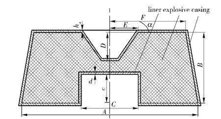
Fig.1 Charge structure
1.2 Geometrical Model
Based on Fig.1,the geometry model of the perforator and the finite-element model of perforator charge are shown in Fig.2 and Fig.3.
The model parameters are the liner diameterC=50 mm,depthc=25 mm,wall thicknessd=2 mm.charge diameterA=140 mm,heightB=66.5 mm,top widthF=66.5 mm,the depth of removal part in charge centerD=24.5 mm,aperture diameterE=25 mm,angleα=55°,shell thicknessha=2 mm.

Fig.2 Geometry model of perforator
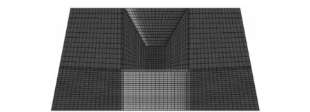
Fig.3 Finite element model
2 Numerical Simulations
2.1 Calculation Model
Trugrid software can be used to establish the calculation model and generate the finite element mesh.Because the structure is axial symmetric,the finite element model can only represent a quarter,as shown in Fig.3,to reduce the number of elements and save computation time.Euler multi-material algorithm can be used to simulate the cylindrical liner’s jet formation process.Lagrange’s grid can be used to modeling the shell and target,coupling arithmetic can be chosen to calculate the interaction among shell,target,liner and explosives,and the grid elements are solid 164 eightnode hexahedral elements.
2.2 Material Models and Parameters[7]
Octol is chosen as the explosives,the model*MAT_HIGH_EXPLOSIVE_BURN is used for it,and the Jones-Wilkins-Lee(JWL)equation of state(EOS)is used to calculate the pressure generated by the expansion of the detonation products of the chemical explosive.JWL EOS defines the pressure as

whereA,B,R1,R2andωare the material constants,pis the pressure,Vis the relative volume of detonation product,E0is the initial specific energy.The parameters of Octol used in this paper areρ=1.82 g/cm-3,D=8.48 km/s,PCJ=34.2 GPa,B=13.83 GPa,R1=4.5,R2=1.2,ω=0.38.
The liner is made of copper.MAT_JOHNSON_COOK material model and GRUNEISEN state equation can be used to describe the liner’s dynamic behavior in response to the detonation waves and simulate the material deformation problems under high strain conditions.The main parameters of liner material used in this paper areρ=8.96 g/cm3,G=50.9 GPa,PR=0.345,c=3.94 km/s,s1=1.49,A=0.47.
JOHNSON_HOLMQUIST_CONCRETE(HJC)constitutive equation and damage model are applied for the concrete targets.HJC model can well describe the response of concrete in high strain rate.The high pressure,high strain rate and damage effects are taken into account in its strength model.Damage accumulation includes the effects of plastic volumetric strain,equivalent plastic strain and pressure.The main parameters of the concrete target areρ=2.4 g/cm3,G=14.86 GPa,A=0.79,B=1.6,c=0.007,N=0.61,FC=0.048.
3 Simulation Results and Analyses
3.1 Jet Formation Process
For limited space,Fig.4 only illustrates the jet formation in the first 80 μs.We can see the liner collapsing, jetformation, jet stretch and breakup process.

Fig.4 Jet formation process
Fig.4 shows the jet density of cylindrical liner subjected to blast loading.Att=10 μs,the detonation wave arrives to the liner,and it begins to be collapsed.Att=15 μs,the jet moves and converges to the center of the liner aperture.Then,att=25 μs,the jet is formed.Att=40 μs andt=55 μs,the jet continues to be elongated.Att=80 μs,the jet diameter shrinkage and break occur.
It can also be known that the jet formation process of cylindrical liner is different from that of the common conical liner.When the detonation wave reaches to the liner’s surface,it collapses the liner’s top and side simultaneously,the liner’s material converges to the center of the liner aperture,and further forms a stable jet finally.Calculations show that most of materials on top form the tip of jet,while those in side form the tail of jet.
Fig.5 shows the velocity variation within 80 μs.It indicates the maximum velocity can be up to 12 450 m/s.Whent=80 μs,the velocity is over 2 000 m/s.
The simulation results also indicate that the liner thickness and shell status have big effect on the jet velocity,as shown in Tab.1 and Tab.2.

Fig.5 Variation of jet velocity
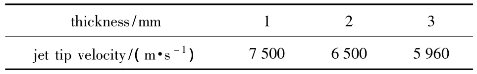
Tab.1 Jet velocity of liner with different ha
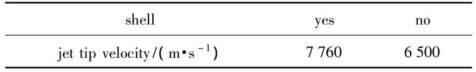
Tab.2 Jet velocity in different shell status
3.2 Failure Patten of Concrete Targets
Tab.3 shows the calculation results that the jet of cylindrical liner penetrates the concrete target of 25 mm in length and width and 275 mm in thickness.

Tab.3 Calculated target penetration
It can be seen that the cylindrical liner has a better jet continuity,and the ratio of cumulative jet length to liner diameter is 7.56.The ratio of bore diameter to liner diameter is from 0.36 to 1.The penetration depth is 5.5 times more than that of the liner diameter.
In Tab.3,Lis the cumulative jet length,Hmaxthe maximum hole diameter,Hminthe minimum hole diameter,v0the jet tip velocity after penetration,Vthe jet tail velocity after penetration,Tthe total time of penetration.
4 Conclusions
By using LS-DYNA finite element analysis software,this paper makes numerical simulations for jet formation and penetration processes in concrete targets.
The cylindrical liner can form cumulative jet under blast loading.The jet formation process is different from that of the single cone liner.When the detonation wave reaches to the surface of cylindrical liner,it collapses in top and side simultaneously,and then,the collapsed material converges at the center of the liner aperture,and further forms a stable jet.It can be seen from the calculations that the most materials on top form the jet,while those in side form the tail of jet.The jet of cylindrical liner has a better continuity.The ratio of bore diameter to liner diameter can be from 0.36 to 1.The penetration depth is 5.5 times more than that of the liner diameter.
[1]WANG Hai-dong,SUN Xin-bo.A summary of perforating technology development inside and outside of China[J].Explosive Materials,2006,35(3):33 -36.(in Chinese)
[2]SHI Hui-shen.Perforating-sandproof composite technology[J].Explosion and Shock Waves,2001,21(2):145-148.(in Chinese)
[3]LI Jin-qing.Research and discuss of new types oil perforator[J].Explosive Materials,2003,32(4):27 - 30.(in Chinese)
[4]ZHUANG Wei.Theoretical and experimental study on hydraulic sandblasting perforation[D].Dongying:China U-niversity of Petroleum,2006.(in Chinese)
[5]GUO Sheng-yan,XU Yong-sheng.On several factors influencing on the perforator depths of shaped charges[J].Well Logging Technology,2005,29(Suppl):52 -54.(in Chinese)
[6]GUO Sheng-yan,ZENG Xin-wu.Effect of bismuth on metal-powder-liner of petrol shaped-charge[J].Well Logging Technology,2002,26(4):338-340.(in Chinese)
[7]FAN Chen-yang,WANG Zhi-jun,WU Guo-dong.Numerical simulation on jet formation and projectile into concrete target of a new star shaped liner[J].Journal of Projectiles,Rockets,Missiles and Guidance,2010,30(3):99-102.(in Chinese)
[8]SHI Dang-yong,LI Yu-chun,ZHANG Sheng-min.Based on ANSYS/LS-DYNA explicit dynamic analysis[M].Beijing:Tsinghua University Press,2005.(in Chinese)
猜你喜欢
Chinese Physics B(2022年10期)2022-10-26
农业工程学报(2022年11期)2022-08-22
红蜻蜓·低年级(2021年8期)2021-08-23
早期教育(家庭教育)(2020年1期)2020-05-28
金秋(2019年14期)2019-10-23
速读·上旬(2019年4期)2019-09-10
南方文学(2015年3期)2015-07-15

- Defence Technology的其它文章
- Research on the Application of Explosive Network in the Shaped Charge Warhead
- Improvement of Intercept Probability Algorithm for Anti-ship Missile Based on Search Theory
- Research on the Fracture Mechanism of Scored Liner Under Explosive Loading
- Research on Complex Refraction Indices of Expanded Graphite
- Variable-mass Thermodynamics Calculation Model for Gas-operated Automatic Weapon
- Test and Analysis for Spraying Ammonia in Diesel Engine