Overcoming the Logistical Constraints of Ultra-LongUndersea Tunnels
2011-12-28 06:05GarethMainwaring
重庆交通大学学报(自然科学版) 2011年2期
Gareth Mainwaring
(Metros& Civil Engineering,Mott MacDondld,England)
1 Background
Rail is now being seen as a more sustainable solution to long-distance travel compared with air flights.More high-speed lines are being designed and built all around the world:throughout Europe,in China,Korea,Japan,Taiwan,and now in India.Further schemes are in the planning stages in North America,Brazil,South Africa,Australia and the Middle East.Although a world-wide network of high speed rail lines would currently appear to be impractical,there is still a desire to link each of the continental networks.The Channel Tunnel between UK and France has initiated that target for Europe,and the AlpTransit project which is currently under construction will further extend the network.It will be possible to travel throughout Europe by high-speed trains within the next few years.
The possibility of forming a similar system in North-East Asia,by connecting the rail lines in China,Taiwan,Korea and Japan is impeded by the geography of the region.The rail links would require the construction of a number of deep sea tunnels,all of which would be considerably longer than have ever been built to date.It is recognised that the construction of fixed links between Japan and Korea,China and Taiwan,and more recently between South Korea and China–thus avoiding North Korea,have long been the pipedreams of both engineers and politicians.Similarly the construction of a trans-Atlantic tunnel and a connection between North America and Russia are regularly featured on television programmes.A practical means of building ultra-along undersea tunnels remains a major challenge.
However,the solution for undertaking such major transportation projects may already exist:using the proven technology that has been used for the past 30 years in the oil and gas industry–the use of the gravity structures that have been constructed in areas such as the North Sea between UK and Scandinavia in Northern Europe.
2 Construction Logistics
Although the overall length of the Channel Tunnel is 50 km from portal to portal,the undersea portion is 38km in length.The tunnelling sites were located closer to the coastlines,and the longest of the tunnel drives was 22 km–which is that of the undersea portion extending from the UK coastline.The Seikan Tunnel is 53.8 km in total length,but only 23.3 km is undersea.Again the undersea portion was excavated from both shorelines,so the longest of the tunnel drives was of the order of 12 km.
The most recent ultra-long tunnel is not an undersea project,but the Gotthard Base Tunnel of the Alp-Transit Project which passes underneath a mountain range.The total length of this tunnel is 57 km,but with the use of intermediate shafts and access adits,the longest of the tunnel drives is 14km.Although it could have been possible to construct this project by minimising the number of tunnel drives,and the longest drives would have been comparable with those used for both the Channel Tunnel and Seikan Tunnels,it was considered that the most cost-effective way to construct the AlpTransit Project was to use multiple drives,via a number of shafts and adits the deepest of which was 800 m deep.
One of the major considerations with the construction logistics of tunnels is accessibility and the delivery of materials-and personnel-to the working face and the efficient removal of spoil.Above all is the provision of a safe working environment for the workforce.
The locomotives that are used to deliver tunnel segments and the workforce to the TBM are not highspeed trains,but generally operate at speeds of between 15-20 km/h.Indeed in the confines of a tunnel under construction it would be unsafe to operate locomotives at a speed which would be hazardous to the workers within the tunnel.Additionally,the faster the locomotive speed,then the greater the power they require,and if diesel powered,the greater the heat generated and the exhaust emissions created.Thus the ventilation ducts to the tunnel face increases in size.Overhead line power could be provided,but there are associated safety considerations with such a choice.
The temporary track installed for a construction locomotive is also not compatible with high speeds.For the Channel Tunnel,a high performance temporary track was installed which allowed the locomotives to travel at a maximum permissible speed of 30 km/h.However,towards the end of the tunnel drives,when the length of the tunnel exceeded 20 km,then it took the workforce almost an hour to reach the TBM,and a similar duration at the end of the shift to exit the tunnel.Labour costs quickly become a major factor when 20%of each working day is spent travelling to the tunnel face.Ultra-long tunnels would encounter even greater travel times,and it is considered that these considerations would have been a major factor in the construction of the intermediate shafts and adits for the Gotthard Base Tunnel.
The examples described above,together with another major undersea tunnel,Storebaelt Railway Project in Denmark,all are based on the premise that the TBM drives are converging.Thus in the event that a major breakdown is experienced with one of the tunnelling machines then the other TBM can continue for a further distance than originally planned.A major TBM breakdown in an ultra-long undersea tunnel,when it is impossible to form an intervention shaft,and the opposite TBM has a an excessive distance to tunnel would compound all the logistical issues mentioned above,plus would probably exceed the capabilities of the TBM itself,necessitating a number of major overhauls which would impact on the construction programme.
Again,the use of multiple tunnel drives for the Gotthard Base Tunnel would seem to be a logical decision.The issue for consideration would be how to provide the intermediate staging point for an ultra-long tunnel that is located in the deep sea?
3 Operational Requirements
3.1 Temperature
Electrical power used by locomotives in overcoming aerodynamics and rolling resistances degrades into heat.Within a tunnel environment,this is supplemented by heat from power losses,train air conditioning systems and tunnel services.The average level of heat generated in the Channel Tunnel has been calculated at 80MW,with only 10MW conducted away through rock strata and tunnel ventilation.
A cooling system is therefore needed to maintain air temperatures below 25°C.Without cooling,air temperatures could reach 50°C after 2 to 3 months – and this is in the temperate climate of Northern Europe.The cooling of the tunnel is provided by water chilled to 3℃which is circulated through 400 mm pipes mounted on the walls of the running tunnels.Longer tunnels would require larger pipes,as the water temperature could not be lowered any further.
3.2 Air Quality
Maintaining air quality during the operations of the tunnel is a fundamental design issue for the safety of the users of the system.Generally fresh air is pushed through the running tunnels by the movement of trains.However,if a central services tunnel is required,then other means of ventilation is needed.For the Channel Tunnel there are two ventilation systems within the tunnels:the normal ventilation system(NVS),and the supplementary ventilation system(SVS),which is used during emergency conditions.
The NVS provides fresh air to the service tunnel from fans located at each of the shorelines.The capacity of these fans and the provision of air-control devices in the cross-passages ensure that the air in the service tunnel is separated from the running tunnels and is kept pressurised at all times.
The emergency SVS provides smoke control and purging of the running tunnels in the event of a fire.Again,the fans are located on each of the shorelines.The SVS fans for the Channel Tunnel supply 300 m3/s of air directly into the running tunnels,sufficient to induce longitudinal airflows around stationary trains.
Obviously larger or additional fans could be provided to supply the necessary ventilation systems for longer tunnels.However,the relationship between tunnel length and fan capacity is not linear,and the complexity of the ventilation design increases with the length of the tunnel as there are likely to be more trains within the tunnel.The provision of intermediate ventilation installations would greatly benefit the efficiency of the air quality systems.However,this is not practical with undersea tunnels unless an intermediate connection to surface can be provided.
3.3 Drainage
To reduce hydrostatic loads on the tunnel linings,small groundwater flows are permitted through the joints of the segmental concrete linings used for the Channel Tunnel.The seepage water is collected in a carrier drain located in the invert of each of the tunnels,and is collected in two pump stations located 5 km and 15 km from the shorelines.
The collected seepage water is then pumped back to the mainland via four pipes,each 400 mm in diameter which are located in the service tunnel.The space provisions for these pipes has a significant impact on the diameter of the service tunnel.
3.4 Fire & Life Safety
One of the major considerations in the design of a transportation tunnel is the provision of a place of safety in the event of a major incident such as a fire occurring in the tunnel.This is usually accommodated by the provision of cross passages or escape routes to allow passengers to vacate the incident tunnel.Any new tunnel would be designed in full accordance with international safety requirements irrespective of length of tunnel.However,for an ultra-long tunnel,a major issue comes with access for emergency services and evacuation of injured people if incident occurred a long way from the shoreline.The international standards do not give precise guidelines on the time required for the emergency services to reach the scene of the incident,or to attend to casualties.For facilities such as the Channel Tunnel,a dedicated response crew is employed so that any incident can be responded to immediately.However,the incident could still occur 25 km away from where the response crew is based,and the time for them to reach the scene would be longer than for an accident occurring in an urban environment.For an ultra-long tunnel,the time could be considerably longer and potentially unacceptable in terms of safety.
3.5 Conclusion
It is considered that any ultra-long transportation tunnel which will accommodate people would benefit by the inclusion of intermediate access point along the route.This has been provided for the AlpTransit project,but would seem to be impractical for undersea tunnels unless islands are formed along the align-ment.However,for most undersea tunnels the sea depth would generally be in excess of 100 metres,which would make the formation of man-made islands impossible.Other options should therefore be investigated.
4 Off-Shore Gravity Structures
One method of providing intermediate“islands”along the length of a major undersea tunnel,which would not only be of benefit for the construction logistics but would also provide a means of compartmentalising the overall tunnel into manageable section,would be to use the proven technology gained from the oil industry(Fig.1).
It is possible to locate a number of major concrete gravity structures along the alignment.These gravity structures have been successfully used for over 30 years for oil and gas production mainly in the Norwegian sector of the North Sea.Installation depths of over 300 m greatly exceed those to be encountered on any tunnel route between say Japan and Korea,or between China and Taiwan.
The Draugen platform in the Norwegian sector of the North Sea is the model for the structures intended for use in the ultra-long undersea tunnel.It has a central shaft of 20 m diameter and accommodation modules for the workforce are secured on the topsides superstructure.The design of the operational support systems on the“topsides”is greatly simplified and rendered safer by the absence of the pressurised hydrocarbons and associated process plant that is required for the oil and gas industry.The structures would instead be used as construction sites for the proposed tunnel,with tunnelling being carried out in two directions from each structure.
The space available on the“topside”is more than adequate for accommodating the personnel required for manning the multiple TBMs that would undertake the tunnelling works and for the generators and workshops required to support the tunnelling operations.Tunnel segments would be delivered by barges which could be moored alongside the platform.
For the permanent works,the structures would provide the means of ventilating the ultra-long tunnel,the discharging of drainage water,and would also provide emergency access/egress points along the route.It is the novel use of this proven technology which can provide the means of overcoming the logistical constraints of both constructing and operating an ultra long undersea tunnel.
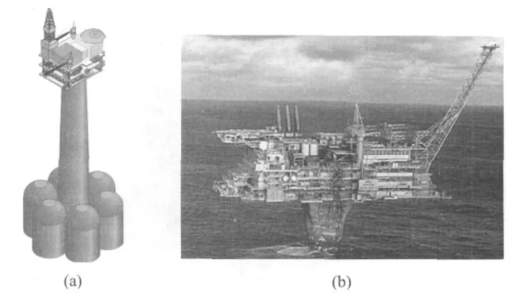
Fig.1 Gravity structures used in the off-shore oil& gas industry图1 海岸石油和天然气重力结构
5 Construction Methodology
If it were to be assumed that the configuration of a major undersea tunnel would be similar to that of the Channel Tunnel,i.e.2 × running tunnels plus a central service tunnel,then each of the intermediate construction shafts would need to service the construction of six tunnel faces concurrently-again assuming that tunnelling would need to progress in two directions from each shaft.The most practical way this could be undertaken would be via a large cavern formed below the sea bed at each of the shaft locations.
One of the main considerations in the feasibility of the proposed construction method is the means of securing the gravity structure into the seabed,and the logistics for different ground conditions are assessed in greater detail as follows.At each location selected as a site for a concrete structure,the seabed would need to be surveyed in order to establish which method would be used for the installation of the base.
The use of caissons to penetrate the upper soils and provide a solid connection into the underlying rock is again proven technology(Fig.2).The caisson would have internal dimensions which would permit subsequent passage of drilling and tunnelling equipment,and a wall thickness which would resist all loads encountered during installation and operation.Pipework through which jetting mud and fixing/sealing grouts can pass would be incorporated into the walls of the caisson,with the fluids being pumped from surface vessels typically through flexible piping attached to the top of the caisson.

Fig.2 Use of caissons for penetrating overlying soft ground图2 穿过软土层沉箱示意
At the bottom of the caisson would be a cutting profile,preferably of steel,as typically employed in the civil engineering sector.The caisson can penetrate the soil by a combination of self-weight,jetting,and by excavation of soil inside the caisson as required to reduce wall friction.In the event that these measures are insufficient to set the caisson at required depth,piledriving equipment attached to the caisson through an appropriate interface-the tieback liner to be subsequently installed is such an interface-would ensure final attainment of setting depth.
Upon reaching the bedrock,under-reaming drilling would be used to remove rock immediately below the caisson to allow penetration to a required depth.The drilling equipment would be mounted onto an integral circumferential rail sited on the bore of the caisson and would be powered by drilling mud:cuttings would be removed by a suction system as part of the drilling equipment.The weight of the caisson can be suspended and controlled during drilling operations.After attaining the requisite depth,the caisson is cemented into place with sufficient volume of concrete to ensure that the bore of the caisson is sealed.In order to direct the slurry towards the outside of the caisson,a weighted cover would be landed on the caisson just prior to pumping of concrete.On completion of cementing and after waiting on concrete to harden,its integrity can be tested by pressuring the inside of the caisson through the weight cap.
The gravity structure would then be towed over the caisson and landed on the surrounding soil.After landing the structure,successive caisson elements would be landed through the shaft of the structure and cemented to each other until the stacked elements comprise a liner reaching the surface of the structure.The water within the caisson shaft can now be pumped out and shaft sinking operations inside and below the liner may commence.This configuration is necessary to ensure that no loading is transferred to the sealing caisson from the structure set on the soil.It should also be noted that,in the absence of a seal between the structure and liner,there is a hydrostatic pressure in the annulus between the structure and the liner.The completed system is shown in Fig.3.

Fig.3 Completed shaft and cavern图3 成孔情况示意
Where the seabed is of rock or with light removable topsoil cover,a different method must be employed as preparation for the landing of the gravity structure.On the area of seabed where the base would be landed,a pattern of fixing posts would need to be drilled and cemented.If necessary,the surface on the target seabed could be modified by excavation.The base would be landed in the target and the posts would pass through columnar elements in the base.Concrete would then be pumped through the base via integrated pipes to expel all seawater underneath the base and also to cement the base to the posts.After the concrete has set,the gravity structure can be landed on the base.The interface area between the extended column of the base and the structure shall then be cemented via piping integral to the structure.The water column inside the shaft of the structure can be pumped out after this concrete sets:all paths for ingress of seawater into the central shaft have been sealed by concrete.
After completion of pumping operations for either of the methods of landing preparation,a shaft would be formed through the ground rock and would be of a diameter of sufficient size to allow passage of elements of tunnel-boring machines(TBMs)which would be assembled in a cavern.The cavern would provide an assembly workshop for the TBMs,and the muck from each face would be conveyed up the shaft to the topsides unit for loading onto ships which would transport the muck to disposal sites.The cavern can serve as a crossover when the tunnel is completed,which is of benefit to subsequent rail operations.
The methods and procedures stated would be repeated at each location of concrete structure.
6 Major Benefits
The benefits of intermediate staging points for tunnel construction are numerous.Not only can work be carried out more quickly,by undertaking a number of faces simultaneously,but the overall flexibility of the construction programme is enhanced.Should one TBM suffer a major breakdown then the opposite TBM would still be working and the meeting point would be adjusted accordingly.The overall construction schedule is also shortened considerably with multiple drives.
It would be expected that during the construction of a long tunnel that a variety of ground conditions would be encountered.If such a tunnel were to be constructed from a single face,then the TBM would need to be designed to cope with all the different types of ground conditions.The efficiency of the TBM and production rates would be likely to suffer as the“one size fits all”machine is not specifically tailored to the conditions at a particular location.By dividing the overall tunnel into a number of smaller sections,it may be possible to build the tunnel with TBMs that are specifically designed to the ground conditions along that section.
The operation of the completed facility would also see benefits as the shafts would be utilised as permanent ventilation points along the length of the tunnel,and would also serve as emergency escape routes in the event of an incident.The location of wind turbines and solar panels on each of the gravity structures could also provide an energy efficient means of providing power for the ventilation fans and the other services required to operate the facility.This could also reduce the number of sub-stations that would normally be required to be installed within the tunnel itself.
7 Potential Applications
A number of routes have been identified where fixed links are desired.A link between Japan and Korea has been the subject of a number of studies extending many years.The shortest route for this link would require an undersea tunnel of 128 km in length,but with a maximum water depth of 220 m for this particular route.Shallower water depths can be identified,but the associated tunnel lengths are greater.
More recently a tunnel linking South Korea and China has been discussed,the route of which across the Yellow Sea from near Incheon in Korea to Shandong region in China would require a tunnel in excess of 300 km to be formed under the sea.It is noted that there are no islands in the Yellow Sea to simplify the construction logistics.However,the use of gravity structures would be an obvious solution.
A tunnel across the Taiwan Straits to link mainland China with Taiwan would be approximately 150 km in length.The depth of the sea is approximately 70 m,which is well within the range of the gravity structures described in this paper.The use of 4 gravity structures to form intermediate staging points along the route would allow the tunnel to be divided into 5 sections,each 30 km in length.The longest tunnel drive would then be 15 km,which is similar to the longest drive on the Gotthard Base Tunnel.It is acknowledged that any platform located in the Taiwan Straits would need to be designed to resist major seismic loadings and the adverse weather conditions encountered during typhoons.However,the fact that these types of structures have been built in the harsh environment of the North Sea,and are still operational after 30 years demonstrates that these challenges can be met.
8 Conclusions
It is recognised that more transportation links are being constructed all around the world,and that high speed rail lines are being considered as a more sustainable option than air travel.The next stage of the evolution of the fixed links would be the construction of major undersea tunnels that would eclipse the Channel Tunnel in terms of length and complexity.
It can be demonstrated that a viable method for constructing these ultra-long undersea tunnels already exists,and the method proposed has major benefits for both the construction logistics and the long-term operations of the rail link.
The use of technology developed by the Oil&Gas industry would seem to have major benefits in providing sustainable solutions to some of the world’s transport requirements.
[1]Sharp A,Mainwaring G D.Method for the Accelerated Construction of Ultra-Long Subsea Tunnels(Japan-Korea/China-Taiwan)[C].Seoul,Korea:3rd CECAR Conference,2004.
[2]Southwood A J.The Channel Tunnel,A Designer’s Perspective[M].Croydon:Mott MacDondld International Ltd.,1994.
[3]Hee Soon Shin.Use of Underground Space in Korea[M].Korea:Tunnels & Tunnelling International,2011.
猜你喜欢
科学大众(2022年23期)2023-01-30
珠江水运(2022年9期)2022-06-09
建设监理(2021年10期)2021-12-30
建材发展导向(2021年20期)2021-11-20
建材发展导向(2021年10期)2021-07-16
建材发展导向(2021年6期)2021-06-09
中华养生保健(2020年10期)2021-01-18
珠江水运(2020年9期)2020-06-03
江西建材(2018年4期)2018-04-10
中华建设(2017年1期)2017-06-07