
Response mechanism for widened pavement structure subjected to ground differential settlement
2013-09-17 06:00WengXiaolinCuiZhifangSongWenjiaMaHaohao
Weng Xiaolin Cui Zhifang Song Wenjia Ma Haohao
(1Key Laboratory for Special Area Highway Engineering of Ministry of Education,Chang'an University,Xi'an 710064,China)
(2He'nan Zhongyuan Expressway Co., Ltd., Zhengzhou 450052, China)
I n a widened road,the newly-added subgrade will generate a secondary stress field in the original subgrade and the natural ground(or foundation)in which consolidation deformation has completed and eventually caused additional settlement[1].Differential settlement can cause additional stress in the spliced pavement structure leading eventually to structural failure.Therefore, it is necessary to develop in-depth researches regarding the stress/strain response mechanism of the widened pavement structure.By now,a number of research programs have been developed on this subject at home and abroad and fruitful results have been achieved.For example, Tan et al.[2]put forward a calculation method for the analysis of additional stress in the pavement structure as caused by the differential settlement of the soft foundation.Huang and his team[3], by doing finite element simulation and model tests,verified that failures of widened highways are directly related to the differential settlement between the new and the old subgrades.Refs.[4-6]introduced the calculation and analysis of the additional stress in pavement as caused by ground differential settlement and Ref.[7]recommended the allowable limit of transverse differential settlement using the finite element calculation.It should be pointed out that problems are found, however,with all these research programs such as unsystematic test results and lack of observation data of the prototype.As for the conventional model test,due to the size limit of the model box,it cannot truly represent the prototype as far as the mechanical properties are concerned.As the result, these research programs, unfortunately, are unable to provide necessary data support for the study of the response mechanism of pavement under the influence of ground differential settlement.Meanwhile, because of the lack of understanding,both the differential settlement and its influencing elements,the theoretical support of controlling a standard establishment still remains unavailable.Based on previous research programs,this paper presents a full-size model test performed by the use of a largescale ground differential settlement simulator to measure the strain response of both the cement-stabilized gravel base course and the typical asphalt pavement.Further analysis is made to determine the law of deformation and the strain characteristics of the pavement structure in response to ground differential settlement,and to establish a model for the hollow areas beneath the bottom of different pavement structures.At the same time, this paper also introduces the finite element analysis based on the model test results in an effort to obtain the failure stress of the wearing course and to determine the critical control standards for differential settlement at the bottom of the pavement structure.This paper is expected to provide a helpful reference for the design and construction of high-way widening projects.
1 Model Test for Widened Pavement Structure Subjected to Differential Settlement
1.1 Ground settlement system
For a widened road,the settlement of a newly placed subgrade will arrive at a relative fast rate shortly after the placement and then gradually slow down.Considering the time for pavement construction,it can be assumed that the consolidation settlement of the new subgrade is substantially completed shortly after the road opening to traffic[8].Therefore, the differential settlement of the subgrade, on that premise, is mainly caused by that of the natural ground(foundation).The large scale ground differential settlement simulator, as shown in Fig.1, is mainly composed of the jacking system,the supporting system and the monitoring system.It can simulate differential settlement with various magnitudes between 0 to 25 cm.The jacking system employs a large amount of 100 t self-lock jacks together with a number of industrial computers and sensors;the monitoring system is made up of monitoring elements and a data acquisition system(DAS);and the supporting system mainly contains a platform,which is composed of a number of panels that can make moving and rotating motion,thus provides a“ground surface”of a certain dynamic effect.

Fig.1 Ground differential settlement simulator.(a)Support system;(b)Settlement system
According to Ref.[9], assuming that the minimum settlementS1occurs on the centre line of the original road and the maximum settlementS2on the shoulder of the new subgrade,andS2-S1is the differential settlement between the new and the original subgrades,represented byS.By adjusting the lift of the jacks at different locations,Scan be preset between 2 and 22 cm against which the response of subgrade soil and reinforcing materials are to be measured.
1.2 Test model
The test model is a stretch of road of half-width as shown in Fig.2.It has a top width of 6 m and a bottom width of 10.5 m, which is respectively increased up to 10 m and 14.5 m after subgrade widening.The subgrade soil is taken from an expressway site in the suburb of Xi'an City.The compaction test is performed according to “Test methods of soils for highway engineering”(JTG E40—2007)and an optimum water content of 13.2%is obtained.Lime soil(with a caustic lime content of 6%)is applied for the old subgrade to simulate the stiffness difference with the new one.To ensure the sound splicing between the new and the old subgrades,steps sizing 50 cm ×75 cm are cut on the surface of the latter.The new subgrade fill is to be placed when the old subgrade goes to a height of 2.2 m.In consideration of the border condition,a concrete wall is cast along the centre line of the old subgrade against which the embankment fill is placed.
The pavement is constructed the same way as that of a real road.It contains a 3-layered base course of cementstabilized gravel(18 cm in thickness for each),and a 3-layered wearing course of asphalt cement which includes a 4 cm upper layer(i.e.surface course)of AC-13, a 6 cm middle layer and a 10 cm bottom layer of AC-25.The compaction tests are performed on the cement-stabilized gravel that is mixed at various water contents of 4%,5%,6%,7%and 8%,upon which a maximum dry density ρmax=2.32 g/cm3and a maximum water contentwopt=5.5%are obtained.Test specimens are prepared by the static compaction method for the unconfined compressive strength tests.After being released, the specimens are sealed for indoor curing at an ambient temperature of(20±2)℃ for 6 d, and then soaked in water for 1 d.The average unconfined compressive strength of the specimens after 7 d of curing is 4.21 MPa, which surpasses 4 MPa and meets the specification requirements.The cement-stabilized gravel is manually mixed, spread, and compacted with a 12 t roller.The test on the core samples of the asphalt pavement confirms a compactness greater than 95%that meets the requirement of the construction specifications.
1.3 Pavement structure and monitoring system
The cement-stabilized gravel base course has three layers, 18 cm in thickness each, with cement contents of 4%,5%,and 6%from bottom to top,respectively.20 concrete strain gauges are embedded in the subbase,which are denoted as YB-1 to YB-4 in the geogrid-reinforced area and YB-5 to YB-8 in the non-geogrid-reinforced area.For the upper layer and the middle layer, six concrete strain gauges are embedded in each which are,respectively,denoted as YB-9 to YB-11 and YB-15 to YB-17 in the geogrid-reinforced area and YB-12 to YB-14 and YB-18 to YB-20 in the non-geogrid-reinforced area, as shown in Fig.3.A monitoring section is placed transversely across each layer of the wearing course.Each section contains five fiber Bragg grating(FBG)strain sensors, numbering FGB1 to FGB5, that are connected in series to monitor the strain in lateral and longitudinal directions.Signals are transmitted through the optical fiber to a channel expander and the Bragg grating demodulator for data collection.

Fig.2 The detail of widened pavement structure(unit:cm)
1.4 Strain analysis for cement-stabilized base course
Fig.4 shows the relationship between the additional strain in the cement-stabilized base course and the differential settlement of foundation.It indicates that sensors YB-4,YB-6, and YB-10 record the strains of peak value,suggesting that the maximum additional stress as caused by the differential ground settlement occurred near the splicing joint.It is found that the bottom layer bears the greatest strain;in other words,this area is most influenced by the differential settlement of foundation.It is observed from Fig.4 that the strain in all the three layers is maintained at a low level in the case of a small magnitude ofSand gradually goes up with an increase inSuntil the peak value occurs in YB-3 and YB-4 whenSreaches 14 cm,and then the curve tends to be steady with a further increase inS.Gauges YB-4, YB-11 and YB-17 respectively record the maximum strain of each layer,which suggests that the location in which the maximum strain resides is not the splicing joint,but at an area about 1 m away from it.Gauges YB-1, YB9, and YB15, due to their proximity to the centre line of the original subgrade, only record strains of relative small value.In response to the increasingS,the stress in this area gradually changes from compressive to tensile,which well reflects the deformation compatibility of the base course.It is also found that the transverse strain of Fig.4(a)is relatively lower than that of Fig.4(b)due to the application of the geogrid.
1.5 Strain analysis for asphalt cement wearing course
Fig.5 illustrates the relationship between the strain in the asphalt cement wearing course and the differential settlement of the foundation.It can be seen that the wearing course is subjected to the tensile stress with the differential settlement being imposed.The stress gradually goes up with the increase inSand shows a relative steady tendency and small magnitude beforeSreaches 14 cm.This in-dicates that the differential settlement of a minor magnitude, relieved by the subgrade and the base course, cannot cause obvious strain in the wearing course.WhenSis greater than 14 cm,however,the strain begins to increase far more rapidly and causes plastic deformation in the pavement.Comparisons are made among the three layers of the wearing course to find that the bottom layer experiences the biggest strain with a maximum of 2.112 ×10⁻³, next is the middle layer of 1.687 × 10⁻³, and the upper layer of 1.547 ×10⁻³.
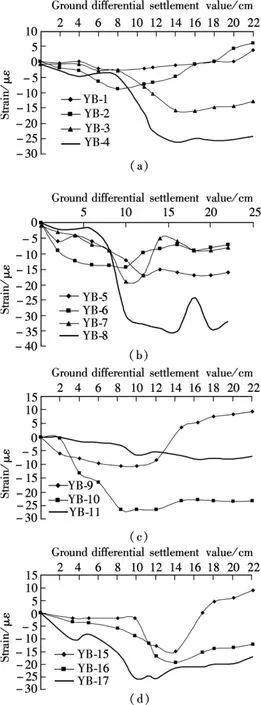
Fig.4 Relationships between strain in base course and ground differential settlement.(a)Bottom layer of base course(reinforced by geogrid);(b)Bottom layer of base course(non-reinforced by geogrid);(c)Middle layer of base course;(d)Upper layer of base course(subbase)
1.6 Analysis of settlement of pavement layers

Fig.5 Relationships between strain in wearing course and ground differential settlement.(a)Upper layer of wearing course(surface course);(b)Middle layer of wearing course;(c)Bottom layer of wearing course
As shown in Fig.6, the settlement of the surface course increases gradually with the growth of the ground differential settlement and reaches a peak value around the gravity centre of the new subgrade.Although plastic deformation occurs in the pavement structure when the ground differential settlement valueSreaches 14 cm,according to Fig.6,the differential settlement of the surface course at this point is merely 1.08 cm;even whenSgoes up further to 22 cm,the latter only increases slightly up to 1.54 cm.This suggests the existence of hollows(or gaps)between the new subgrade surface and the bottom of the pavement.For a widened road, especially those constructed on a soft foundation,there are several elements involved in the formation of these hollows,which mainly include differential settlements caused by compression and consolidation of the ground,the unevenness of the accumulative plastic deformation of the ground,and the compressive deformation of the new subgrade.

Fig.6 Variation tendency of surface course settlement
2 Analysis ofAdditionalStressofWidened Pavement Structure
2.1 Finite element model of pavement structure
The model road contains a stretch of old subgrade which is 20 m in length and 12 m in width and is widened symmetrically by 4 m on each side.It is given in half width for finite element analysis in consideration of structural symmetry.The dead load of the pavement structure is taken into account while the traffic load is omitted for finite element calculation of which major parameters are given in Tab.1.
The boundary conditions for finite element analysis includes a left margin with constraint on the horizontal displacement,together with a free upper margin and a right margin.To simply calculate an uneven displacement,constraint is directly imposed on the bottom of the pavement on the assumption that differential settlement has already occurred in this area.The flexural tensile stress of different pavement layers is calculated at varying degrees of δmaxbetween 1 and 10 cm.
2.2 Influence of differential settlement on additional stress
The cross section of 1 m from the splicing joint is selected for analysis.Tab.2 shows the additional stress obtained through calculation for the surfaces of the wearing course, the base course, and the subbase, respectively.It can be learnt that the tensile stress is applied in the surface of the wearing course that varies in an approximate linear relation with the differential settlement;the surface of the base course is also subjected to the tensile stress,which increases from 0.276 to 2.75 MPa when the differential settlement at the bottom of pavement δmaxvaries in steps from 1 to 10 cm.Compared with the allowable tensile stress of 0.28 MPa for the base course, which is specified in“Specifications for design of highway asphalt pavement”, it can be concluded that when δmaxexceeds 1 cm,the horizontal additional stress in the base course will surpass the allowable tensile stress and cause fatigue cracking.This validates the results of the full-size model test.

Tab.1 Calculation parameters for finite element model
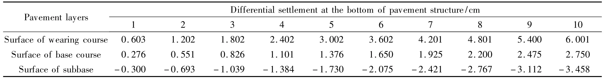
Tab.2 Horizontal additional stress in pavement layers corresponding to varying degree of differential settlement MPa
3 Conclusions
1)Compressive stress is applied in the base course and tensile stress in the wearing course of the pavement under the action of the ground differential settlement.Plastic deformation will develop in the pavement when the value of the ground differential settlementSreaches 14 cm.
2)When the differential settlement at the bottom of the pavement goes up to 1 cm,a maximum tensile strength as much as 0.28 MPa is obtained in the surface of the base course, which surpasses 0.276 MPa that is specified in the current specifications as the maximum splitting tensile strength for cement-stabilized base materials.
[1]Ma Xiaohui.Research on mechanic response of jointed pavement structure in highway widening project[D].Shanghai:School of Transportation Engineering,Tongji University,2008.(in Chinese)
[2]Tan Zhiming, Yao Zukang.Structural analysis of concrete pavements on soft subsoils with differential settlements[J].The Journal of Geotechnical Engineering, 1989,11(2):54-63.(in Chinese)
[3]Huang Qinlong, Lin Jianming, Qian Jinsong.Influence of pavement under discrepant deformation after construction between existing subgrade and that to be widened [J].Journal of Tongji University:Natural Science, 2005, 33(1):759-762.(in Chinese)
[4]Allersma H G B,Ravenswaay L,Vos E.Investigation of road widening on soft soil using a small centrifuge [J].Transportation Research Record, 1994,1462:47-53.
[5]Han J, Akins K.Use of geogrid-reinforced and pile-supported earth structures[C]//Proceedings of International Deep Foundation Congress.Orlando, FL, USA, 2002:668-679.
[6]Habib H A A, Brugman M H A, Uijlting B G J.Widening of Road N247 founded on a geogrid reinforced mattress on piles[C]//Proceedings of the Seventh International Conference on Geosynthetics.Nice, France, 2002:369-372.
[7]Fu Zhen, Wang Xuancang, Chen Xingguang, et al.Differential settlement characteristics and influencing factors of widening subgrade[J].Journal of Traffic and Transportation Engineering, 2007, 7(1):54-55.(in Chinese)
[8]Weng Xiaolin, Wang Wei, Liu Baojian.Model experimental research on deformation characteristics of widening loess roadbed and dynamic compaction method effect[J].China Journal of Highway and Transport,2011, 24(2):17-22.(in Chinese)
[9]Weng Xiaolin, Zhang Liujun, Li Lintao, et al.Model test on control techniques for differential settlement of roading widening[J].Chinese Journal of Geotechnical Engineering,2011,33(1):159-164.(in Chinese)
 Journal of Southeast University(English Edition)2013年1期
- Journal of Southeast University(English Edition)的其它文章
- A personalized trustworthy service selection method
- L1-norm minimization for quaternion signals
- Feature combination via importance-inhibition analysis
- W-band sharp-rejection bandpass filter with notch cavities
- Factors affecting headway regularity on bus routes
- Optimization of RDF link traversal based query execution