
Control strategy for hybrid tracked vehicles using fuzzy logic
2013-11-05 07:30CHENZeyu陈泽宇ZHAOGuangyao赵广耀ZHANGChengning张承宁ZHAILi翟丽
CHEN Ze-yu(陈泽宇), ZHAO Guang-yao(赵广耀),ZHANG Cheng-ning(张承宁), ZHAI Li(翟丽)
(1.School of Mechanical Engineering and Automation,Northeastern University,Shenyang 110819,China;2.School of Mechanical Engineering,Beijing Institute of Technology,Beijing 100081,China)
Hybrid tracked vehicles(HTV)use hybrid electric drive system to propel the tracks.The most tangible benefit of hybrid electric drive is the available onboard electric power source[1-3]that consists of two electric power units,the enginegenerator(EG)group and the battery.Electric power source can supply continuous power to meet requirements such as propulsion and intermittent power to accelerate or climb.The battery onboard can also be used to meet silent watch and silent mobility requirements.Second benefit of hybrid electric drive is the improved fuel economy by about 25%-30%according to the research by the US HMMWV programme[4].
Many power units in HTV need to work together so it’s necessary to design a control strategy[5~9]to meet the electric power demand and coordinate the power units.In this paper,a control strategy based on two fuzzy logics is proposed.
1 Power system integration
Power system integration structure of HTV is shown in Fig.1.Vehicles are driven by electric motors.Capacitor can supply for the electromagnetic armor.Motors and capacitor’s power are supplied by EG group or battery bank.EG group is utilized as a primary energy source to meet average power.Battery can work with EG group to meet peak power requirement.Both battery and capacitor can be utilized in silent mode and regeneration braking.
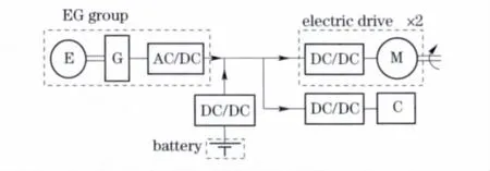
Fig.1 Power system integration structure
Control system assigns motors’power requirement to the EG group and battery bank based on power distribution algorithms.The overall control strategy is shown in Fig.2.From the information of EG group,power demand target voltage of DC bus Udand the reference rotate speed of engine can be deduced.Engine ECU get the information of power command from supervisory control strategy and then get through two PI loop shown as
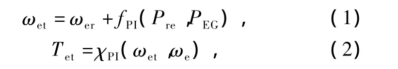
where ωetis the rotate speed target of engine,ωeris the rotate speed reference by table look-up,PEGis the power of EG group,Preis power requirement value of EG group,Tetis target torque value of engine,ωeis the actual engine rotate speed.
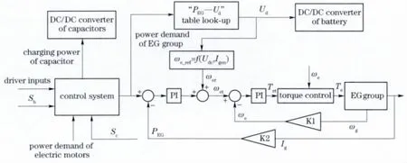
Fig.2 Supervisory control strategy
The equivalent circuit of generator plus a rectifier[10]is shown in Fig.3.The generator current can be calculated as

where Igis the generator current to DC bus,Kxand Keare system coefficients,ωgis the rotate speed of generator.

Fig.3 Equivalent circuit of generator plus rectifier
Engine and generator have a coupling relationship.The input torque of the generator is the load of engine,which can be modeled as

where ηegis the efficiency of transmission from engine to generator,Tgis the input torque of generator,iegis the transmission ratio from engine to generator,and Jegand Jgare rotational inertia of engine and generator.
2 Electric loads onboard analysis
Take a 35 t vehicle as research object,a 920 kW engine,550 kW electric motor,35 MJ battery and 4 MJ capacitor are used to meet power requirement.Electric power used for appurtenances such as lamps is much less than for vehicle traction,so it can be ignored here.Power loads supplied by electric energy onboard can be described as

where Preis the total power requirement onboard,Pmis the electric motors power requirement,Pcis target power for charging the capacitor,γcis the parameter reflecting capacitors SOC Sc.
Motors’power requirement from DC-bus is determined by the driveracceleration pedal,which can be calculated as
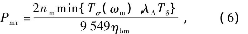
where nmis the motor rotate speed,Tσ(ωm)is the maximum value of motor torque at current rotate speed,Tδis the peak torque of motor,ηbmis efficiency from DC-bus to motors.λAis the accel-eration input signal of driver,defined as
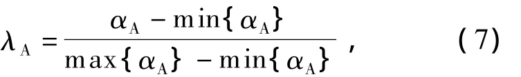
where αAis the angle of acceleration pedal.
3 Power distribution algorithm
Flowchartofpowermanagementcontrol strategy is shown in Fig.4.Target of the control strategy is to meet highly dynamic property while maintaining the system efficiency as possible.When power loads PLexceed the peak power of EG group Pa,EG provides the most part of power requirement by working at Pawhile the battery are supplement.When power loads are less than power of the minimum of EG group advantageous range Pi,battery supply the power units and engine shut off.If power requirement is beyond the maximum limit of battery power Pb,capacitors works for assistant.But if battery SOC Sbis below 0.4,engine works on and charges the battery while supplying the power requirement.
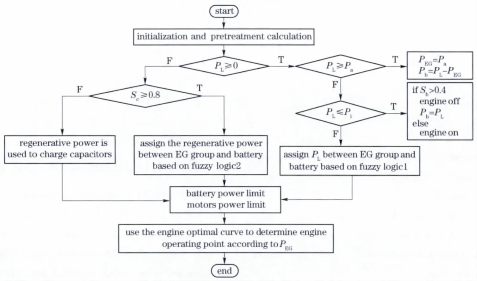
Fig.4 Power distribution strategy flowchart
If power loads are between peak power and minimum limit of EG group,EG group supply the whole power requirement and charge the battery.A Mamdani fuzzy algorithm with two input and one output ports is utilized to manage the powerflow at this situation.Two fuzzy inputs are Sband the ratio of the remaining power of EG group after undertaking loads λP,calculated as

Fuzzy output value is a coefficient ζFreflecting the ratio of power charging for battery to EG group remaining power,expressed as

Fuzzy memberships of λP, Sband ζFare shown in Fig.5.Target of fuzzy algorithm is to determine the engine power output based on Sband λP.According to memberships,fuzzy rules are established as expressed in Tab.1.
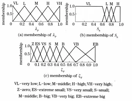
Fig.5 Membership functions of fuzzy variables

Tab.1 Fuzzy control rules
Fuzzy muster uses Zadeh arithmetic,which is defined as

Towards fuzzy input λP=A*and Sb=B*,some rules will be excited and calculate by Zadeh arithmetic.The total fuzzy implication is obtained by
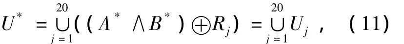
where Ujis the fuzzy output by rule j,U*is the total output,A*and B*are fuzzy membership.
When vehicle braking regenerative energy is first absorbed by capacitor before used to charge battery.Engine keeps open during braking because the tracked vehicle braking process is usually transitory and high dynamics property is required.
Here the power of EG group set is decided using a Sugeno fuzzy algorithm according to Sband regenerative power Pbr,shown as

where ψ (Sb,Pbr)is coefficient decided by fuzzy algorithm and ηiis the inverter efficiency.Normalization pretreatment of Pbris expressed by

where Pbcis the battery charging power.The fuzzy input Sband μrmembership are shown in Fig.6.
On the basis of membership of Sband μrseven fuzzy control rules are established,the fuzzy control strategy is to utilize EG group together with the regeneration power to charge the battery when Sbis low and regenerative power is small.Some of rules are shown as follows:
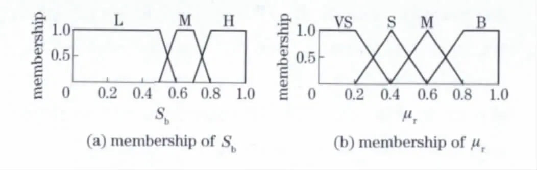
Fig.6 Membership of Sband μr
① if Sb=L and μr=S then ψ =0.7;
② if Sb=M and μr=M then ψ =0.25;
③ if Sb=L and μr=M then ψ =0.5;
④ if μr=B or Sb=H then ψ =0.
4 Simulation results
To validate the presented control strategy,a real-time simulation platform based on dSPACE system is built.Real-time simulation platform structure is shown in Fig.7.Simulink model is transformed to real-time code and loaded into the processor of RTI-1005 board in the dSPACE system.
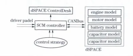
Fig.7 Real-time simulation platform
The strategy algorithms are built in the single chip microcosm(SCM)system,and the A/D module connects the driver platform and SCM.The control system communicate with the dSPACE code by CAN bus.Fig.8 is simulation result of vehicle velocity,which is determined by driver real-time operation.

Fig.8 Vehicle velocity simulation
Fig.9 is the simulation of Sband the battery discharging current Ib.When vehicle came into regeneration stage,Ibbecame negative and Sbascended.Power of EG group and motorsare shown in Fig.10.Fig.11 expresses the motors torque Tmand rotate speed nm.
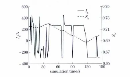
Fig.9 Simulation of Sband Ib
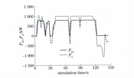
Fig.10 Power of engine and motors
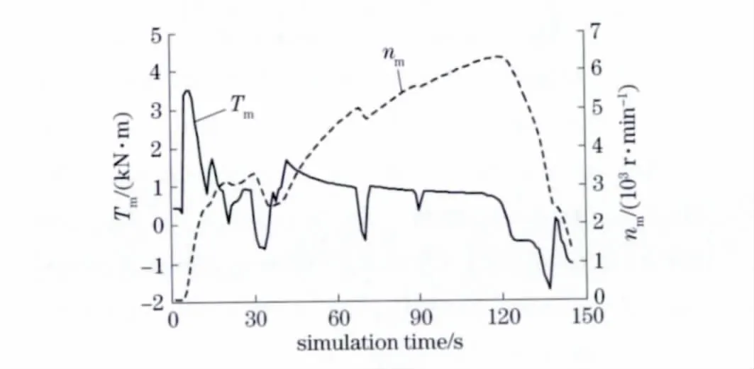
Fig.11 Motor torque and rotate speed
When themotors’powerrequirementis high,EG group works at Paand battery discharges to assist the EG group.When the motors’power requirement is relatively low,the battery begins charging and the SOC of battery is ascending.
5 Conclusions
①Fuzzy logic can be used to build the control strategy conveniently to solve the power distribution problem of hybrid tracked vehicle.
②The real-time simulation platform for hybrid electric vehicle based on dSPACE system is convenient for studing the control strategy.
③Real-time simulation results show that the presented control strategy based on fuzzy logic is correct and effective.
[1] Kessels J T.Online energy Management for Hybrid Electric Vehicles[J].Transactions on Vehicular Technology,2008,57(6):3428 -2440.
[2] Murphey Y L,Chen Z H,Kiliaris L.Intelligent power management in a vehicular system with multiple power sources[J].Journal of Power Sources,2011,196(2):835-846.
[3] Yoo H,Sul S K,Park Y,et al.System integration and power-flow management for a series hybrid electric vehicle usingsupercapacitors and batteries[J].Transactions on Industry Applications,2008,44(1):108-114.
[4] Johannes S.All electric combat vehicles for future applications,RTO TR-AVT-047[R].Berlin:NATO,2004.
[5] Liu J,Peng H.Modeling and control of a powersplit hybrid vehicle[J].Transactions on Control Systems Technology,2008,16(6):1242 -1251.
[6] Behrooz M,Emadi A M.Dual-mode power-split transmission for hybrid eElectric vehicles[J].IEEE Transactions on Vehicular Technology,2010,59(7):3223-3232.
[7] Namwook K,Sukwon C,Peng H.Optimal control of hybrid electric vehicles based on pontryagin’s minimum principle[J].IEEE Transactions on Control Systems Technology,2011,19(5):1279 -1287.
[8] Markel T,Brooker A,Hendricks T.Advisor:a systems analysis tool for advanced vehicle modeling[J].Journal of Power Sources,2002,110:255 -266.
[9] Fang L C,Qin S Y.Optimal control of parallel hybrid vehicles based on theory of switched system[J].Asian Journal of Control,2006,8(3):274 -280.
[10] Chen Qingquan,Sun Fengchun.Modern technology of electric vehicle[M].Beijing:Publishing Beijing Institute of Technology,2002.(in Chinese)
 Journal of Beijing Institute of Technology2013年2期
- Journal of Beijing Institute of Technology的其它文章
- Temperature field simulation technology for thermostat electromechanical systems
- Weight distribution of sub-munitions fuze design
- Analysis of vehicle powertrain dynamic performance
- Roundness error evaluation by minimum zone circle via microscope inspection
- Strategy to control crawling vehicles with automated mechanical transmission
- Experimental study on durability fracture behavior and vibration modal sweep for vehicle rear axle