
Research on performance testing of radio fuse based on virtual separation technology
2013-12-20 07:22XUAiguo许爱国JIALixin贾立新YANGJinwei杨晋伟JIANGZhibao姜志保
关键词:爱国
XU Ai-guo (许爱国), JIA Li-xin (贾立新), YANG Jin-wei (杨晋伟), JIANG Zhi-bao (姜志保)
(1. The People's Liberation Army 63908 Unit, Shijiazhuang 050000, China; 2. Beijing Martial Delegate Agency, Beijing 100042, China; 3. Shanxi Huaihai Industry Group Company, Changzhi 046012, China)
Research on performance testing of radio fuse based on virtual separation technology
XU Ai-guo (许爱国)1, JIA Li-xin (贾立新)2, YANG Jin-wei (杨晋伟)3, JIANG Zhi-bao (姜志保)1
(1. The People's Liberation Army 63908 Unit, Shijiazhuang 050000, China; 2. Beijing Martial Delegate Agency, Beijing 100042, China; 3. Shanxi Huaihai Industry Group Company, Changzhi 046012, China)
The conception of virtual separation technology about high/low frequency of electronic module was put forward based on the analysis of tactical performance testing of radio fuse. By means of the principle of fuse Doppler signal acquisition and injection, the high/low frequency of electronic module was virtually separated, and one of important parameters—burst height of radio fuse is tested precisely.
virtual separation; tactical performance; electronic module; Doppler signal acquisition and injection
CLD number: TN911.7 Document code: A
0 Introduction
The emergence of radio fuse is a very important innovation for the development of fuse technology. Because radio fuse can greatly improve fuse warhead coordination, it has attracted more attention from many countries all over the world and has been equipped in the troops. The property of fuse will be changed in the process of storage, especially, the damage effect will be seriously influenced by change of burst height, so it is be tested in this paper.
Usually, burst height is measured through target test, which will consume huge manpower, material resources and financial resources. In this paper, the burst height of fuse is measured by testing electronic components of radio fuse under laboratory conditions, which can not only greatly reduce the test cost, but also meet the needs of scientific research and production. Furthermore, it can provide a new method for design and property improvement of production.
1 Testing principle
The electronic devices of radio fuse generally consist of detector and signal processor. The Doppler signals are outputted by the relative motion of detector and target. The displacement and velocity in Doppler signals can be extracted by signal processing circuit, which timely outputs ignition signal pulse to explode the projectile[1,2].
Doppler frequency of the fuse aiming at the ground is proportional to fall velocity of the projectile, and amplitude is inversely proportional to height from the ground, which has nothing to do with the fall velocity. Because it is difficult to collect the signal when the missile is approaching to the target, we use a kind of method that high speed is simulated by low speed to obtain the Doppler signal, only frequency of which is different from that of the actual Doppler signal after accelerated through computer. And then the collected Doppler signal of low frequency is simulated into the Doppler signal in the real environment. Sequently, the signal is transmitted into the processing circuit and ignition pulse is collected synchronously. Thus burst height of the fuse can be calculated from the position of ignition pulse.
2 Virtual separation of high/low frequency of electronic components
In radio fuse test, high frequency and low frequency parts are needed to be separated. But in general circumstances, the high frequency and low frequency of fuse can not be physically separated. How to virtually separate the high frequency and low frequency components to ensure the accuracy of Doppler signal acquisition and injection is related to success or failure of the test method.
After electronic components are encapsulated, there exists a detection line to facilitate the test. The Doppler signal can be directly collected from this detector line. Because it is slow, it cannot be injected into the signal processing circuit. The appropriate load must be matched in order to ensure accuracy of the Doppler signal.
There are two conditions which guarantee accuracy of the Doppler signal injection: the first is that the low Doppler signal should be accelerated to the actual Doppler signal; The second is that high frequency oscillation stops. In this way, the high frequency will not input signals to the low frequency part. The acceleration of Doppler signal is completed by the computer and the high frequency oscillation can stop by external intervention.
3 Doppler signal collection and injection[3-7]
The detector, RC coupling circuit and signal processor are responsible for collection and injection of Doppler signal. As shown in Fig.1, R0is the output impedance of detector; RLis the detector load or the input impedance of signal processor; C is the coupling capacitance; A is the point of collection and injection of Doppler signal and is connected with detection line.
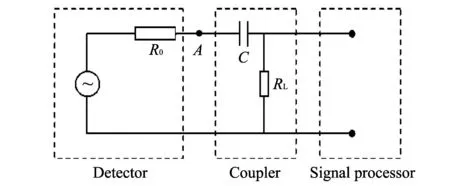
Fig.1 Local circuit diagram of electronic components
In the experiment of missile target intersection, by using the low speed to simulate the high one, the fall speed of testing missile is 100 times less than that of actual missile target intersection. Doppler signal frequency fdis extremely low. The capacitance impedance of C is 100 times larger than that of actual missile target intersection. RLand C can not play a role in normal coupled signal, therefore Doppler signal can not be transmitted to signal processor, at the same time, detector load changes from original RLto ∞(see the following calculation). Therefore, the signal amplitude at point A is different from the amplitude of missile target intersection. If the signal is extracted from point A at this time, a large error will be produced. Thus, R1and C1are paralleled between A and the ground not to damage the original workload of the detector. As shown in Fig.2, let R1=RL,C1=100C, the load of detector can be simulated by paralleled R1and C1branch circuit under the condition of actual missile target intersection, and Doppler signal can be extracted from point B. This can ensure validity of the Doppler signal collection when missile and target intersect at a low speed. At the same time, the Doppler signal extracted from point B is a pure AC signal and DC component at point A is blocked up, so it is advantageous to the signal collection and transformation.

Fig.2 Principle diagram of Doppler signal collection with slow speed
The slow Doppler signal is accelerated by a computer. When the frequency increases, the accelerated Doppler signal should be constructed, and mean while the accelerated Doppler signal could be injected from point A into the signal processing circuit. As shown in Fig.3, if power of the accelerated Doppler signal has no inner resistance, the signal amplitude will not distort; if the waveform generator of hp33120A is used as a signal source, as the resistance of hp33120A is 50 Ω, the signal amplitude at point A will decrease. When the actual signal is injected, the waveform at point A must be measured and modified to ensure that the accelerated Doppler signal by injection is consistent with low Doppler signal by collection.
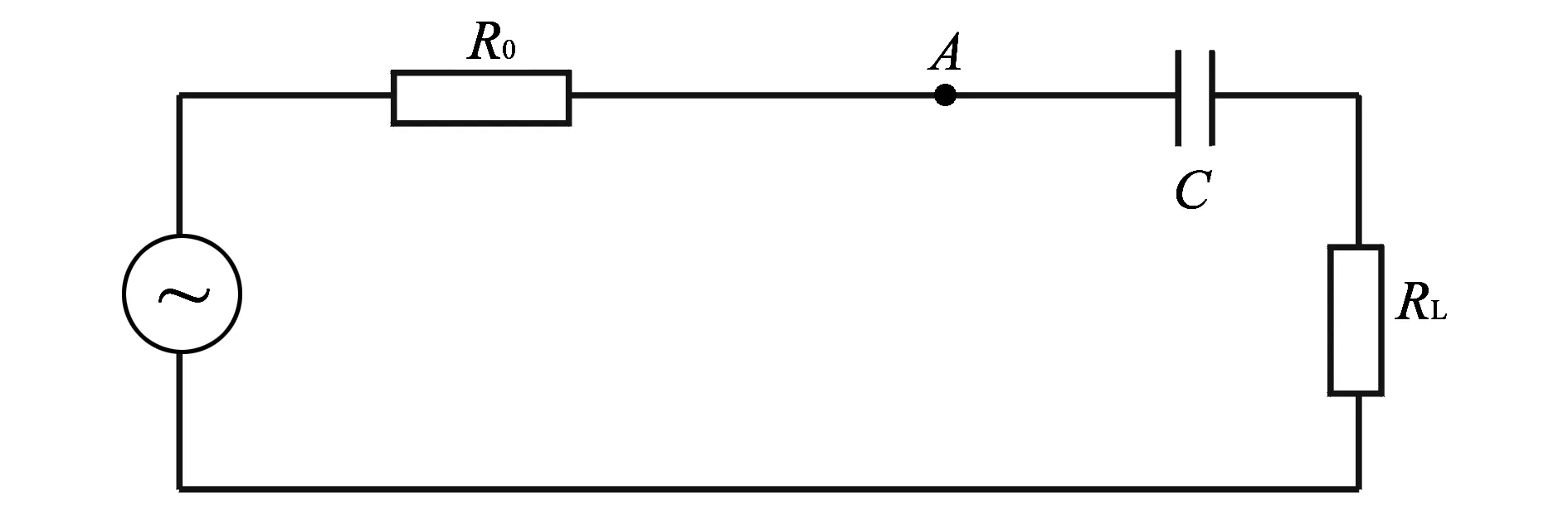
Fig.3 Testing principle diagram of Doppler signal injection
Due to power-sharing of the detector and the signal processor in electronic components, when the signal processor is injecting signal from the outside, the detector will inject signal to signal processor at the same time. Superposition of the two signals may cause inaccuracy of burst height test. Solution of this problem is to make the vibration of detector stop. It has been proved to be achievable that the vibration of the detector can stop by external intervention from electronic components.
It can be seen from the above analysis that the key technologies of collection and injection of Doppler signal are impedance matching, oscillation stop of the detector and error correction due to resistance of signal source.
The transmission efficiency of radio fuse resistance capacity coupler is calculated in the following, taking the XX fuse for an example.
The complex impedance of the detector is
where RL, C and fdare given, and fdis the Doppler frequency when the actual missile and target intersect. Thus the voltage transfer coefficient can be calculated as K=97.8%-99.9%.
It can be seen that the transmission efficiency of resistance capacity coupler is very high when missile and target intersect.
In the simulation test of missile target intersection, the Doppler signal requency is
where VRis the fall velocity of test bomb, it is equal to 0.76 m/s; λ0is electromagnetic radiation wavelength of the detector.
The voltage transmission coefficient can be drawn by the same principle, namely,
K′=4.7%.
Therefore, the transmission efficiency of resistance capacity coupler is very low when the high speed test of missile and target intersection is simulated by low speed test.
4 Method of stopping oscillating during Doppler signal injection
To stop oscillating of high frequency is to make the oscillating condition fail. Judged from the circuit principle diagram, there are two possible methods: the first method is to change the parameters R,L and C of the oscillation circuit to make it stop working; The second method is to change the DC working condition of triode and make it deviate from the linear region to the status of saturation or cutoff, which is the best method to make it enter cutoff status. The possible solution is to increase the detection line voltage VDEC. When Ve>Vb, the triode enters the cutoff status.
It has been proved that for the XX1 fuse, when DC component of Doppler signal VDC=6.0 V (VDEC=5.05 V), high frequency can reliably stop oscillating; For the XX2 fuse, when DC component of Doppler signal VDC=4.0 V (VDEC=3.36 V), high frequency does the same.
The power check on resistor R3is carried out as
P(R3)=VDEC(>R3)=5.052/270=0.094(W).
The design power of R3is 0.125 W, which is greater than P(R3)=0.094 W.
The power of R3is not too large. So the method is feasible, which makes Doppler signal contain DC component to stop oscillating.
For XX1, VDC=6.0 V, when internal resistance of signal source is 50 Ω and VDECis 5.05 V.
For XX2, VDC=4.0 V, when internal resistance of signal source is 50 Ω and VDECis 3.36 V.
5 Testing method of Doppler signal injection
Because the output circuit of Doppler signal source is a voltage follower consisting of the integrated amplifier, the internal resistance of which is very little, it is generally less than 5 Ω, therefore, the error caused by internal resistance of Doppler signal source can be ignored.
If signal generator hp33120A is used, internal resistance of which is 50 Ω, the load of signal generator will be composed of the parallel connection of output resistance of the detector and the input resistance of signal processor, and the amplitude of hp33120A output signal will decline. For the compensation of the error, the correction coefficient K is added when the waveform is defined by the software, keeping the waveform amplified by K times.
After the test, correction coefficient K of XX1 fuse is 1.41.
6 Test results
The tactical property parameters, especially burst height, of radio fuses XX1 and XX2 are tested under the experimental conditions. To evaluate the accuracy of test results, taking the same batch of products as samples, the test results of the tactical property test are compared with those of shooting range test, as shown in Table 1.

Table 1 Comparison of the test results of tactical property test with those of shooting range test
7 Conclusions
1) The tested burst height of radio fuse under the laboratory conditions meets the required demands of 0.5-30 m, thus it is a useful method for design and performance improvement of the product.
2) Comparison results of shooting range test and tactical property test proves that the high test accuracy can be obtained by using the tactical property test of radio fuse to simulate that of shooting range test and the result is reliable.
3) It should be pointed out that the accurate results of actical property test of radio fuse under experimental conditions can be got only on the condition that the effects of human factors and environmental factors should be eliminated.
[1] QIAN Yuan,GUO Ying. Research of fuze signal processing modular based on technology of DSP. Journal of Projectiles Rockets, Missiles and Guidance, 2006, 26(3): 269-271.
[2] CHEN Zhao-hui,GUO Dong-min,ZHANG Fei-peng. Impact prior radio fuze signal processing technology based on DSP. Journal of Detection and Control, 2006, 28(4): 52-54, 57.
[3] XI Xiao-hui,ZHANG Zhi-jie,WANG Wen-lian. Detonating control system based on PIC MCU. Chinese Journal of Scientific Instrument, 2006, 27(z3): 89-92.
[4] WANG Xue-dong,YANG Guang-de. Several frequency measuring methods in digital receiver. Communications Technology, 2003, (9): 16-19.
[5] Chang C I, JI Bao-hong. Fisher's linear spectral mixture analysis. IEEE Transactions on Geoscience and Remote Sensing, 2006, 44(8): 2292-2304.
[6] YANG Xue-zhi, Pang G K H, Yung N H C. Discriminative training approaches to fabric defect classification based on wavelet transform. Pattern Recognition, 2004, 37(5): 889-899.
[7] Seker S, Ayaz E. Feature extraction related to bearing damage in electric motors by wavelet analysis. Journal of the Franklin Institute, 2003, 340(2): 125-134.
date: 2013-09-12
XU Ai-guo (jxjsyjsxag@126.com)
1674-8042(2013)04-0339-04
10.3969/j.issn.1674-8042.2013.04.008
猜你喜欢
湘潮(上半月)(2022年7期)2022-12-06
公民与法治(2022年5期)2022-07-29
黄河之声(2021年9期)2021-07-21
中原商报·科教研究(2021年5期)2021-03-23
少先队活动(2020年11期)2020-12-28
中国漫画(2018年3期)2018-12-05
中国漫画(2018年1期)2018-12-05
中国漫画(2017年10期)2018-01-25
青年歌声(2017年9期)2017-03-15
 Journal of Measurement Science and Instrumentation2013年4期
- Journal of Measurement Science and Instrumentation的其它文章
- A 4-layer method of developing integrated sensor systems with LabVIEW
- Calibration and compensation methods of installation error of electronic compass
- Design of shared bus DSP board in vector network analyzer
- Error modeling and analysis of inclinometer based on digital accelerometer
- Analysis of condition monitoring methods for electromotor on oil platform
- U disk recorder based on CH376 and ATmega 128