
Microwave Photonics for Modern Radar Systems*
2014-04-24 10:53PanShilong潘时龙ZhuDan朱丹ZhangFangzheng张方正
Pan Shilong(潘时龙),Zhu Dan(朱丹),Zhang Fangzheng(张方正)
Key Laboratory of Radar Imaging and Microwave Photonics,Ministry of Education,College of Electronic and Information Engineering,Nanjing University of Aeronautics and Astronautics,Nanjing,210016,P.R.China
1 Introduction
The modern use of radar is highly diverse,including air traffic control,radar astronomy,marine radars for locating landmarks and other ships,aircraft/vehicle anticollision systems,outer space surveillance and rendezvous systems,meteorological precipitation monitoring,altimetry and flightcontrolsystems,ground-penetrating radar for geological observations,and military systems for wide-area search,target tracking,and fire control[1].Several of the above functions may be required in a single platform.However,due to the different requirements of frequency band,bandwidth,waveform,and signal processing methodology,most of these functions can only be implemented using an independent electromagnetic system.This presents a lot of problems,including increased weight and size,increased antenna blockage,electromagnetic interference(EMI),increased radar cross section,and maintenance issues because each system has its own unique set of spare parts,operators,and repair personnel[2].Fig.1 shows the block diagram of a typical radar system,consisting of local oscillators(LOs),waveform generators,modulators,filters,mixers,amplifiers,antennas,analog-to-digital converters(ADCs),signal processors,computers,and power supplies.If most of these components can be shared by the radars with different functions(usually at different frequency bands),multifunction radar with reduced space,weight,power,cost and demands for human operators is possible[3].However,it is very difficult for the state of the art electronic technologies to operate the microwave components in multiple frequency bands without sacrifice of the performance.In addition,the calibration of the system would be a critical issue because the electrical devices always have different insertion losses, phase shiftsand reflection coefficients in different fre-quency bands.To solve these problems,many microwave technologies were developed,ranging from the multiband mixers[4],receivers[5],transceivers[6]to detectors[7]and antennas[8,9],but all of them were realized at the expense of significant increase of the weight,size,complexity,EMI or power consumption.
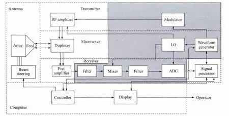
Fig.1 Schematic diagram of a typical radar system
On the other hand,microwave photonics,which brings new opportunities to revolutionize the microwave components and systems,has evolved significantly in scope and technical maturity over the past 30 years[10].As defined by many pioneers in this area[10-14],microwave photonics is an interdisciplinary field that studies the interactions between microwave and optical waves for the generation,processing,control,distribution and measurement of microwave,millimeter-wave and THz-frequency signals.Table 1 lists several key aspects of the performance difference between the conventional microwave system and the microwave photonic system.Thanks to the broad bandwidth,low loss,light weight,flat frequency response,and immunity to EMI provided by the photonic technologies,microwave photonics may allow innovative implementation of the multiband reconfigurable radar with significant added values.
Previously,there were considerable efforts devoted to applying the fast developing microwave photonic technologies to the radar systems,which can date back to the early 1990s[15-27].Examples include the trials to construct phased array radar based on photonic true time delay and the proposals to build photonic radio-frequency(RF)front-end.In 2009,the European Research Council(ERC)granted a project entitled“Photonic-based full digital radar”(PHODIR,Dec.2009—Dec.2013),focused on the study,design and re-alization of a full digital transceiver radar demonstrator based on photonic technology both for signal generation and for RF received signal processing[28].A photonic radar was built and demonstrated in a field trial at the port of Livorno,Italy.Based on PHODIR,another project“Pre-industrial photonic-based radar design”(PREPARE)was set up recently,aimed to address the research on the specific application for the airport security,providing a pre-industrial design.Meanwhile,the Europe seventh framework programme(FP7)established a project named GAIA(Photonics front-end for next-generation SAR applications,Oct.2012—Oct.2015),to develop the photonic technologies required in future array antenna systems for the implementation of the next generation synthetic-aperture radar(SAR)applications for future Earth observation missions[29].

Table 1 Performance comparison between conventional microwave system and microwave photonic system
In this paper,techniques developed in the last few years in microwave photonics that might change the way to design modern radar systems are reviewed.The recentadvancesin optoelectronic oscillators(OEOs),arbitrary waveform generation(AWG),photonic mixing,phase coding,filtering,beamforming,analog-to-digital conversion,and stable RF signal transfer are described.Challenges in implementation of these components and subsystems for meeting the requirements of the radar applications are discussed.
2 Optoelectronic Oscillator
The ability of modern radar to detect low target signatures in clutter and hostile jamming environment is highly dependent on the quality of the transmitted signal,the receiver,and the data processing[30].As an essential part in the modern radars(as shown in Fig.1),a microwave generator not only determines the quality of the RF signal in the transmitter and the intermediate frequency(IF)signal in the receiver,but also serves as a time standard for signal processing modules,by which,for example,the signal delay is measured to extract the range information.In modern radar systems,the phase noise of a microwave source is one of the key performance limiting factors[31,32].Due to the phase noise,weak targets would be hidden by strong unwanted echoes even if the echo from the target has Doppler shift.The spurious level is another key parameter of the microwave source which should be carefully considered in the radar systems.Without the high side mode-suppression ratio(SMSR),the false alarm probability will be significantly increased.
Thanks to the capability of ultra-low phase noise microwave signal generation,OEOs[33,34]have received much attention for potential radar applications in the past two decades.Fig.2 shows the schematic diagram of a typical OEO,which is a feedback loop consisting of an intensity modulator,a high-Q optical storage element(e.g.a length of fiber),a photodetector(PD),an electrical amplifier,an electrical bandpass filter(EBPF),and an electrical phase shifter.When a continuous-wave(CW)lightwave is injected into the modulator,the OEO starts to oscillate at one of its eigenmodes determined by the center frequency of the EBPF if the net gain of the loop is greater than unity.The spacing between two adjacent eigenmodes is determined by the total length of the loop.

Fig.2 Block diagram of a typical OEO[34]
The phase noise performance of an OEO is directly related to the Q-factor of the loop.In general,the longer the fiber in the OEO,the lower the phase noise[34].But the flicker noise of the amplifiers,the laser relative intensity noise(RIN),the shot noise in the PD and the noise introduced by the optical reflection would create a noise floor in the phase noise spectrum.Previously,considerable efforts were de-voted to reduce this noise floor.By using amplifiers with lower flicker noise and high-Q filters,the phase noise performance was improved[35].A fiber-optic implementation of the carrier-suppression technique was demonstrated to reduce the close-to-carrier noise of a triple-loop OEO[36].About 20-dB phase noise reduction at 10 Hz away from the 10 GHz carrier is realized.The laser RIN can be significantly reduced by inserting an optical power limiter after the laser,and the noise associated with the PD can be largely suppressed by operating the PD in the saturation limit.In addition,through laser frequency modulation,the noise due to the reflection in optical connectors or splices and double Rayleigh scattering in fiber can be reduced[37].
The mode selection and spurious level are determined by the EBPF in the OEO loop.For a single loop OEO,the modes close to the peak frequency will have large possibility to oscillate,and spurious will show up at these sidemodes[38].With the increasing of the fiber length,which is always adopted to improve the phase noise performance of the OEO,the mode spacing becomes narrower and the spurious level will be high,because the ability of the EBPF to remove the supermodes is always limited.By using a high-Q microwave or optical filter,the SMSR will be improved.A possible approach is to incorporate an ultrahigh-Q whispering gallery mode resonator(WGMR)in the OEO[39].A typical Q value of the WGMR is greater than 109,which can be used to select only one mode in a loop with a length of several kilometer.Another way to effectively suppress the undesired sidemodes is to apply multiple loops[37,40-43].By introducing additional fiber loops with shorter lengths in parallel with the long fiber loop,the Vernier effect would form additional filtering in the OEO cavity.For example,in a dualloop frequency-doubling OEO based on polarization modulation and polarization multiplexing[43],a SMSR of 78 dB is realized for a fundamental microwave signal at 9.95 GHz or a frequency-doubled signal at 19.9 GHz.In addition,a section of unpumped EDF in a coupled OEO(COEO)[44]can serve as a mode-restricting device through spatial hole burning effect,which can also significantly improve the SMSR of the OEO.
Frequency hopping is widely used in modern radars,thus fast and wideband tunability of the microwave source is also required.The tunability of the OEO can be realized by incorporating a tunable EBPF in the loop[35,45].But the frequency tuning range is limited due to the electronic bottle neck.To overcome the problem,a frequency-quadrupling OEO was reported,in which the frequency-quadrupling structure in the output branch improves the tuning range by four times[45].Another way to realize tunable OEOs is to form a tunable microwave photonic bandpass filter in the OEO loop[46-51].For example,a widely tunable OEO was reported based on a tunable microwave photonic filter formed by a polarization modulator(PolM)and a chirped fiber Bragg grating(FBG)together with a polarization beam splitter(PBS)[50].The chirped FBG serves as a dispersive element(DE).By changing the polarization state between the PolM and the PBS,simultaneously amplitude modulation and phase modulation with the ratio between them adjustable are formed,which leads to a shift of the transmission response.In this way,a tunable microwave photonic filter is formed to realize a coarse selection of the oscillation mode in the OEO.The dualloop configuration is used to achieve the fine frequency tuning.A tuning range of 5.8—11.8 GHz is realized.In addition,an interesting tunable OEO based on the stimulated Brillouin scattering(SBS)effect was reported to convert a low-quality and low-frequency IF signal to a high-quality and high-frequency signal without introducing any high-Q electrical filter[52].A single-sideband suppressed-carrier modulated signal generated by modulating a poor-quality IF signal is used as the Brillouin pump wave,and a phase-modulated signal at the same wavelength is used as the probe signal.A high-Q microwave photonic filter realized by the selective amplification of the SBS effect is used for mode selection in the OEO.By tuning the Brillouin pump wave,a wide tuning range is realized.High quality microwave signals from 10.15 to 42.15 GHz are experimentally generated by applying low quality IF signals.
Another strict requirement of the microwave source in the modern radars,especially the airborne and space-based radars,is small size and low power consumption.A lot of works have been done to reduce the size of the OEO.One way is to replace the long fiber in the OEO loop by high-Q optical resonators,which could be WGMRs[34,53,54]or fiber ring resonators[55,56].With the high-Q WGMRs,OEOs in a package smaller than a coin can be realized without sacrifice of the performance[34].However,optical coupling and wavelength alignment will be very difficult,and sophisticated circuits should be employed to make the OEO work stably.By using a directly modulated laser(DML)to replace the laser source and the intensity modulator,one device and its related control circuit can be saved to reduce the OEO size[57,58].However,the DMLs under large signal modulation would lead to a broad linewidth of the optical carrier,resulting in poor phase noise performance.To further reduce the size of the OEO,a compact OEO based on an electroabsorption modulated laser(EML)was proposed[59].The EML can replace the laser source,intensity modulator and PD,so that the OEO can be miniaturized by saving two devices and the corresponding drive circuits.The phase noise with the generated 9.945 GHz signal is-101.31 dBc/Hz,showing that the compact OEO has an acceptable performance.
3 Photonic Arbitrary-Waveform Generation
For a radar system,the properties of the signal emitted by the antennas,such as the power,the temporal waveform,and the spectral bandwidth,will determine the detection range,resolution,and the antiinterference ability.In modern radar systems,programmable and diverse complicated waveforms are needed to increase the resolution and meet the fastswitching requirements,thus,AWG is becoming more and more important.In the current stage,the most commonly used electrical AWG in a radar system is realized by the direct digital frequency synthesis(DDS)[60].The DDS technology offers great flexibility for switchable waveform generation,but it suffers from the limited operation bandwidth which is usually lower than a few GHz.Because the radar systems are evolving towards working at high frequency and large bandwidth,optical arbitrary waveform generators(OAWGs)become a promising solution because it can generate high frequency and large bandwidth waveforms through optical technologies and then convert the optical signal into electrical arbitrary waveforms for radar applications.Besides the huge bandwidth,OAWG also features low cost,low loss and immunity to EMI,etc.Up to now,several kinds of OAWG have been successfully demonstrated,showing the great potential for their use in radar systems.
An OAWG can be realized by optical spectral shaping followed by frequency-to-time mapping(FTTM)[61].Fig.3 shows the fundamental principle of this method.The system is usually composed of a pulsed laser source,an optical spectral shaper,a DE and a PD.The spectrum of the pulsed laser source is modified by the optical spectral shaper.Then,FTTM is performed in the DE,which can be a length of dispersive fiber or a chirped FBG.Mathematically,the impulse response of a DE is[62]
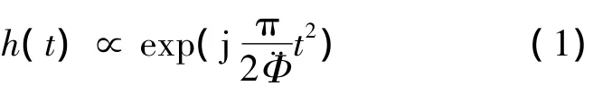
where¨Φ is the second-order dispersion of the DE.If the temporal width Δt0of the input pulse ain(t)is small enough to let|Δt20|≪|2π¨Φ|,the output signal after the PD is[63]
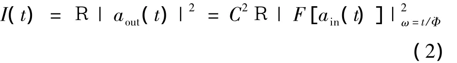
where C is a constant and F denotes the Fourier transformation,R is the responsivity of the PD.As can be seen from Eq.(2),the generated electrical signal is a scaled version of the input optical power spectrum.As a result,by designing the optical spectral shaper with arbitrary power transfer function,arbitrary waveform can be generated.
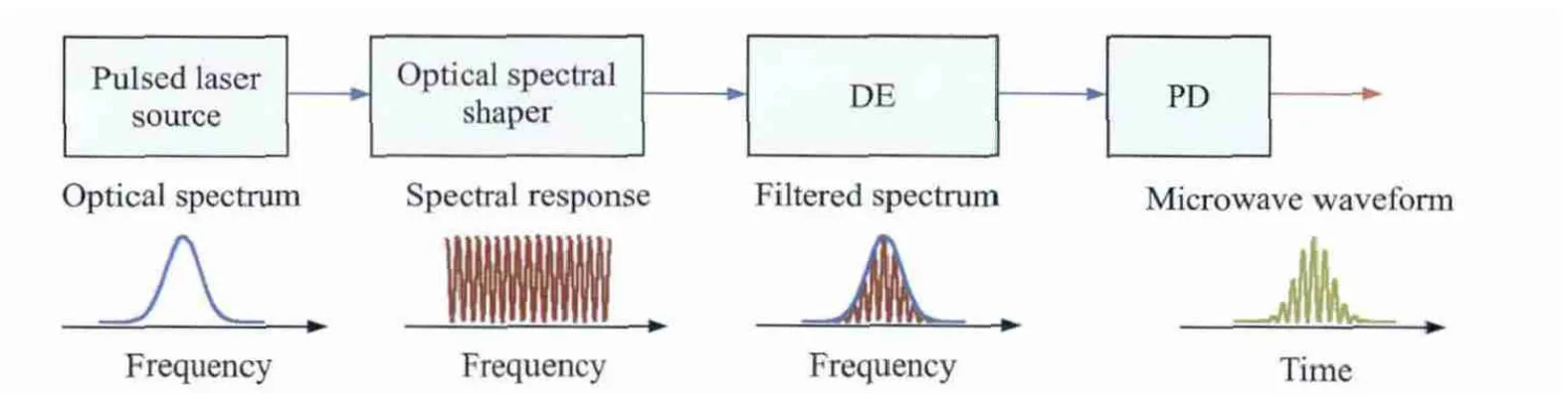
Fig.3 Schematic diagram for waveform generation based on optical spectral shaping and FTTM
The key component in an OAWG based on spectral shaping and FTTM is the optical spectral shaper,which can be implemented based on free-space optics[64]or fiber optics[65-67].Fig.4 shows the structure of a typical optical spectral shaper,where the input optical pulse is first dispersed spatially by a grating and a spatial light modulator(SLM)array is used to implement optical spectral shaping before the dispersed light is combined by another grating.The advantage of using an SLM for spectral shaping is that the spectral response of an SLM can be updated in real time,making the generation of an arbitrary waveform possible.The main limitation of a free-space-opticsbased spectral shaper is the large size and high loss.In addition,the coupling between fiber to free-space and free-space to fiber makes the system complicated.On the other hand,a spectral shaper can be implemented based on fiber optics.A fiber-optic spectral shaper has the advantages of smaller size,lower loss,and better compatibility with other fiber-optic components.For instance,a scheme for the generation of frequency and phase tunable pulsed microwave waveform based on spectral shaping and FTTM through all fiber optics is demonstrated with the schematic diagram shown in Fig.5(a).The optical spectral shaper is a tunable optical comb filter consisting of a differential group delay(DGD)element,a PolM and a polarizer[68].By passing a short optical pulse through the tunable comb filter and a DE,a pulsed microwave signal is generated after optical-to-electrical conver-sion.The phase of the generated microwave signal can be continuously tuned by tuning the voltage applied to the PolM,as shown in Fig.5(b).Thanks to the large bandwidth of the PolM,phase modulation of the microwave signal as high as tens of GHz can be achieved.Besides,the frequency of the microwave signal can be tuned by changing the DGD and/or the dispersion of the DE,as shown in Fig.3(c).

Fig.4 Optical spectral shaper based on free-space-optics[63]
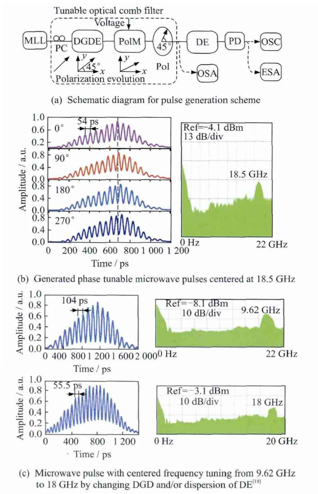
Fig.5 Schematic diagram for pulse generation and the experimental results
Another method for OAWG is Fourier pulse shaping based on an optical frequency comb(OFC).By manipulating the OFC to have certain amplitude and phase properties corresponding to the Fourier transformation of the target pulse waveform,the target waveform can be obtained in the time domain[69].The key issues for OAWG by Fourier pulse shaping is the generation of a wideband OFC and manipulating both the amplitude and the phase of the OFC.A mode locked laser(MLL)can generate an OFC with a comb line spacing being the same as the temporal interval between adjacent short pulses in the time domain[70].This method for OFC generation suffers from poor stability and a high cost,and it is also hard to obtain a flatted spectrum.A cost-effective approach to generating a stable and flat OFC is to modulate a CW light by electro-optic modulators[71,72].The flatness of the obtained OFC can be less than 1 dB in the power spectrum[71].To complete the Fourier pulse shaping based on the generated OFC,an optical processor that can manipulate the amplitude and phase of the comb is necessary.There have been commercially available optical processors that can perform this task,and the principle is almost the same as that shown in Fig.4.
Wehave recentlydemonstrated an OAWG scheme based on Fourier pulse shaping[73].The OFC is generated by modulating a CW light through an electro-absorption modulator(EAM)and two cascaded electro-optic phase modulators(PMs),which has a comb line spacing of 40 GHz,3 dB bandwidth of 3.8 nm and an optical signal-to-noise ratio(OSNR)of 40 dB.Then,using a commercially available programmable optical processor(Finisar Waveshaper-4000S)with a spectral resolution of 1 GHz,Fourier pulse shaping is implemented by designing the transfer functions of the optical processor according to the Fourier transformation of the target waveform.40 GHz square pulse,triangular pulse and parabolic pulse are experimentally generated.
4 Photonic Microwave Mixing
Microwave mixing for frequency upconversion and downconversion is a basic function of transmitters and receivers in modern radar systems.In the transmitter,to generate an RF signal at the desired frequency band,a frequency upconversion is usually needed,while at the receiver site,being restricted by the bandwidth of the ADC and digital signal processing(DSP)unit,the received RF signal should be downconverted to the baseband or IF band.The microwave mixer should have large bandwidth,high conversion efficiency,high isolation and low distortion,to meet the critical requirements of the future multifunction radar systems.Photonic microwave mixer can potentially provide all the above features as well as the immunity to the EMI.
Previously there were many methods proposed to achieve photonic microwave mixing,which can be generally divided into two categories:(1)the electrooptical approaches based on direct modulation and/or external modulation[74-84],(2)the all-optical approaches based on the nonlinear effects of a semiconductor optical amplifier(SOA)[85-87].
The electro-optical approach was first investigated by Kolner and Dolfi in 1980s by using Mach-Zehnder modulators(MZMs)[74].By sending two signals to the RF port of an MZM,the photonic microwave mixing is realized thanks to the large nonlinearity of the MZM when biased at the maximum transmission point.The photonic microwave mixing can also be implemented by two MZMs placed in serial,with one MZM to perform the electrical to optical conversion,and the other one to realize electro-optical mixing.The bandwidth of the MZM-based photonic mi-crowave mixer can be more than 40 GHz,limited only by the bandwidth of the MZMs and the PDs,but the conversion efficiency is relatively low,which was-60 dB for single-MZM approach and-72 dB for series-MZM approach[75].To increase the conversion efficiency,one promising way is to apply large optical power.When the input optical power is increased to 1 W,the conversion efficiency can reach -34 dB[76].To further increase the conversion efficiency,other optical amplification method is of great interest.For example,by introducing SBS amplification in the MZM-based microwave photonic mixer,a conversion efficiency of about -25 dB or -7 dB was achieved[77,78],and the SFDR was measured to be 89.5 dB·Hz2/3.PM can also be used to realize photonic microwave mixing.As compared with the MZM-based approach,the use of a PM may have the advantages in terms of low insertion loss,high linearity and bias-drift-free operation.Since the phase-modulated signal cannot be detected directly by a PD,mechanisms for performing phase modulation-to-intensity modulation(PM-IM)conversion must be introduced.An effective way to implement the PM-IM conversion is to remove the optical carrier by an FBG[79].The conversion gain based on series PMs with a FBG can reach 2.64 dB.In addition,by suppressing the optical carrier,the linearity of the mixer is significantly improved,resulting in an SFDR of 114 dB·Hz2/3.The anti-Stokes notch introduced by the SBS effect can also be used to remove the optical carrier[80].With the assistant of an Erbium doped fiber amplifier(EDFA),the conversion gain is as high as 11.3 dB.
In addition to the serial-modulator structure,the parallel-modulator structure is also of great interest,because the parallel structure can effectively suppress the modulation distortion in the electro-optical modulators.For example,the spurs of the photonic microwave mixer realized by placing the MZMs in parallel are significantly reduced to about-84 dBc at 100 MHz IF[81].By placing PMs in a Sagnac loop,which is principally a parallel structure since the clockwise and anti-clockwise lights are combined at the output of the loop to remove the optical carrier,a conversion gain of 9 dB and an SFDR of 115 dB·Hz2/3are achieved,respectively[82].With the commercialization of integrated dual-parallel MZM(DPMZM),a compact high performance photonic microwave mixer can be easily implemented[83].By properly setting the bias voltages of the DPMZM,the optical carrier can be suppressed,a high conversion gain of 10.1 dB and a high SFDR of 115.6 dB·Hz2/3are achieved with the assistance of the EDFA.
Thanks to the various nonlinear effects in the SOA,such as cross-phase modulation(XPM)[85],cross-gain modulation(XGM)[86]and four-wave mixing[87],an SOA is another promising device for implementing optical mixing.For SOA-based mixer,both of the signals for mixing are optical.Compared with the high speed electro-optic modulators,the SOA has a relatively low bandwidth due to the relatively slow gain recovery in the SOA.However,most of the SOA-based methods are polarization insensitive,which can reduce the system cost since no adaptive polarization controlling is needed.
Recently,we proposed a polarization-insensitive photonic microwave down converter based on parallel MZMs and a balanced photo receiver[88],as shown in Fig.6.By biasing the MZMs at the transmission points on the opposite linear slopes,the performance of the proposed photonic microwave downconverter is almost independent of the polarization state of the input optical microwave signal to be down-converted.The measured polarization dependent loss(PDL)is less than 0.06 dB.We also proposed a compact photonic microwave mixer based on a single dual-drive MZM[89].The LO and RF signals are sent to the two RF ports of the dual-drive MZM,respectively.By biasing the modulator at the minimum transmission point,a downconverted IF signal without RF and LO leakage is obtained.Since the modulator is biased at the minimum transmission point,the optical carrier is suppressed.Similar to Refs.[79,80,82-83],a high conversion efficiency can be achieved.
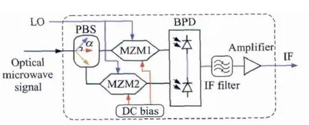
Fig.6 Polarization-insensitive photonic microwave downconverter[88]
In a photonic microwave mixer,an LO is inevitable.The quality of the LO,especially the phase noise performance,will significantly affect the performance of the entire system.Since the OEO is an attractive LO,several photonic upconversion and downconversion systems based on an OEO have been reported[90-95].For example,we recently reported a high-performance downconverter based on an OEO using a single dualdrive MZM[95].The dual-drive MZM is used to simultaneously convert the input RF signal into an optical signal,form an OEO for RF carrier extraction,and downconvert the optical RF signal to the baseband.
5 Photonic Microwave Phase Coding
For radar system,higher range resolution can be achieved with a shorter radar pulse.For a given distance,a shorter pulse needs a larger peak power,which greatly increases the difficulty for the design of the radar system since the components in the transceivers must be able to tolerate the large peak power.To overcome this problem,microwave pulse compression is widely adopted,which can be implemented by generating a linear frequency-modulated or a phasecoded signal in the transmitter and performing the cross correlation in the receiver.Since the phase-coded signals generated in the electrical domain always have limited frequency(only a few GHz),photonic approaches become attractive[96-103].
In general,phase coded signals can be generated in the optical domain by phase modulating one wavelength of a phase-correlated dual-wavelength optical signal with an electrical coding signal.For instance,a phase coded signal was generated by employing a Sagnac interferometer incorporating a PM[97].In the scheme,two±1st order sidebands are generated by biasing a MZM at the minimum transmission point,and then sent into the Sagnac interferometer incorporating a PM and a FBG which are used to modulate the incoming optical signals and reflect back the-1 sideband,respectively.As a result,only one sideband is phase modulated.In the PD,the square-law photodetection converts the phase modulation in the sideband to the generated RF signal.A phase coded signal is thus obtained.Another phase coded signal generator was reported based on a polarization-maintaining FBG and a PolM[100].In this approach,two phase-correlated wavelengths are sent into the polarization-maintaining FBG to make the two wavelengths orthogonally polarized.Then,the PolM is used to modulate the two orthogonally polarized wavelengths with complementary phase modulation.After photodetection,a phase coded microwave signal with a frequency from 40 GHz to 50 GHz is generated.The frequency is limited by the wavelength spacing between the two passbands at the two polarization axes of the PMFBG.
We have recently proposed and demonstrated a photonic microwave phase coding system using two cascaded PolMs[102].Fig.7 shows the schematic diagram.The first PolM(PolM1)incorporated with an optical bandpass filter(OBPF)is used to implement a microwave photonic phase shifter[104].The second PolM driven by an electrical coding signal is followed to control the polarization state of the optical microwave signal.Since the phase shift of the microwave photonic phase shifter is dependent on the polarization state of the optical microwave signal,the phase of the generated signal can be controlled by the electrical coding signal.The system can generate phase coded signals with a broad bandwidth(from 10 to 40 GHz)and a high coding speed(up to the modulation speed of the second PolM).
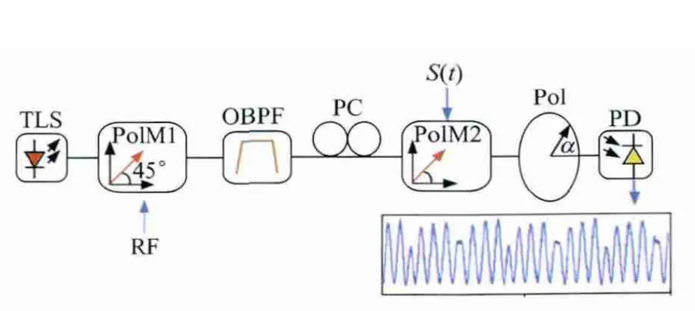
Fig.7 Schematic diagram of the phase-coded signal generator based on two cascaded PolMs[102]
All the above systems are implemented using two or more electro-optical modulators.To reduce costly and complexity of the photonic microwave phase coding system,we proposed a phase-coded signal generator based on a single dual-drive MZM[103],with the schematic diagram shown in Fig.8.The RF signal to be coded is applied to one RF port of the dual-drive MZM to generate a double-sideband phase-modulated optical signal,and the electrical coding signal is sent to the other port to control the phase of the optical carrier.After combing the two signals at the output of the dual-drive MZM,the phase of the optical carrier is mainly determined by the amplitude of the coding signal.Thus,a phase coded signal is generated after photodetection.

Fig.8 Schematic diagram of the phase coded signal generator based on one single dual drive MZM[103]
6 Microwave Photonic Filtering
In a radar receiver,a filter is inevitable to suppress the strong interference from the environment.Especially for the moving target indication(MTI)radar,a high selectivity and frequency-tunable filter can significantly reduce the dynamic range requirement of the receiver[19].However,it is very difficult to implement such high-performance filters in the electrical domain.To overcome the problem,microwave photonic filtering has been drawing particular attentions thanks to the distinct features brought by the photonic technologies,such as large bandwidth,low loss,lightweight,wide tunability,and immunity to EMI[13,21,105-107].Because of the low loss(independent of the RF signal frequency)and light weight of the optical fiber,very long time delay can be introduced to the microwave photonic filters,so the Q value of the filter can be very high.In addition,the huge bandwidth of the optical subsystem would allow the microwave photonic filters to be used for multichannel signal processing based on WDM technologies.
In general,microwave photonic filters can be classified as either a finite impulse response(FIR)filter or an infinite impulse response(IIR)filter.Due to the square-law photodetection of the PD,the microwave photonic filters usually have all-positive coefficients[108-111]which can only perform low pass filtering.To solve this problem,microwave photonic filters with one or more negative coefficients are proposed to realize bandpass filtering.Many methods were reported,including differential detection[112],complementary intensity modulations by biasing the taps at different transmission points of a MZM[113],phase modulation to intensity modulation conversion based on positive or negative dispersions[114],or polarization modulation[115].However,those microwave photonic filters always have relatively poor frequency tunability,or the free spectral range(FSR)and spectral profile would change when the center frequency is tuned.This issue can be overcome if complex coefficients are applied.The complex coefficients can be implemented using SBS in high nonlinear fibers[116],or slow light in SOAs[117].However,these systems suffer severely from the small operation bandwidth,high power consumption,or careful controlling of the wavelength and amplitude of the optical carrier.In addition,full FSR-range tunability is hard to im-plement because of the difficulties to implement the full 360°phase shifts.For example,in Ref.[118],five SOAs are adopted to obtain a full 360°tunable phase shifter.Based on a DPMZM and an OBPF,a full FSR-range tunable microwave photonic filter was reported with complex coefficients realized[119].The key limitations associated with the method are the large insertion loss,complex bias setting and the bias drifting problem of the DPMZM.Reconfigurable microwave photonic filters can also be implemented using a programmable photonic processor comprising a 2-D array of liquid crystal on silicon pixels[120].By simply adjusting the phase and amplitude of the optical spectra,the coefficients of the microwave photonic filter can be changed to arbitrary complex values.
Recently,we have reported several approaches to realize full FSR-range tunable microwave photonic filters[121,122]based on a polarization modulation based microwave photonic phase shifter[104].Fig.9 shows the multi-tap microwave photonic filter with all complex coefficients.A laser source,a PolM,three wavelength division multiplexers(WDMs),a polarization controller(PC),a polarizer and a PD are used to implement a microwave photonic phase shifter.By simply controlling the PC in each tap,the phase of the RF signal can be tuned independently in the range from-180°to 180°.Thus,the frequency response of the microwave photonic filter can be tuned over full FSR-range while maintaining the shape and FSR unchanged.
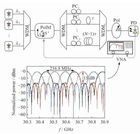
Fig.9 Schematic diagram of the multi-tap MPF with its frequency response[122]
7 Photonic Beamforming
Phased array antenna plays a significant role in modern radar systems.In the phased array antenna,beamforming network is one of the most important parts for controlling the direction of the radiated beam.Due to the intrinsic features brought by the photonic technologies,optically controlled beamforming networks(OBFNs)have attracted a lot of attentions in the past two decades[123-125].There are generally two kinds of OBFNs in the literature,i.e.the OBFN based on phase shifters and the OBFN based on true time delays.
For the phase-shifter-based OBFNs,the main advantages are the simple structure and easy operation since the beam steering is implemented by simply inserting phase shifters before the radiated elements.In 2005,Bui et al proposed an OBFN using vector-summethod based photonic microwave phase shifters[123].In the system,a variable directional coupler is used to split the optical RF signal into two paths with different fiber lengths.By controlling the coupling ratio of the variable directional coupler,the combined signal after photodetection has different phase shifts.We reported a compact phase-shifter based OBFN with all the active and costly components shared[124],as shown in Fig.10(a).A laser diode(LD),a PolM,an OBPF,a PC,a PBS and a PD work together as a microwave photonic phase shifter.By simply controlling the PC in each path,the phase of the signal in each path is independently controlled.In the experiment,beam directions of-30°,0°and 30°are obtained by a 1×4 OBFN.

Fig.10 Schema and experimental results of OBFN
The main limitation associated with the phaseshifter based OBFN is the beam squint effect,by which the main beam deviates from the desired direction as the microwave carrier frequency varies,making the system only workable for radars with small instantaneous bandwidth.To solve the problem,truetime-delay based OBFNs were proposed,which can be realized based on variable physical length[16,125-127],large DE and variable optical wavelength[128-130],slow lights and variable optical power[131,132].These approaches,however,are bulky,lossy,complex and sensitive to the environmental fluctuations,which cannot meet the requirement of many practical applications.One solution to these problems is to fabricate the OBFN on a chip[133-138].One impressive work was reported recently by Roeloffzen et al from University of Twente[136,137].To achieve continuously tunable true time delay,ring resonator-based broadband delays and coherent optical combining are applied.The bandwidth of the fabricated OBFN based on TriPleX waveguide technology covers the whole DVB-S band(10.7—12.75 GHz),and the true time delay can reach 236 ps through thermo-optic effect.The chip for 16×1 OBFN is only 13 mm×70 mm[138].
8 Photonic Analog to Digital Conversion
In modern radar systems,signals from the RF receivers are commonly processed in the digital domain.ADC is thus one of the essential components.The evolution of the radar systems are requiring ADCs with high sampling rate,large analog input bandwidth,high effective number of bits(ENOB)and low timing jitter.Satisfying the four requirements is quite a challenge for the state-of-the-art electronic ADCs[139,140].Thanks to the large bandwidth of photonic technologies and the low timing jitter of MLLs,photonic ADCs can remarkablyenhance theperformance ofthe electronic ADCs.In the last few years,extensive efforts have been devoted to the design and implementation of the photonic ADCs[139],in which signal timestretching,sampling or quantizing are realized in the optical domain.
Fig.11 shows the photonic time-stretch ADC,which consists of a photonic analog front-end preprocessor and an electronic ADC back-end[140-145].The ultra-short optical pulse with a broad spectrum from an MLL is made linearly chirped and broadened by passing through a dispersive medium.Then,an electro-optic modulator maps the temporal waveform of the input signal into the optical frequency of the chirped pulse.Through a second dispersive medium,the optical signal is further stretched in the time domain.Finally,a PD converts the stretched optical pulses to the electrical domain,providing the stretched replica of the original analog signal.The photonic time-stretch process greatly improves the equivalent sample rate of the electronic ADC and reduces the noises induced by the clock jitter.A photonic time-stretch ADC with a stretch factor of up to 250 and an equivalent sampling rate of 10 Tera-sample/s was demonstrated[141].
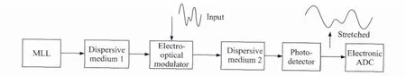
Fig.11 Schematic diagram of photonic time-stretch ADC[140]
The ultra-short pulse train from the MLL can also be used for signal sampling[146-149].As shown in Fig.12,the architecture of the photonic sampling ADC is similar to the photonic time-stretch ADC except that in the photonic sampling architecture the electronic ADC takes only one sample(the peak)in each pulse and is synchronized with the MLL.The photonic sampling ADC takes advantage of the low timing jitter of the MLL and sharply compresses the noise introduced by the clock jitter.To further improve the equivalent sample rate,multiplexing technologies in the time domain or wavelength domain can be exploited.In Ref.[149],the equivalent sample rate of the photonic sampling ADC is increased by four times using a switching matrix,which provides an ENOB of≥7 bit for a bandwidth of 40 GHz.

Fig.12 Basic structure of photonic sampling ADC[139,146-149]
Fig.13 shows a typical configuration to quantize the input analog signal in the optical domain[150-154]through multiple electro-optical intensity modulators with different half wave voltages[150],phase shift[151],or their combination[154]and an array of electronic comparers(i.e.1 bit electronic ADC).To reduce the clock jitter,some photonic quantization ADCs use ultra-short pulses from MLLs as the sampling pulses.These photonic ADCs are also called the all-optical ADCs[151].
9 Stable RF Signal Transfer

Fig.13 General concept of photonic quantization ADC[150-154]
Compared with the monostatic radar system,one of the most important and difficult problem for multistatic radar systems is the stable high-precision clock standards distribution to different bases.During the past few years,there have been a lot of works on stable RF signal transfer.Because of the immunity to the EMI,low loss and many other advantages,optic fiber is one of the best media for RF signal transfer especially for long-haul transmission.There are two primary approaches for stable fiber delivery of RF signal.The first one is using the detected phase error between a local oscillation signal and the round trip signal to control components like optical delay line and electrical phase shifter[155].This method compensates actively the phase vibration of the RF signal introduced by the fiber transmission.However,it has a limited compensation range and needs complicated driving circuits and phase error detection circuits.The other approach is to use frequency mixing to passively eliminate the phase vibration[156,157].But the scheme proposed in Ref.[156]needs three stages of frequency mixing and three LO sources with precise phase synchronization,and the scheme proposed in Ref.[157]needs even more stages of frequency mixing and a complex proportional-integral control.The large-number-stage frequency mixing would introduce problems of complicated operation,large conversion loss and severe noise.
Recently,we have proposed a compact stable fiber delivery of RF signal based on the frequency mixing approach[158]. The diagram ofthe proposed scheme is shown in Fig.14.The LO signal generated in the local station has a half frequency of that of the RF signal received in the remote antennaunit(RAU),which is converted to an optical microwave signal at MZM 1 and transmitted to the RAU via optical fiber.In the RAU,the RF signal received by the antenna is converted into another optical microwave signal at MZM 2,coupled with the microwave optical signal from the local station,and then transmitted back to the local station after being boosted by an EDFA.Assume that the time delay of the transmission system is τ,the RF signal A1from the RAU is delayed by τ(we mark this delayed signal A4),and the LO signal A2is delayed by 2τ after a round trip(the signal after the round trip is marked A3).Because A4has a half frequency but double time delay compared with A3,they have the same phase delay.Signal A3is firstly upconverted by signal A2and downcoverted by signal A4,and finally signal A6is obtained which do not have phase vibration due to the subtraction of the phase terms.In the experiment,when a 6-GHz RF signal is delivered through a 20-km SMF,the timing jitter can be effectively reduced from 56.13 ps to less than 1.9 ps by the post phase correction scheme.
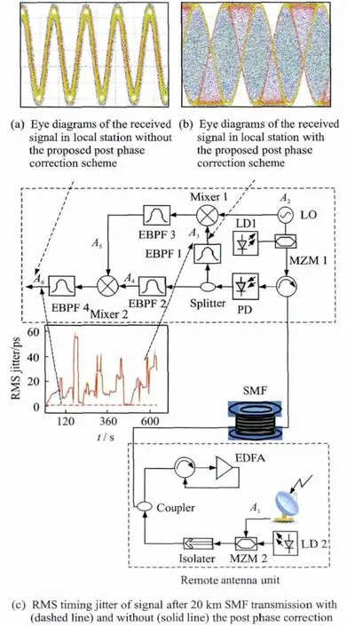
Fig.14 Schematic diagram of stable fiber delivery of RF signal based on frequency mixing and experimental results
10 Discussion and Conclusions
This paper reviewed the recent development of microwave photonics for potential applications in radar systems,with an emphasis on the following technologies that are closely related to the radar functionality and performance:OEOs,AWG,photonic mixing,phase coding,filtering,beamforming,analog-to-digital conversion,and stable RF signal transfer.These photonic technologies have been proved to have superior performance than their electrical counterparts,in terms of operation bandwidth,size,mass,and complexity,etc.Current research advances are encouraging,sufficiently showing the promising potentials of microwave photonics for radar applications,especially for future multifunctional and high performance radars.Despite the intense research activities carried out during the past three decades,there is still a considerable room for improvement.Several expected future developments are discussed as follows.
(1)The compatibility of different microwave photonic subsystems must be improved to integrate multiple microwave photonic functions in a single platform.The microwave photonic oscillators,arbitrary waveform generators,mixers,phase coders,filters,beamformers,analog-to-digital convertors are currently implemented based on different laser sources(i.e. CW,tunable,comb and pulsed laser sources),modulation schemes(i.e.phase modulation,intensity modulation,polarization modulation,and parallel or cascaded electrooptic modulation)and detection methods(i.e.direct detection,coherent detection,single-end or balanced detection).Some implementations require optical filtering,which may affect the realization of some other microwave photonic functions.The mechanism for adding tunablility or reconfigurability to some microwave photonic subsystem may also degrade the performance of other microwave photonic technologies.
(2)Continuous efforts should be devoted to the improvement of the performance of the devices and subsystems,while at the same time reducing the cost.Modern radars demand critically for large bandwidth,high sensitivity,large dynamic range of the RF systems.While microwave photonic technologies have superior performance in term of bandwidth,the sensitivity is low due to the high noise figure of the electrical-to-optical or optical-to-electrical conversion,and the dynamic range is relatively low because of the nonlinearity and low efficiency of the modulators and detectors.
(3)The microwave photonic systems must include antennas,RF amplifiers and other electronic devices or modules,but almost none of them is designed dedicatedly for the microwave photonic applications,which limits the potential of microwave photonics in practice.To solve this problem,hybrid design of the electrical and optical system is required.
(4)Most of the microwave photonic systems are realized based on discrete optical or electrical components,which is bulky,complicated,unstable,and power consuming.Photonic integrated circuit is a promising solution to this limitation.Significant advances were achieved in the past few years,and were reviewed in Ref.[159],but many microwave photonic functionalities are still not demonstrated on a chip.Therefore,more efforts to make the microwave photonic system compact,light,cheap,reliable and low power consuming are needed.
Acknowledgement
The authors realize that the time and space available for a review of such an ambitious subject are limited and,thus,regretfully,we are unable to cover many important contributions.The authors would like to acknowledge the following people for their assistance:Fu Jianbin,Huang Menghao,Zhang Yamei,Wei Juan,Tang Zhenzhou,Gu Xiaowen,Ye Xingwei,and Wu Huan,all with the Key Laboratory of Radar Imaging and Microwave Photonics,Ministry of Education,Nanjing University of Aeronautics and Astronautics.
[1] Skolnik M I.Radar handbook[M].3rd Edition.New York:McGraw-Hill,2008:1-24.
[2] Tavik G C,Hilterbrick C L,Evins J B,et al.The advanced multifunction RF concept[J].IEEE Transactions on Microwave Theory and Techniques,2005,53(3):1009-1020.
[3] Saddik G N,Singh R S,Brown E R.Ultra-wideband multifunctional communications/radar system[J].IEEE Transactions on Microwave Theory and Techniques,2007,55(7):1431-1437.
[4] Hu S,Xiong Y Z,Wang L,et al.A 77—135 GHz down-conversion IQ mixer for 10 Gbps multiband applications[C]//the 13th International Symposium on Integrated Circuits(ISIC).Singapore:IEEE,2011:29-34.
[5] Jeon S,Wang Y J,Wang H,et al.A scalable 6-to-18 GHz concurrent dual-band quad-beam phased-array receiver in CMOS[J].IEEE Journal of Solid-State Circuits,2008,43(12):2660-2673.
[6] Jain V,Tzeng F,Zhou L,et al.A single-chip dualband 22—29-GHz/77—81-GHz BiCMOS transceiver for automotive radars[J].IEEE Journal of Solid-State Circuits,2009,44(12):3469-3485.
[7] Ono H.Power saving type multi-band microwave detector[P].U.S.:Patent 53899301995-2-14,1995.
[8] Chu R S,Lee K M,Wang A T S.Multiband phased-array antenna with interleaved tapered-elementsand waveguide radiators[C]//1996 IEEE Antennas and Propagation Society InternationalSymposium Digest(AP-S 1996).Baltimore:IEEE,1996:1616-1619.
[9] Kates R M,Petre P.Slot fed multi-band antenna[P].U.S.:Patent 61917402001-2-20,2001.
[10]Capmany J,Novak D.Microwave photonics combines two worlds[J].Nature Photonics,2007,1(6):319-330.
[11]Seeds A J.Microwave photonics[J].IEEE Transactions on Microwave Theory and Techniques,2002,50(3):877-887.
[12]Seeds A J,Williams K J.Microwave photonics[J].Journal of Lightwave Technology,2006,24(12):4628-4641.
[13]Yao Jianping.Microwave photonics[J].Journal of Lightwave Technology,2009,27(3):314-335.
[14]Capmany J,Li G F,Lim C,et al.Microwave photonics:Current challenges towards widespread application[J].Optics Express,2013,21(19):22862-22867.
[15]Tang R,Popa A,Lee J J.Applications of photonic technology to phased array antennas[C]//Merging Technologies for the 90's Antennas and Propagation Society International Symposium Digest(AP-S 1990).Dallas:IEEE,1990:758-761.
[16]Ng W,Walston A A,Tangonan G L,et al.The first demonstration of an optically steered microwave phased array antenna using true-time-delay[J].Journal of Lightwave Technology,1991,9(9):1124-1131.
[17]Ackerman E,Wanuga S,Kasemset D,et al.Integrated 6-bit photonic true-time-delay unit for lightweight 3—6 GHz radar beamformer[C]//1992 IEEE MTT-S International Microwave Symposium Digest.Albuquerque:IEEE,1992:681-684.
[18]Esman R D,Frankel M Y,Dexter J L,et al.Fiber-optic prism true time-delay antenna feed[J].IEEE Photonics Technology Letters,1993,5(11):1347-1349.
[19]Zmuda H,Toughlian E N.Photonic aspects of modern radar[M].Boston,MA,USA:Artech House,Inc.,1994.
[20]Pappert S A,Krantz B.RF photonics for radar frontends[C]//2007 IEEE Radar Conference.Boston:IEEE,2007:965-970.
[21]Minasian R A.Photonic signal processing of microwave signals[J].IEEE Transactions on Microwave Theory and Techniques,2006,54(2):832-846.
[22]Hsu R C J,Ayazi A,Houshmand B,et al.All-dielectric photonic-assisted radio front-end technology[J].Nature Photonics,2007,1(9):535-538.
[23]Clark T R,Waterhouse R.Photonics for RF front ends[J].IEEE Microwave Magazine,2011,12(3):87-95.
[24]Anderson B L,Ho J G,Cowan W D,et al.Hardware demonstration of extremely compact optical true time delay device for wideband electronically steered antennas[J].Journal of Lightwave Technology,2011,29(9):1343-1353.
[25]Song Y,Li S,Zheng X,et al.True time-delay line with high resolution and wide range employing dispersion and optical spectrum processing[J].Optics Letters,2013,38(17):3245-3248.
[26]Chu T S,Hashemi H.True-time-delay-based multibeam arrays[J].IEEE Transactions on Microwave Theory and Techniques,2013,61(8):3072-3082.
[27]Bogoni A,Ghelfi P,Laghezza F,et al.PHODIR:Photonics-based fully digital radar system[C]//2013 IEEE Topical Meeting on Microwave Photonics(MWP 2013).Alexandria:IEEE,2013:Tu3-1.
[28]Ghelfi P,Laghezza F,Scotti F,et al.Photonic generation and independent steering of multiple RF signals for software defined radars[J].Optics Express,2013,21(19):22905-22910.
[29]GAIA Project.Photonics front-end for next-generation SAR applications[EB/OL].[2012-10-01].http://www.gaiafp7space.eu/.
[30]Wallin T,Josefsson L,Lofter B.Phase noise performance of sapphire microwave oscillators in airborne radar systems[C]//Proceedings from the Seventh Symposium.Linköping.Sweden:GigaHertz,2003.
[31]Scheer J A.Coherent radar performance estimation[M].DedhamMA:Artech House,1993:Chapter 4.
[32]Richards M A,Scheer J A,Holm W A.Principle of modern radar:Basic principle[M].Raleigh,NC:SciTech Publishing,2010:Chapter 12.
[33]Yao X S,Maleki L.High frequency optical subcarrier generator[J].Electronics Letters,1994,30(18):1525-1526.
[34]Maleki L.Sources:The optoelectronic oscillator[J].Nature Photonics,2011,5(12):728-730.
[35]Eliyahu D,Maleki L.Tunable,ultra-low phase noise YIG based opto-electronic oscillator[C]//2003 IEEE MTT-S InternationalMicrowave Symposium Digest.Philadelphia:IEEE,2003:2185-2187.
[36]Yao X S,Maleki L.Multiloop optoelectronic oscillator[J].IEEE Journal of Quantum Electronics,2000,36(1):79-84.
[37]Eliyahu D,Seidel D,Maleki L.RF amplitude and phase-noise reduction of an optical link and an opto-electronic oscillator[J].IEEE Transactions on Microwave Theory and Techniques,2008,56(2):449-456.
[38]Eliyahu D,Maleki L.Low phase noise and spurious level in multi-loop opto-electronic oscillators[C]//Proceedings of the 2003 IEEE International Frequency Con-trol Symposium and PDA Exhibition Jointly with the 17th European Frequency and Time Forum.Pasadena:IEEE,2003:405-410.
[39]Savchenkov A A,Matsko A B,Strekalov D,et al.Mode filtering in optical whispering gallery resonators[J].Electronics Letters,2005,41(8):495-497.
[40]Shumakher E,Eisenstein G.A novel multiloop optoelectronic oscillator[J].IEEE Photonics Technology Letters,2008,20(22):1881-1883.
[41]Fedderwitz S,Stohr A,Babiel S,et al.Optoelectronic K-band oscillator with gigahertz tuning range and low phase noise[J].IEEE Photonics Technology Letters,2010,22:1497-1499.
[42]Jiang Y,Yu J,Wang Y,et al.An optical domain combined dual-loop optoelectronic oscillator[J].IEEE Photonics Technology Letters,2007,19(11):807-809.
[43]Cai Shuhong,Pan Shilong,Zhu Dan,et al.Coupled frequency-doubling optoelectronic oscillator based on polarization modulation and polarization multiplexing[J].Optics Communications,2012,285(6):1140-1143.
[44]Cai Shuhong,Pan Shilong,Zhu Dan,et al.Stabilize the coupled optoelectronic oscillator by an unpumpederbium-doped fiber[C]//Asia Communications and Photonics Conference.Guangzhou:Optical Society of America,2012:ATh2C.5.
[45]Zhu Dan,Pan Shilong,Ben De.Tunable frequencyquadrupling dual-loop optoelectronic oscillator[J].IEEE Photonics Technology Letters,2012,24(3):194-196.
[46]Yao X S.High-quality microwave signal generation by use of Brillouin scattering in optical fibers[J].Optics Letters,1997,22(17):1329-1331.
[47]Pan Shilong,Yao Jianping.Wideband and frequencytunable microwave generation using an optoelectronic oscillator incorporating a Fabry-Perot laser diode with external optical injection[J].Optics Letters,2010,35(11):1911-1913.
[48]Li W,Yao J P.An optically tunable frequency-doubling optoelectronic oscillator incorporating a phase-shifted-fiber-bragg-grating-based frequency-tunable photonic microwave filter[C]//2011 IEEE International Topical Meeting on Microwave Photonics and 2011 Asia-Pacific Microwave Photonics Conference(MWP/APMP 2011).Singapore:IEEE,2011:429-432.
[49]Yang Bo,Jin Xiaofeng,Chi Hao,et al.Optically tunable frequency-doubling brillouin optoelectronic oscillator with carrier phase-shifted double sideband modulation[J].IEEE Photonics Technology Letters,2012,24(12):1051-1053.
[50]Tang Zhenzhou,Pan Shilong,Zhu Dan,et al.Tunable optoelectronic oscillator based on a polarization modulator and a chirped FBG[J].IEEE Photonics Technology Letters,2012,24(17):1487-1489.
[51]Xie X,Zhang C,Sun T,et al.Wideband tunable optoelectronic oscillator based on a phase modulator and a tunable optical filter[J].Optics Letters,2013,38(5):655-657.
[52]Zhu Dan,Liu Shifeng,Ben De,et al.Tunable up-converting optoelectronic oscillator based on stimulated brillouin scattering[C]//2013 International Microwave Symposium(IMS2013).Seattle:IEEE,2013:WE2H-4.
[53]Matsko A B,Maleki L,Savchenkov A A,et al.Whispering gallery mode based optoelectronic microwave oscillator[J].Journal of Modern Optics,2003,50(15/17):2523-2542.
[54]Volyanskiy K,Salzenstein P,Tavernier Hú,et al.Compact optoelectronic microwave oscillators using ultrahigh Q whispering gallery mode disk-resonators and phase modulation[J].Optics Express,2010,18(21):22358-22363.
[55]Merrer P H,Llopis O,Cibiel G.Laser stabilization on a fiber ring resonator and application to RF filtering[J].IEEE Photonics Technology Letters,2008,20(16):1399-1401.
[56]Saleh K,Merrer P H,Llopis O,et al.Optical scattering noise in high Q fiber ring resonators and its effect on optoelectronic oscillator phase noise[J].Optics Letters,2012,37(4):518-520.
[57]Kitching J,Ferre-Pikal E,Hollberg L,et al.Optoelectronic microwave oscillators using diode lasers[C]//Vertical-Cavity Lasers,Technologies for a Global Information Infrastructure,WDM Components Technology,Advanced Semiconductor Lasers and Applications,Gallium Nitride Materials,Processing,and Devi.Montreal:IEEE,1997:21-22.
[58]Koizumi K,Yoshida M,Nakazawa M.A 10-GHz optoelectronic oscillator at 1.1 mum using a single-mode VCSEL and a photonic crystal fiber[J].IEEE Photonics Technology Letters,2010,22:293-295.
[59]Zhou Pei,Pan Shilong,Zhu Dan,et al.A compact optoelectronic oscillator based on an electroabsorption modulated laser[J].IEEE Photonics Technology Letters,2014,26(1):86-88.
[60]Wei P,Gao T J,Fang H.Arbitrary waveform generator based on improved DDS technology[J].Applied Mechanics and Materials,2013,336:1587-1592.
[61]Yao Jianping.Photonic generation of microwave arbitrary waveforms[J].Optics Communications,2011,284(15):3723-3736.
[62]Muriel M A,Azaña J,Carballar A.Real-time Fourier transformer based on fiber gratings[J].Optics Letters,1999,24(1):1-3.
[63]Weiner A M.Ultrafast optical pulse shaping:A tutorial review[J].Optics Communications,2011,284(15):3669-3692.
[64]Chou J,Han Y,Jalali B.Adaptive RF-photonic arbitrary waveform generator[J].IEEE Photonics Technology Letters,2003,15(4):581-583.
[65]Chi Hao,Zeng Fei,Yao Jianping.Photonic generation of microwave signals based on pulse shaping[J].IEEE Photonics Technology Letters,2007,19(9):668-670.
[66]Ye J,Yan L,Pan W,et al.Two-dimensionally tunable microwave signal generation based on optical frequencyto-time conversion[J].Optics Letters,2010,35(15):2606-2608.
[67]Jiang H Y,Yan L S,Sun Y F,et al.Photonic arbitrary waveform generation based on crossed frequency to time mapping[J].Optics Express,2013,21(5):6488-6496.
[68]Zhang Fangzheng,Ge Xiaozhong,Pan Shilong,et al.Photonic generation of pulsed microwave signals with tunable frequency and phase based on spectral-shaping and frequency-to-time mapping[J].Optics Letters,2013,38(20):4256-4259.
[69]Jiang Z,Leaird D E,Huang C B,et al.Spectral lineby-line pulse shaping on an optical frequency comb generator[J].IEEE Journal of Quantum Electronics,2007,43(12):1163-1174.
[70]Jiang Z,Seo D S,Leaird D E,et al.Spectral line-byline pulse shaping[J].Optics Letters,2005,30(12):1557-1559.
[71]He Chao,Pan Shilong,Guo Ronghui,et al.Ultraflat optical frequency comb generated based on cascaded polarization modulators[J].Optics Letters,2012,37(18):3834-3836.
[72]Chen Cihai,He Chao,Zhu Dan,et al.Generation of flat optical frequency comb based on cascaded polarization modulator and phase modulator[J].Optics Letters,2013,38(16):3137-3139.
[73]Zhang F Z,Wu J,Li Y,et al.Flat optical frequency comb generation and its application for optical waveform generation[J].Optics Communication,2013,290(1):37-42.
[74]Kolner B H,Dolfi D W.Intermodulation distortion and compression in an integrated electrooptic modulator[J].Applied Optics,1987,26(17):3676-3680.
[75]Gopalakrishnan G K,Burns W K,Bulmer C H.Microwave-optical mixing in LiNbO3modulators[J].IEEE Transactions on Microwave Theory and Techniques,1993,41(12):2383-2391.
[76]Karim A,Devenport J.High dynamic range microwave photonic links for RF signal transport and RF-IF conversion[J].Journal of Lightwave Technology,2008,26(15):2718-2724.
[77]Yao X S.Polarization insensitive antenna remoting link with frequency conversion gain[J].IEEE Photonics Technology Letters,2000,12(10):1382-1384.
[78]Park C S,Lee C G,Park C S.Photonic frequency upconversion based on stimulated Brillouin scattering[J].IEEE Photonics Technology Letters,2007,19(10):777-779.
[79]Pagán V R,Haas B M,Murphy T E.Linearized electrooptic microwave downconversion using phase modulation and optical filtering[J].Optics Express,2011,19(2):883-895.
[80]Chan E H W,Minasian R A.High conversion efficiency microwave photonic mixer based on stimulated Brillouin scattering carrier suppression technique[J].Optics Letters,2013,38(24):5292-5295.
[81]Middleton C,Meredith S,Peach R,et al.Photonicbased low phase noise frequency synthesis for RF-to-millimeter wave carriers and wideband RF-to-IF down-conversion[C]//2011 IEEE Military Communications Conference.Baltimore:IEEE,2011:51-54.
[82]Chan E H W,Minasian R A.Microwave photonic downconversion using phase modulators in a Sagnacloop interferometer[J].IEEE Journal of Selected Topics in Quantum Electronics,2013,19(6):3500208.
[83]Chan E H W,Minasian R A.Microwave photonic downconverter with high conversion efficiency[J].Journal of Lightwave Technology,2012,30(23):3580-3585.
[84]Bohémond C,Sharaiha A,Rampone T,et al.Electrooptical radiofrequency mixer based on semiconductor optical amplifier[J].Electronics Letters,2011,47(5):331-333.
[85]Song H J,Park M,Kim H J,et al.All-optical frequen-cy down-conversion for full-duplex WDM RoF systems utilizing an SOA-MZI[C]//2005 IEEE International Topical Meeting on Microwave Photonics(MWP 2005).Seoul:IEEE,2005:321-324.
[86]Bohémond C,Rampone T,Sharaiha A.Performances of a photonic microwave mixer based on cross-gain modulation in a semiconductor optical amplifier[J].Journal of Lightwave Technology,2011,29(16):2402-2409.
[87]Contestabile G,Martelli F,Mecozzi A,et al.Efficiency flattening and equalization of frequency up-and downconversion using four-wave mixing in semiconductor optical amplifiers[J].IEEE Photonics Technology Letters,1998,10(10):1398-1400.
[88]Gu Xiaowen,Pan Shilong,Tang Zhenzhou,et al.Polarization-insensitive photonic microwave downconversion[J].Optics Letters,2013,38(13):2237-2239.
[89]Tang Zhenzhou,Zhang Fangzheng,Zhu Dan,et al.A photonic frequency downconverter based on a single dual-drive Mach-Zehnder modulator[C]//2013 IEEE Topical Meeting on Microwave Photonics.Virginia:[s.n.],2013:W4-8.
[90]Shieh W,Yao S X,Lutes G,et al.Microwave signal mixing by using a fiber-based optoelectronic oscillator for wavelength-division multiplexed systems[C]//Conference on Optical Fiber Communication(OFC 97).Hertford,England:[s.n.],1997:358-359.
[91]Zhou Pei,Tang Zhenzhou,Pan Shilong,et al.Photonic microwave up-conversion using optoelectronic oscillator based on polarisation modulator[J].Electronics Letters,2012,48(5):271-272.
[92]Zhu Dan,Pan Shilong,Cai Shuhong,et al.High-performance photonic microwave downconverter based on a frequency-doubling optoelectronic oscillator[J].Journal of Lightwave Technology,2012,30(18):3036-3042.
[93]Zhu Dan,Liu Shifeng,Ben De,et al.Frequency-quadrupling optoelectronic oscillator for multi-channel upconversion[J]. Journal of Lightwave Technology,2013,25(5):426-429.
[94]Zhu Dan,Liu Shifeng,Pan Shilong.Multi-channel upconversion based on polarization-modulated optoelectronic oscillator[J].IEEE Photonics Technology Letters,2014,26(6):544-547.
[95]Tang Zhenzhou,Zhang Fangzheng,Pan Shilong.Photonic microwave downconverter based on an optoelectronic oscillator using a single dual-drive Mach-Zehnder modulator[J].Optics Express,2014,22(1):305-310.
[96]Yi X,Huang T X H,Minasian R A.Photonic beamforming based on programmable phase shifters with amplitude and phase control[J].IEEE Photonics Technology Letters,2011,23(18):1286-1288.
[97]Li Z,Li W,Chi H,et al.Photonic generation of phasecoded microwave signal with large frequency tunability[J].IEEE Photonics Technology Letters,2011,23(11):712-714.
[98]Dai Yitang,Yao Jianping.Microwave pulse phase encoding using a photonic microwave delay-line filter[J].Optics Letters,2007,32(24):3486-3488.
[99]Li W,Wang L X,Li M,et al.Photonic generation of binary phase-coded microwave signals with large frequency tunability using a dual-parallel Mach-Zehnder modulator[J].IEEE Photonics Journal,2013,5(4):5501507.
[100]Li Ze,Li Ming,Chi Hao,et al.Photonic generation of phase-coded millimeter-wave signal with large frequency tunability using a polarization-maintaining fiber bragg grating[J].IEEE Microwave and Wireless Components Letters,2011,21(12):694-696.
[101]Ghelfi P,Scotti F,Laghezza F,et al.Photonic generation of phase-modulated RF signals for pulse compression techniques in coherent radars[J].Journal of Lightwave Technology,2012,30(11):1638-1644.
[102]Zhang Yamei,Pan Shilong.Generation of phase-coded microwave signals using a polarization-modulator-based photonic microwave phase shifter[J].Optics Letters,2013,38(5):766-768.
[103]Tang Zhenzhou,Zhang Tingting,Zhang Fangzheng,et al.Photonic generation of a phase-coded microwave signal based on a single dual-drive Mach-Zehnder modulator[J].Optics Letters,2013,38(24):5365-5368.
[104]Pan Shilong,Zhang Yamei.Tunable and wideband microwave photonic phase shifter based on a single-sideband polarization modulator and a polarizer[J].Optics Letters,2012,37(21):4483-4485.
[105]Capmany J,Ortega B,Pastor D.A tutorial on microwave photonic filters[J].Journal of Lightwave Technology,2006,24(1):201-229.
[106]Capmany J,Mora J,Gasulla I,et al.Microwave photonic signal processing[J].Journal of Lightwave Technology,2013,31(4):571-586.
[107]Sancho J,Bourderionnet J,Lloret J,et al.Integrable microwave filter based on a photonic crystal delay line[J].Nature Communications,2012,3:1075.
[108]Heyde E C,Minasian R A.A solution to the synthesis problem of recirculating optical delay line filters[J].IEEE Photonics Technology Letters,1994,6(7):833-835.
[109]Hunter D B,Minasian R A.Photonic signal processing of microwave signals using an active-fiber bragg-grating-pair structure[J].IEEE Transactions on Microwave Theory and Techniques,1997,45(8):1463-1466.
[110]Polo V,Vidal B,Corral J L,et al.Novel tunable photonic microwave filter based on laser arrays and N/spl times/N AWG-based delay lines[J].IEEE Photonics Technology Letters,2003,15(4):584-586.
[111]Norton D,Johns S,Keefer C,et al.Tunable microwave filtering using high dispersion fiber time delays[J].IEEE Photonics Technology Letters,1994,6(7):831-832.
[112]Sales S,Capmany J,Marti J,et al.Experimental demonstration of fibre-optic delay line filters with negative coefficients[J].Electronics Letters,1995,31(13):1095-1096.
[113]Capmany J,Pastor D,Martinez A,et al.Microwave photonic filters with negative coefficients based on phase inversion in an electro-optic modulator[J].Optics Letters,2003,28(16):1415-1417.
[114]Zeng F,Wang J,Yao J.All-optical microwave bandpass filter with negative coefficients based on a phase modulator and linearly chirped fiber bragg gratings[J].Optics Letters,2005,30(17):2203-2205.
[115]Yao J,Wang Q.Photonic microwave bandpass filter with negative coefficients using a polarization modulator[J].IEEE Photonics Technology Letters,2007,19(9):644-646.
[116]Sagues M,Loayssa A.Orthogonally polarized optical single sideband modulation for microwave photonics processing using stimulated Brillouin scattering[J].Optics Express,2010,18(22):22906-22914.
[117]Xue W,Sales S,Mork J,et al.Widely tunable microwave photonic notch filter based on slow and fast light effects[J].IEEE Photonics Technology Letters,2009,21(3):167-169.
[118]Xue W,Sales S,Capmany J,et al.Wideband 360 microwave photonic phase shifter based on slow light in semiconductor optical amplifiers[J].Optics Express,2010,18(6):6156-6163.
[119]Li W,Zhu N H,Wang L X.Continuously tunable microwave photonic notch filter with a complex coefficient[J].IEEE Photonics Journal,2011,3(3):462-467.
[120]Yi X,Huang T X H,Minasian R A.Tunable and reconfigurable photonic signal processor with programmable all-optical complex coefficients[J]. IEEE Transactions on Microwave Theory and Techniques,2010,58(11):3088-3093.
[121]Zhang Yamei,Pan Shilong.Complex coefficient microwave photonic filter using a polarization-modulatorbased phase shifter[J].IEEE Photonics Technology Letters,2013,25:187-189.
[122]Zhang Yamei,Pan Shilong.Tunable multitap microwave photonic filter with all complex coefficients[J].Optics Letters,2013,38(5):802-804.
[123]Bui L A,Mitchell A,Ghorbani K,et al.Wide-band photonically phased array antenna using vector sum phase shifting approach[J].IEEE Transactions on Antennas and Propagation,2005,53(11):3589-3596.
[124]Zhang Y,Zhou Y,Li F,et al.An optically controlled beamforming network using phase shifters based on single sideband polarization modulation[C]//2013 Asia Communicationsand PhotonicsConference(ACP 2013).Beijing:IEEE,2013:AW4E.6.
[125]Molony A,Edge C,Bennion I.Fibre grating time delay element for phased array antennas[J].Electronics Letters,1995,31(17):1485-1486.
[126]Yao J,Yang J,Liu Y.Continuous true-time-delay beamforming employing a multiwavelength tunable fiber laser source[J].IEEE Photonics Technology Letters,2002,14(5):687-689.
[127]Kaman V,Zheng X,Helkey R J,et al.A 32-element 8-bit photonic true-time-delay system based on a 288×288 3-D MEMS optical switch[J].IEEE Photonics Technology Letters,2003,15(6):849-851.
[128]Molony A,Zhang L,Williams J A R,et al.Fiber bragg-grating true time-delay systems:Discrete-grating array 3-b delay lines and chirped-grating 6-b delay lines[J].IEEE Transactions on Microwave Theory and Techniques,1997,45(8):1527-1530.
[129]Corral J L,Marti J,Regidor S,et al.Continuously variable true time-delay optical feeder for phased-array antenna employing chirped fiber grating[J].IEEE Transactions on Microwave Theory and Techniques,1997,45(8):1531-1536.
[130]Liu Y,Yang J,Yao J.Continuous true-time-delay beamforming for phased array antenna using a tunable chirped fiber grating delay line[J].IEEE Photonics Technology Letters,2002,14(8):1172-1174.
[131]Ohman F,Yvind K,Mork J.Slow light in a semiconductor waveguide for true-time delay applications in microwave photonics[J].IEEE Photonics Technology Letters,2007,19(15):1145-1147.
[132]Chin S,Thévenaz L,Sancho J,et al.Broadband true time delay for microwave signal processing,using slow light based on stimulated Brillouin scattering in optical fibers[J].Optics Express,2010,18(21):22599-22613.
[133]Grosskopf G.Silica based optical beam former for 60 GHz array antennas[J].Fiber and Integrated Optics,2003,22(1):35-46.
[134]Lin C Y,Hosseini A,Subbaraman H,et al.Wavelength-tunable on-chip true time delay lines based on photonic crystal waveguides for X-band phased array antenna applications[C]//2012 Conference on Lasers and Electro-Optics(CLEO).Victoria,BC:IEEE,2012:1-2.
[135]Horikawa K,Nakasuga Y,Ogawa H.Self-heterodyning optical waveguide beam forming and steering network integrated on lithium niobate substrate[J].IEEE Transactions on Microwave Theory and Techniques,1995,43(9):2395-2401.
[136]Meijerink A,Roeloffzen C G H,Meijerink R,et al.Novel ring resonator-based integrated photonic beamformer for broadband phased array received antennas—Part I:Design and performance analysis[J].Journal of Lightwave Technology,2010,28(1):3-18.
[137]Zhuang L,Roeloffzen C G H,Meijerink A,et al.Novel ring resonator-based integrated photonic beamformer for broadband phased array receive antennas—Part II:Experimental prototype[J]. Journal of Lightwave Technology,2010,28(1):19-31.
[138]Burla M,Roeloffzen C G H,Zhuang L,et al.System integration and radiation pattern measurements of a phased array antenna employing an integrated photonic beamformer for radio astronomy applications[J].Applied Optics,2012,51(7):789-802.
[139]Valley G C.Photonic analog-to-digital converters[J].Optics Express,2007,15(5):1955-1982.
[140]Fard A M,Gupta S,Jalali B.Photonic time-stretch digitizer and its extension to real-time spectroscopy and imaging[J].Laser and Photonics Reviews,2013,7(2):207-263.
[141]Chou J,Boyraz O,Solli D,et al.Femtosecond realtime single-shot digitizer[J].Applied Physics Letters,2007,91(16):161105-1-161105-3.
[142]Han Y,Boyraz O,Jalali B.Ultrawide-band photonic time-stretch A/D converter employing phase diversity[J].IEEE Transactions on Microwave Theory and Techniques,2005,53(4):1404-1408.
[143]Buckley B W,Madni A M,Jalali B.Coherent timestretch transformation for real-time capture of wideband signals[J].Optics Express,2013,21(18):21618-21627.
[144]Chou J,Sefler G A,Conway J,et al.4-channel continuous-time 77 GSa/s ADC using photonic bandwidth compression[C]//2007 IEEE International Topical Meetingon Microwave Photonics. Victoria,BC:IEEE,2007:54-57.
[145]Wong J H,Lam H Q,Li R M,et al.Photonic timestretched analog-to-digital converter amenable to continuous-time operation based on polarization modulation with balanced detection scheme[J].Journal of Lightwave Technology,2011,29(20):3099-3106.
[146]Pierno L,Dispenza M,Tonelli G,et al.A photonic ADC for radar and EW applications based on modelocked laser[C]//2008 International Topical Meeting on Microwave Photonics&2008 Asia-pacific Microwave Photonics Conference(MWP/APMP 2008).Gold Coast,Qld:IEEE,2008:236-239.
[147]Ghelfi P,Ma L,Wu X,et al.All-optical parallelization for high sampling rate photonic ADC in fully digital radar systems[C]//Optical Fiber Communication Conference.San Diego:Optical Society of America,2010:OThU6.
[148]Khilo A,Spector S J,Grein M E,et al.Photonic ADC:Overcoming the bottleneck of electronic jitter[J].Optics Express,2012,20(4):4454-4469.
[149]Scotti F,Laghezza F,Pinna S,et al.High precision photonic ADC with four time-domain-demultiplexed interleaved channels[C]//2013 OptoElectronics and Communications Conference&2013 International Conference on Photonics in Switching(OECC/PS).Kyoto:IEEE,2013:1-2.
[150]Taylor H F.An electrooptic analog-to-digital converter[J].Proceedings of the IEEE,1975,63(10):1524-1525.
[151]Li W,Zhang H,Wu Q,et al.All-optical analog-to-digital conversion based on polarization-differential interference and phase modulation[J].IEEE Photonics Technology Letters,2007,19(8):625-627.
[152]Sarantos C,Dagli N.A Photonic analog-to-digital converter based on an unbalanced Mach-Zehnderquantizer[C]//2007 IEEE International Topical Meeting on Microwave Photonics.Victoria,BC:IEEE,2007:58-61.
[153]Chen Y,Chi H,Zheng S,et al.Differentially encoded photonic analog-to-digital conversion based on phase modulation and interferometricde modulation[J].IEEE Photonics Technology Letters,2011,23(24):1890-1892.
[154]Wang Y,Zhang H,Wu Q,et al.Improvement of photonic ADC based on phase-shifted optical quantization by using additional modulators[J].IEEE Photonics Technology Letters,2012,24(7):566-568.
[155]Holman K W,Hudson D D,Ye J,et al.Remote transfer of a high-stability and ultralow-jitter timing signal[J].Optics Letters,2005,30(10):1225-1227.
[156]Wu Z,Dai Y T,Yin F F,et al.Stable radio frequency phase delivery by rapid and endless post error cancellation[J].Optics Letters,2013,38(7):1098-1100.
[157]He Y,Orr B J,Baldwin K G H,et al.Stable radiofrequency transfer over optical fiber by phase-conjugate frequency mixing[J].Optics Express,2013,21(16):18754-18764.
[158]Wei Juan,Pan Shilong,Zhang Fangzheng,et al.Post phase correction for stable fiber delivery of radio-frequency signal[C]//2014 International Microwave Symposium(IMS2014),2014.
[159]Marpaung D,Roeloffzen C,Heideman R,et al.Integrated microwave photonics[J].Laser and Photonics Reviews,2013,7(4):506-538.
猜你喜欢
少儿美术·书法版(2021年8期)2021-10-20
喜剧世界·中旬刊(2020年7期)2020-09-10
智族GQ(2019年6期)2019-09-26
科学导报·学术(2019年43期)2019-09-10
科学导报·学术(2019年43期)2019-09-10
艺术评论(2018年8期)2018-12-28
商业文化(2016年25期)2017-01-18
小小说大世界(2014年8期)2014-09-25
翠苑(2014年2期)2014-05-27
 Transactions of Nanjing University of Aeronautics and Astronautics2014年3期
- Transactions of Nanjing University of Aeronautics and Astronautics的其它文章
- FDTD Simulations on Plasmonic Properties of End-to-End and Side-by-Side Assembled Au Nanorods*
- Fast SSED-MoM/FEM Analysis for Electromagnetic Scattering of Large-Scale Periodic Dielectric Structures*
- Focus Reflective Shock Wave Interaction with Flame
- Geometric Covariance Modeling for Surface Variation of Compliant Parts Based on Hybrid Polynomial Approximation and Spectrum Analysis*
- Tunable Electromagnetic Cloaking by External Field
- Parallel-Computing Wavelet-Based FDTD Method for Modeling Nanoscale Optical Resonator