
Control System in M issiles for W hole-Trajectory-Controlled Trajectory Correction Projectile Based on DSP
2014-05-05 22:55ZhangZhian张志安ChenJun陈俊LeiXiaoyun雷晓云
关键词:陈俊
Zhang Zhian(张志安),Chen Jun(陈俊),Lei Xiaoyun(雷晓云)
(1.ZNDY of Ministerial Key Laboratory,Nanjing University of Science and Technology,Nanjing,210094,P.R.China;2.The 28th Research Institute of China Electronics Technology Group Corporation,Nanjing,210007,P.R.China)
1 Introduction
The one-dimensional trajectory correction projectile(ODTCP)is of smartmunitionswhich aim at improving the accuracy of impact point.With the correction mechanism assembled in the original munitions,the projectile-borne detecting system measures the trajectory in real time.Meanwhile,the trajectory calculation module calculates the trajectory.Corrections are given based on the deviation compared with the ideal trajectory.Domestic and foreign researches mainly include the detection technology of trajectory parameters,the design of correction mechanism,the trajectory correction algorithm,the modularization of correction system and the improvement of correction capability,etc[1-5].While these efforts focus on the trajectory end correction,correction capability for the whole trajectory is limited.Generally,the correction mechanism is integrated with fuze,which increases the complexity of the correction system and makes it hard to design.Therefore,we present a novel approach for thewhole trajectory correction of ODTCP to analyze the projectile control system.
According to different trajectory detection means,ODTCP can be divided into two parts:active detection and semi-active detection projectiles.The trajectory calculation of semi-active detection is conducted by fire control system which also gives control instructions of actuator movements except driving;while the trajectory calculation of active detection is exerted bymissile-borne computer which ismainly in charge of trajectory calculation.In our approach,the whole course controllable one-dimension trajectory correction system is an independent module,using global positioning system(GPS)to detect trajectory,and the trajectory calculation is conducted by projectile control system.Thanks to its independent actuator,the control system generates control instructions,and drives the executing agency to complete the correction function reliably.Meanwhile,flight data stor-agemodule of the system is also designed to strengthen the analysis of the test result.
2 Correction Project and Control System Principle
2.1 Correction project design
To achieve the whole-trajectory correction,the best solution is to improve the damping coefficient of correction mechanism.Based on the comprehensive study of one-dimensional trajectory correction,an independent correction system is developed consisted of correction and control components.The components can be assembled in the projectile on any location without changing the original aerodynamic shape by taking full use of the available space.Fig.1 shows the correction system structure.In Fig.1(b),correction components include actuator,drive mechanism and opening-dampermechanism.The control components include a DSP controller,GPS and boosting& detonating module,etc,which covers the measurement and the storage of trajectory parameters,trajectory calculation,the generation of control instructions and driving signal.
2.2 W orking princip le of control system

Fig.1 Correction program
Fig.2 is a flowchart of the control system.First,the system powerson before firing,and GPSmoduleautomatically updates the receiverephemerisafterpositioning,meanwhile,DSP controller is configured with target information and environment information.DSP controller completes transformation of coordinates to confirm the original point of trajectory by GPS data.Then,fight information,measured by projectile-borne GPS receiver in real time,is transformed into trajectory data such as flight distance,height,velocity and trajectory angle.DSP controller determineswhether trajectory data meet the requirements of calculation parameters of trajectory calculationmodule.If it is suitable,driving signalwill be sent to the actuator by controlling the boosting and detonating module.The actuator drives the damper to complete trajectory correction.

Fig.2 Working flow of control system
3 Hardware Design of Control System
The control system for self-trajectory correction projectile should be extremely reliable and fastenough for real-time calculation,as well as highly integrated and miniaturized.All these require higher perform-ance of projectile-borne process unit.The frequency of GPS signal is 10 Hz,which means the control system should complete trajectory-data shifting,trajectory calculating and control signal sending only within 100 ms.On this condition,the trajectory calculation timemust be less than half of GPS data refresh time,i.e.50 ms.High reliability requires hardware system to adapt to harsh environment like serve temperature,overload,impact,and complicated electromagnetic environment.Considering limited projectile space,strict restrictions for the volume and the weight of hardware system is proposed,and high integration and miniaturization should be set as the design principles at the beginning. Therefore, TMS320-F28335ZJZA manufactured by TICompany is chosen as the core controller owing to its fast frequency,high precision and strong mathematical ability.It supports IEEE-754 single-precision floating-point processing,and enhanced control peripherals and strong signal process ability have been integrated in it[6].Fig.3 shows the hardware structure of control system.

Fig.3 Hardware structure of control system
3.1 Communication module
DSP core controller needs to communicate with GPS receiver by RS232 interface.To simplify designing,TTL voltage is chosen as the interface voltage,for the distance between GPS receiver and hardware system is less than 10 mm.To conveniently read trajectory data,FRAM can be read or erased by I/O pin with making themostofmulti-RSS232 interfacewhich can also be used for target information configuration.
3.2 Boosting and detonating module
An independent trajectory correction module can drive damping mechanism whose control target is an igniter,which means abundant energy is required for detonating.Therefore,boosting& detonating module is developed.Considering system safety,controllable boosting chip MAX8570 is selected as the core component,and corresponding peripheral circuit is designed,as shown in Fig.4.SHDN pin,the net named Ctrl_28V in Fig.4,is the control interface.A logic low at SHDN will place the chip in low-power shutdown mode while pulling SHDN high for normal operation,therefore,system configures the voltage on this pin for boost controlling.Unknown high levelmay appear during system initialization,which is extremely dangerous and may cause correction module malfunction.Test results show that the GPIO pins of DSP has the characteristics of high homogeneity,as a result,an exclusive-OR gate input by two same GPIO pins is chosen to control the SHDN for higher reliability.

Fig.4 Schematic of boostingmodule
The energy output by boostingmodule,stored in a large-capacity capacitor,detonates the igniter under the control of thyristor.Fig.5 shows the control prin-ciple.To ensure the high reliability of detonating module,an exclusive-OR gate is used just like SHDN,mentioned above,since the console port of the thyristor,the net named Ctrl_out in Fig.5,also works in the high level.
Fig.5 Schematic of detonatingmodule
3.3 Data storagemodule
Flight data storage is a criticalwork for trajectory correction projectiles.EEPROM,Flash,SRAM are the common projectile-borne memory,and each has its own merits.EEPROM is a mature and reliable technology,yet it is not fast enough and costs much valuable CPU-time;Flash bad blocks,whether they ship with the device or appear over time,may lead system to infinite loops or crash,and the process of handling these blocks occupies much system time;SRAM has the advantage of lower power consumption and higher speed while it is bulky and low integrated.Besides all the advantagesmentioned above,Ferroelectric random accessmemory or FRAM is nonvolatile and reads and writes like a RAM.It provides reliable data retention for 10 yearswhile eliminating the complexities and system level reliability problems.FRAM performswriting operations atbus speed using a familiar two-wire(I2C)protocol and no write delays are incurred.Also,FRAM exhibits much lower power during writing.These capabilitiesmake FRAM ideal for nonvolatilememory applications requiring frequent or rapid writing.FM24CL64 is chosen as thememory for this system,and Fig.6 shows the circuit schematics.
Fig.6 Schematic of data storagemodule
4 Software Design of Control System
According to GPS receiver communication protocol and the function of control system,corresponding software is developed.Fig.7 shows the flow diagram.System software containsmainly the following function module:data read and erase module,GPS data receiving module,coordinate transformation module,trajectory calculationmodule and control signal generation module,etc.
After the system powers on,GPS system starts to search the satellite and locates as well as stores GPS satellite ephemeris,meanwhile DSP controller sends commands to clear old ephemeris after each module has been initialized.GPS receiver sends location data to the controller per 100 ms which will be then verified by the data verification module.The controller will not continue until the location data meets the rules.It is worth mentioning that the original data from GPS receiver is needed to be transformed from the WGS84 coordinate to the ballistic coordinate.Ten groups of static location data are enough for DSP controller to confirm the origin point.Two control signals are generated afterwards.One starts the boosting module and the other starts the buzzer.The shooter decides whether or not to fire the projectile by the sound of buzzer.
Fig.7 Software working flow of control system
On the condition that the GPS data are trajectory data during the flight,the software continues to check whether the GPS datameet the requirements of ballistic calculation or not.If they do,trajectory calculation module will then generate the detonating command with the detonate signal followed.All flows mentioned above will be repeated if any error occurs in GPS data.
Ten groups of static GPS data,trajectory data,trajectory calculation data,lock-lose data,control command are stored in FRAM.These data can be read or erased by controlling the GPIO pins after landing.
5 Experiments
5.1 Dynam ic tests
The whole correction system has been tested dynamically in the car outside.GPS receiver's sending port is connected to computer in which serial debugging assistant(SDA)receives GPS data in real time by RS232 interface.Fig.8 shows the dynamic data received by the computer,where red line represents the speed showing the acceleration and deceleration processes of the car,blue line shows the X-coordinate and the corresponding Y-coordinate of the matching real terrain.Fig.9 shows the data read from FRAM.The speed faster than 15 m/s is considered to be the flight trajectory data which are already set in the software.The speed curve and terrain curve correspond with the curves in Fig.8,which indicates that no effective data have been omitted.Igniter is detonated after the car speed is slightly faster than 15 m/s.These indicate that the trajectory calculation module and the control instructionswork properly with expectations.

Fig.8 GPS data from SDA
Fig.9 GPS data from FRAM
5.2 Flight experiments
Principle flight experiments are conducted with the trajectory correction system assembled into a certain projectile.The distance is set as 700 m,and emission angle 25°as shown in Figs.10 -11.Fig.10 shows the trajectory curvewhere 1#stands for the uncorrected trajectory with the range of 891 m and 3#stands for the corrected trajectory with the range of 690 m.1#curve in Fig.11 is the velocity of whole ballistic trajectory.As shown in Fig.10,the velocity of 1#decreases step by step,while 3#suddenly drops around 450 m which is supposed to be the moment when the damping mechanism is working.From the experimental results,each module of the control system works properly and reliably with expectations.
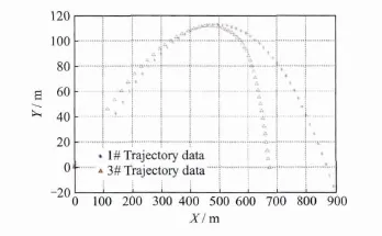
Fig.10 Trajectory curve
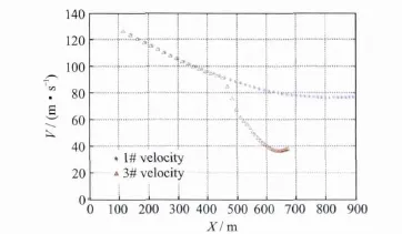
Fig.11 Velocity curve
6 Conclusions
(1)An available correction method is put forward for whole ballistic trajectory,and its feasibility is proved by the experiment.
(2)Software and hardware design of the correction system is introduced;furthermore,the feasibility and advancement of the control system scheme are validated through testing,indicating that the whole system meets the requirements of the system.
(3)The results of the experiments shows incontestably that the correction system is feasible and reliable,which provides a new idea for ODTCP.
[1] Zhang Minquan,Liu Dongfang.A summary for trajectory correction projectiles[J].Acta Armamentarii,2010,31(2):127-130.(in Chinese)
[2] Zhen Bing.The annual report of the world's weapon development[M].Beijing:The 202 Research Institute of Norinco Group,2009-2012.(in Chinese)
[3] Wang Zhongyuan,Shi Jinguang.Aerodynamic structure and correctional ability for one dimensional trajectory correction projectile[J].Journal of Nanjing University of Science and Technology:Natural Science,2008,32(3):332-336.(in Chinese)
[4] Hu Ronglin,Li Xingguo.Research on deciding the deployment time of damper for range correction projectiles[J].Journal of China Ordnance,2008,29(2):235-239.(in Chinese)
[5] Wang Zhongyuan,Shi Jinguang.Control method for trajectory correction [J].Journal of Ballistics,2011,23(2):19-21.(in Chinese)
[6] Texas Instruments Co Ltd.TMS320F28335 digital signal controllers(DSCs)data manual[M].Texas,USA:Texas Instruments Incorporated Inc,2007.
猜你喜欢
档案天地(2022年3期)2022-04-15
岭南音乐(2022年6期)2022-02-04
数学大世界(2020年5期)2020-12-18
方圆(2020年8期)2020-05-25
学苑创造·A版(2020年11期)2020-01-07
中学生数理化·七年级数学人教版(2019年11期)2019-09-10
初中生世界·七年级(2019年6期)2019-08-17
初中生世界·七年级(2017年11期)2017-12-11
初中生世界·七年级(2016年9期)2016-10-09
初中生世界·九年级(2015年6期)2015-09-10
 Transactions of Nanjing University of Aeronautics and Astronautics2014年3期
- Transactions of Nanjing University of Aeronautics and Astronautics的其它文章
- Experiment on Adiabatic Film Cooling Effectiveness in Front Zone of Effusion Cooling Configuration*
- Analysis for Transm ission of Com posite Structure w ith Graphene Using Equivalent Circuit M odel*
- Panoram ic Imaging System Inspired by Insect Com pound Eyes*
- Geometric Covariance Modeling for Surface Variation of Compliant Parts Based on Hybrid Polynomial Approximation and Spectrum Analysis*
- Fast SSED-MoM/FEM Analysis for Electromagnetic Scattering of Large-Scale Periodic Dielectric Structures*
- Focus Reflective Shock Wave Interaction with Flame