
Cavity filling water control below aerator devices*
2014-06-01 12:30QIANShangtuo钱尚拓WUJianhua吴建华MAFei马飞CollegeofWaterConservancyandHydropowerEngineeringHohaiUniversityNanjing210098Chinamailqshttc163comXUJianrong徐建荣PENGYu彭育WANGZhen汪振HydraulicStructuresdesigndivisionHydrochinaHuadong
水动力学研究与进展 B辑 2014年3期
QIAN Shang-tuo (钱尚拓), WU Jian-hua (吴建华), MA Fei (马飞)College of Water Conservancy and Hydropower Engineering, Hohai University, Nanjing 210098, China,E-mail: qshttc@163.comXU Jian-rong (徐建荣), PENG Yu (彭育), WANG Zhen (汪振)Hydraulic Structures design division, Hydrochina Huadong Engineering Corporation, Hangzhou 310014, China
Cavity filling water control below aerator devices*
QIAN Shang-tuo (钱尚拓), WU Jian-hua (吴建华), MA Fei (马飞)
College of Water Conservancy and Hydropower Engineering, Hohai University, Nanjing 210098, China,
E-mail: qshttc@163.com
XU Jian-rong (徐建荣), PENG Yu (彭育), WANG Zhen (汪振)
Hydraulic Structures design division, Hydrochina Huadong Engineering Corporation, Hangzhou 310014, China
(Received February 20, 2014, Revised May 30, 2014)
With the rapid development of high dam projects within China, the dragon-drop-tail spillway tunnel is introduced and widely used. In view of the high water head and the large flow velocity on the dragon-drop-tail section, aerator devices are usually placed for the cavitation damage control. For the device placed in its initial position, it is a serious concern to design a suitable flow regime of the cavity and to control the cavity filling water due to the large flow depth and the low Froude number through this aerator. In this study, the relationships between the geometries of the aerator device and the jet impact angle of the lower trajectory of the flow are theoretically analyzed with/without a local slope. Nine test cases with different geometries are designed, the effectiveness of the filling water control is experimentally investigated under different operation conditions, and two criteria of the local slope design are proposed. It is concluded that the cavity flow regime and the filling water can be improved if a small impact angle and some suitable geometries of the local slope are designed.
low Froude number, dragon-drop-tail spillway tunnel, filling water, local slope
Introduction
The dragon-drop-tail spillway tunnel consists of a short pressure inlet, a long mild-slope section, a steep slope section (named as the dragon-drop-tail section) and an outlet with energy dissipation effect. Comparing with the traditional dragon-raise-head section, it enjoys the advantages of small working head and pressure on the intake gate and most of the tunnel region[1], thus, it becomes a preferred choice of the spillway tunnel arrangement for the high dam projects like Baihetan and Jinping in recent years. Because of the high water head concentrating on the dragon-droptail section and the resulting large velocity of the flow in this section, it is necessary to place aerator devices for this kind of tunnels[2-4].
For the device placed in the initial position of thedragon-drop-tail section, however, the cavity filling water easily appears due to the low flow Froude number. The cavity and then the ventilation shaft may be drown out and the aerator device will lose its effect and even becomes a cavitation generator if there is enough filling water. Therefore, it is important to investigate the geometry of the aerator device for a suitable cavity regime and an effective filling water control under the conditions of the low flow Froude number.
In order to control the filling water inside a cavity, some new types of aerator devices are considered, like the dent-form ramp[5], the U-shaped ramp[6]and the V-shaped ramp[7], through which the flow is divided into several pieces impinging different sections of the bottom downstream and pushing the filling water into the mainstream[8]. These measures are adopted for the improvement of their ramps. Furthermore, others focus their attention on the bottom downstream of the aerator devices such as increasing a local slope downstream of the aerator in order to decrease the impact angle of the jet flow to the bottom. With regard to the local slope form, better effects on the filling water control are shown for a mild, even a flat bottom slope[9].
In fact, the occurrence of the filling water is affected by many factors, to which should be paid a careful attention, according to the performance of the flow. For the aerator on the bottom of the different release structures, different hydraulic characteristics are shown. For example,Fr(H) of the flow decreases through the aerator near the inlet of a spillway,Fr(H) increases first and then decreases when the aerator is placed downstream of this spillway, andFr(H) keeps to increase for a discharge tunnel[10], where =o/FrV(gh)2is the flow Froude number through the aerator,oVoandhoare the velocity and the flow depth, respectively,g=9.81m/s3is the gravitational acceleration, andHis the working head of the release structure.
Besides, for the aerator with a local slope form, the operation conditions of the release structure should be considered and the impact points of the upper and lower jet trajectories through the aerator to the bottom move forward whenHincreases. Therefore, the position and the length of the local slope section should be reasonably designed to meet the needs of those operations so that the impact points of the upper and lower jet trajectories could fall on the bottom of the local slope section.
In this paper, the aerator device in the initial position of the dragon-drop-tail section of the spillway tunnel for the Baihetan hydropower project is taken as the research object, and on the basis of the theoretical analysis of the aerator form effect on the filling water, the geometries of the aerator, especially the position and the length of the local slope section are experimentally investigated for the filling water control.
1. Theoretical consideration
It is well-known that the characteristics of the cavity and the filling water below an aerator are related to the impact angle of the lower trajectory of the flow to the bottom, and the larger the impact angle is, the more adverse the filling water and the cavity regime are[11-13].
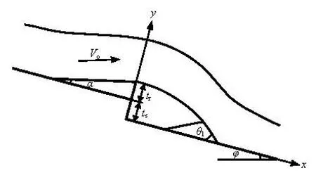
Fig.1 Sketch of traditional aerator device
Figure 1 shows the sketch of a traditional aerator device, in whichαis the ramp angle,tris the ramp height,tsis the offset height andφis the bottom slope to the horizontal plane. The velocity of the approach flow isVo, and, therefore, the velocity components alongx-axis andy-axis directions at the edge of the ramp areVox=VocosαandVoy=Vosinα, respectively.
The jet jumps away from the aerator with the accelerations alongx-axis andy-axis directions asgsinφand -gcosφ, respectively. Supposing that the jet is a rigid body, the timeT1leaving the aerator to impact the bottom downstream can be computed from the following path equation, based on the theory of free projectile
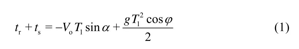
According to Eq.(1),T1can be solved as

The velocity componentsVtx1andVty1alongx-axis andy-axis directions at the impact point are expressed as:

respectively. Therefore, the jet impact angle 1θfor the traditional aerator device is expressed as

Figure 2 is the sketch of the aerator device with a local slope form downstream and the computation of the impact angle. The local slope form is placed in the impact zone of the jet to insure that the jet always falls within its scope. In order to permit the arrangement of the slope as steep as possible, a flat platform is set upto connect the local slope form with the bottom below the aerator.βis the angle of the local slope to the bottom,L1andL2are the lengths of the flat platform and the local slope section, respectively.

Fig.2 Sketch of aerator device with local slope form (a) and computation of impact angle (b)
It is assumed that the entire jet falls within the local slope section. Thus, the velocity at the edge of the ramp is the same as that in the traditional aerator device, in this way, the timeT2that the jet takes from leaving the aerator to the local slope section can be computed as

wherefis the thickness of the local slope form at the impact point of the lower jet trajectory. According to Eq.(7), we have

The velocity componentsVtx2andVty2alongx-axis andy-axis directions at the impact point are expressed as:

respectively. Thus, the jet impact angle2θfor a local slope form is expressed as:

Comparing Eq.(3) with Eq.(9), sinceB<A, obviously, we have

It indicates that the impact angle of the lower jet trajectory for the aerator device with a local slope is smaller than that for the traditional aerator device. Equation (12) shows that2θdecreases significantly whenβincreases, which theoretically indicates that arranging a local slope form below an aerator is effective in decreasing the impact angle and for the filling water control.
2. Experimental setup and methodology
2.1Experimental setup
The experiments were conducted in the Highspeed Flow Laboratory of Hohai University (Nanjing, China). Figure 3 shows the experimental setup and the physical model, which consists of a pump, an approach conduit, a large feeding basin, a model of the dragon-drop-tail spillway tunnel with aerator devices and a flow return system. The physical model, made of perspex, is designed at a scale of 1/40 for the spillway tunnel for the Baihetan hydropower project, based on the Froude similarity criterion.
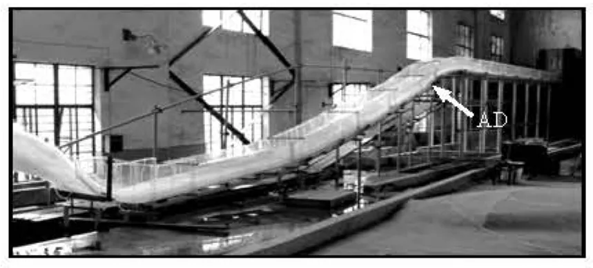
Fig.3 Experimental setup and aerator device (AD) studied
The spillway tunnel for the Baihetan hydropower project is 2 170.00 m long, 15.00 m wide and with 180.00 m drop as a prototype. The bottom slope of the dragon-drop-tail section is 1:4.0, connected to the long mild-slope section with a smoothed curve. The aeratordevice (AD) in this paper is placed in the initial position of the dragon-drop-tail section (shown in Fig.3) as the first aerator device of this spillway tunnel. The horizontal and vertical distances from the aerator to the initial position of the dragon-drop-tail section are 78.87 m and 12.30 m, respectively.

Table 1 Experimental cases and parameters of the aerator and the local slope forms
2.2Experimental methodology
Table 1 lists the experimental cases and the geometric parameters of the aerator and the local slope forms. These cases are named as M1 through M9 and designed to investigate the influences of the impact angle of the lower jet trajectory as well as the position and the length of the local slope form on the cavity and the filling water. Here M1 is the case of the traditional aerator without a local slope form downstream, and the other cases can be divided into three groups to investigate the effects of the angleβ(M2-M5), the lengthL2(M6-M8)and the lengthL1(M9), respectively.
The hydraulic characteristics of the aerator are investigated under different conditions. There are 3 operation heads, i.e., the model heads,HM=0.375 m, 0.875 m and 1.375 m, corresponding toHP=15.0 m, 35.0 m and 55.0 m, in the prototype. Thus, the approach Froude numbers are 4.54, 3.85 and 3.61, respectively, for the heads mentioned above. This means thatFrdecreases when the head of the reservoir increases, especially,Fr=3.61 is very low under the operation condition of the normal water level, i.e.,Hp=55.0 m. The parameters of the jet length (Lj), the filling water length (Lf) and the net cavity length (Ln) in Fig.2(a) are measured by a steel ruler. The impact angle of the lower jet trajectory is defined as tanθ2=tan-1(Δy/ Δx) with Δx=0.10 m in the model and Δyas the distance from the local slope bottom to the tangent line of the jet impact point (see Fig.2(b)).
3. Results and discussions
3.1Influence of the jet impact angle
The construction of the local slope form is controlled by three parameters: the angleβ, the initial positionL1(corresponding to the length of the flat platform) and the lengthL2. According to the theoretical consideration, the impact angle of the lower jet trajectory2θis mainly influenced byβand the hydraulic parameters of the approach flow, if the construction of the aerator is fixed.

Table 2 Jet impact angle2θ(o)
Table 2 gives the experimental results of the jet impact angles for the cases listed in Table 1, whereFr=3.61, corresponds to the normal water level of the reservoir, and it could be noticed that this aerator for the project works with the low Froude number.
For cases M1-M5, obviously, the impact angle 2θdecreases as eitherFrorβincreases for eachtest group. Comparing the experimental flow regimes, it is shown that, the small2θhelps to decrease and control the filling water inside the cavity. Comparing the traditional aerator device (M1), it can be seen that those with the local slope forms (M2-M5) perform better in controlling the filling water.
Meanwhile, it is noticed that, the increase of the angleβis not directly equal to the decrease of the impact angleθ2. Whenβ=12.00o, the decrease ofθ2is about 6.26o-3.64oforFr=3.61-5.45.
Figure 4 shows the variation ofLj/hoagainstFrfor M1-M5, wherehois the flow depth through the aerator. It indicates clearly that the jet length of the low trajectoryLj/hoincreases asFrincreases, and they have an approximate linear relationship. Considering thatLj/hois mainly dominated by the geometries of the ramp and the condition of the approach flow, each case would be similar, andLj/hoslightly decreases with the increase ofβdue to the increase off.

Fig.4 Variation ofLj/hoagainstFrfor M1-M5

Fig.5 Variation ofLf/hoagainstθ2for M1-M5
Figure 5 shows the variation ofLf/hoagainstθ2for M1-M5 under different operation conditions. Firstly, the length of the filling waterLf/hohas a linear relationship with the impact angle when the jet trajectory2θis less thano11.50. Secondly, when2θ≥11.50o, there is no clear trend, in fact, the filling water becomes severe comparing with the jet length of the low trajectory. Lastly, the condition of no filling water could be achieved when

This means that

That is to say, the filling water could be controlled ifθ2≤θ2c.

Fig.6 Variation ofLn/hoagainstFrfor M1-M5

Fig.7 Comparisons of cavity flow regimes withFr=3.61
Figure 6 is the variation ofLn/hoagainstFrfor M1-M5. The net cavity lengthLn/hoalso influencesthe performance of the air entrainment to the flow. It could be seen thatLn/hoincreases asFrincreases. Meanwhile, comparing cases M1 to M5, it is clearly seen that with the increase ofβ, the impact angle2θdecreases, and thenLn/hoincreases.
Figure 7 shows a comparison of the flow regimes through the aerator devices for M1 and M5 whenFr=3.61.
With respect to M1 without the local slope section, it could be seen that the filling water submerges the ventilation shaft and the net cavity is very small. While the local slope section is placed downstream of the aerator, the filling water is effectively controlled, such as in the case of M5.
3.2Influence of initial position and length
For the aerators with a mild slope and/or a low Froude number, the placement of the local slope forms downstream is a preferred choice for the cavity filling water control[9,10,14,15]. In fact, the effectiveness of this geometry is closely related to the operation conditions of the release structure. So in the designs of the aerator device and the local slope section, at least two factors should be considered, i.e., the initial position (L1) and the length (L2) of the local slope section.
Firstly, the length (Lj) of the low trajectory of the flow should be larger than the initial position (L1) to keep the flow falling on the local slope section.
Secondly, let the points A and B be the positions of the lower and upper trajectories of the flow at the bottom of the local slope section, we can have the distance from A to B alongx-axis direction denoted asL3(see Fig.2(a)). In any operation situation, the entire jet flow can fall within the local slope section whenL1+L2≥Lj+L3andLj>L1.

Fig.8 Variation ofLf/hoagainstFrfor M6-M9
Figure 8 shows the variation ofLf/hoagainstFrfor cases M6-M9. In the cases of M6-M8, we have the sameβandL1, i.e.,β=9.00oandL1= 0.225 m, butL2=0.375 m, 0.413 m and 0.450 m. We can see thatLf/hodecreases with the increases ofFr. Much more important is the fact thatLf/hosignificantly decreases when the length of the local slope section increases, which means that the jet flow falls wholly in the length ofL2with the increase of it.
However, the filling water will become severe if the impact point of the lower jet trajectory can not fall
on the local slope section, such as whenLf/hois equal to 3.22 for the case of M9 whereL1=0.300 m andFr=4.54. Therefore, it is important to properly adjust the lengthL1, or the initial position for the filling water control.

Fig.9 Comparisons of flow regimes whenFr=3.61
Figure 9 shows the flow regimes on the aerator devices atFr=3.61 for cases M6-M8. It could be seen that, the lengths of the filling water are similar for M6 and M7, while that for M8 is obviously short.
As stated above, the two criteria of the design of the aerator device with a local slope form placed could be proposed as

4. Conclusions
With respect to placing a local slope form downstream of an aerator device for the filling water control, the impact angle of the lower trajectory of the flow is theoretically analyzed, and compared with the case without this form.
The performance of the cavity filling water is experimentally investigated. The relationship between the filling water and the impact angle could be expressed by Eq.(14), and the filling water could be controlled if the impact angle is less thano8.56.
For the aerator devices with the low Froude number, it is a good choice to place a local slope section, but there are two criteria that need to be satisfied when this form is designed and they are expressed by Eqs.(16) and (17).
[1] GUO Jun, ZHANG Dong and LIU Zhi-ping et al. Achievements on hydraulic problems in large spillway tunnel with a high head and large discharge flow and its risk analysis[J].Journal of Hydraulic Engineering,2006, 37(10): 1193-1198(in Chinese).
[2] CHANSON H. Study of air entrainment and aeration devices[J].Journal of Hydraulic Research,1989, 27(3): 301-319.
[3] HAGER W. H., PFISTER M. Historical advance of chute aerators[C].33rd IAHR Congress.Vancouver, Canada, 2009, 5827-5834.
[4] PFISTER M. Chute aerators: Steep deflectors and cavity subpressure[J].Journal of Hydraulic Engineering, ASCE,2011, 137(10): 1208-1215.
[5] ZHI Shuan-xi, YAN Jin-yuan. Hydraulic characteristics of aerators with dent-form ramp[J].Journal of Hydraulic Engineering,1991, (2): 42-46(in Chinese).
[6] SUN Shuang-ke, YANG Jia-wei and LIU Hai-tao. Optimistic study on the layout of aeration facilities under mild gradient[J].Water Resources and Hydropower Engineering,2004, 35(11): 26-29(in Chinese).
[7] WANG Hai-yun, DAI Guang-qing and YANG Qing et al. Experimental study on V-type aerator for spillway tunnel with inlet raised[J].Journal of Hydraulic Engineering,2005, 36(11): 1371-1378(in Chinese).
[8] WU Jian-hua, MA Fei and DAI Hui-chao. Influence of filling water on air concentration[J].Journal of Hydrodynamics,2011, 23(5): 601-606.
[9] SU Pei-lan, LIAO Hua-sheng and QIU Yue et al. Experimental study on a new type of aerator in spillway with low Froude number and mild slope flow[J].Journal of Hydrodynamics,2009, 21(3): 415-422.
[10] WU Jian-hua, MA Fei. Cavity flow regime for spillway aerators[J].Science China Technological Sciences,2013, 56(4): 818-823.
[11] PFISTER M., HAGER W. H. Chute aerators. I: Air transport characteristics[J].Journal of Hydraulic Engineering, ASCE,2010, 136(6): 352-359.
[12] PFISTER M., HAGER W. H. Numerical computation of slit-type supercritical flows[J].Journal of Hydraulic Engineering, ASCE,2010, 136(6): 360-367.
[13] PFISTER M. Jet impact angle on chute downstream of aerator[C].4rd IAHR International Symposium on Hydraulic Structures.Porto, Portugal, 2012, 1-8.
[14] QI Li-jian, LIAO Hua-sheng and LI Gui-ji et al. Numerical simulation of backwater downstream of aerators in spillway with low Froude number flow[J].Journal of Hydraulic Engineering,2007, 38(7): 819-825(in Chinese).
[15] SU Pei-lan, LIAO Hua-sheng and LI Lian-xia et al. Application of aerator with a trapezoidal-shaped slot on a steep slope to the spillway tunnel of Pubugou hydropower project[J].Journal of Hydroelectric Engineering,2010, 29(2): 168-175(in Chinese).
10.1016/S1001-6058(14)60048-2
* Project supported by the National Natural Science Foundation of China (Grant No. 51179114).
Biography: QIAN Shang-tuo (1988-), Male, Ph. D. Candidate
WU Jian-hua,
E-mail: jhwu@hhu.edu.cn
猜你喜欢
Chinese Physics B(2022年9期)2022-09-24
故事作文·低年级(2022年1期)2022-02-03
故事作文·低年级(2018年11期)2018-11-19
水动力学研究与进展 B辑(2018年5期)2018-10-27
故事作文·低年级(2018年9期)2018-09-17
故事作文·低年级(2018年6期)2018-07-04
水动力学研究与进展 B辑(2018年2期)2018-05-14
水动力学研究与进展 B辑(2017年4期)2017-09-15
读写算·小学低年级(2017年4期)2017-04-15
作文周刊·小学一年级版(2016年29期)2017-03-02

- 水动力学研究与进展 B辑的其它文章
- Numerical simulation of landslide-generated impulse wave*
- A random walk simulation of scalar mixing in flows through submerged vegetations*
- Scaling of maximum probability density function of velocity increments in turbulent Rayleigh-Bénard convection*
- Dispersion in oscillatory electro-osmotic flow through a parallel-plate channel with kinetic sorptive exchange at walls*
- Evaluation of the use of surrogateLaminaria digitatain eco-hydraulic laboratory experiments*
- A numerical study on dispersion of particles from the surface of a circular cylinder placed in a gas flow using discrete vortex method*