
Electro-mechanical power coup ling system for PHEV with high price-performance ratio*
2014-06-09 14:44FedermannFlorianYueCHENGXinLIBoZHANGJiajiaXIEYangYU
机床与液压 2014年3期
Federmann Florian,Yue CHENG†,2,Xin LI,Bo ZHANG,Jia-jia XIE,Yang YU
1Landshut University of Applied Sciences,Landshut D-84036,Germany;2Key Laboratory of Advanced Manufacturing Technology for Automobile Parts,Ministry of Education,Chongqing University of Technology,Chongqing 400054,China;3School of Vehicle Engineering,Chongqing University of Technology,Chongqing 400054,China
Electro-mechanical power coup ling system for PHEV with high price-performance ratio*
Federmann Florian1,Yue CHENG†1,2,Xin LI3,Bo ZHANG3,Jia-jia XIE3,Yang YU3
1Landshut University of Applied Sciences,Landshut D-84036,Germany;2Key Laboratory of Advanced Manufacturing Technology for Automobile Parts,Ministry of Education,Chongqing University of Technology,Chongqing 400054,China;3School of Vehicle Engineering,Chongqing University of Technology,Chongqing 400054,China
The price-performance ratio of PHEV determines its market penetration.Besides engine and battery,the power coup ling system including traction motor and automatic transmission is a key influence factor of system performance and costs.This article introduces an electro-mechanical power coup ling system for PHEV with high price-performance ratio,which integrates an electro-mechanical CVT and a flat traction motor.As an example,a PHEV system is configured to conform the vehicle dynamic specifications.
PHEV,Coupling system,Dynamic specification,CVT
1.Introduction
Fuel saving ratio of Plug-in Hybrid Electric Vehicle(PHEV)amounts to 40%,although its advantages over comprehensive energy consumption,CO2emissions and other indicators remain open to question,but in terms of factors such as city air pollution,battery recycling and industrial structure transformation,great importance has been attached to it by the government and industry.At present,the price of PHEV is the biggest barrier affecting the market acceptance[1].
As core parts of PHEV,electro-mechanical power coupling system including the ISG motor,automatic transmission and its controller has become another bottleneck in addition to the power battery system and hybrid control system(HCU)for the market expansion of PHEV.The difficulty lies in:
1)Price-performance ratio,one-time purchase cost of PHEV vehicle and comparison between increasing operation and maintenance costs and decreasing fuel costs.All the factors will determinate the appeal for customers.The price and maintenance costs of electro-mechanical power coupling system account for a large proportion in that.
2)Axial size.PHEV will be widely used in small family cars A with front engined front drive in China,internal combustion engine,ISG motor,and axial size of powertrain consisting of automatic transmission are the bottlenecks for its engineering approaches;
3)Reliability and maintainability of the system. This article introduces an electro-mechanical power coupling system for PHEV with high price-performance ratio,which integrates an electro-mechanical CVT and also dynamic design for its application in one model is carried out.
2.Electro-mechanical CVT
With new transmission structure and technology,automatic transmission,being as the electro-mechanical power coupling system for PHEV,should meet the following requirements:
1)In order to achieve working conditions of the pure electric,hybrid,charging and energy recovery,two controllable power interruption between engine and drive motor,drive motor and wheel can be realized on power coupling system inside the powertrain.
2)To support the vehicle solely on electric,especially at the initial stage of the driving.
3)Lower cost and higher transmission efficiency.
4)Smaller axial size.
Among various kinds of advanced automatic transmission,CVT transmission has the following advantages:
1)Power shift/speed control without coordination of torque/speed on power supply.
2)Simple shift operation,only axial movement of cone plate.
3)Smaller axial size.
In the application of PHEV,the conventional CVT of electro-hydraulic control has the following disadvantages:
1)Energy consumption.The hydraulic system with CVT of electro-hydraulic control gets low efficiency and high energy loss.Research shows that if electro-hydraulic control system can be replaced by electro-mechanical,the system efficiency will rise by 10%~17%.
2)Reliability.Reliability and stability of hydraulic system will decrease for the following factors:characteristics of hydraulic oil viscosity-temperature,impurity and pollutant in the hydraulic oil and aging process of hydraulic oil.
3)High cost.Fluid control element and the processing of related oil structure on the shell will result in the rising cost of CVT.
4)Hydraulic of hydraulic system is difficult to set under the pure electric working condition of lower speed.
As improvement for existing CVT of electro-hydraulic control,motor actuators is adopted as speed control system in electro-mechanical CVT(EMCVT),and hydraulic pressure system is replaced by mechanical pressurization system.Performance tests on EM-CVT prototype from China's motor vehicle quality supervision and inspection center shows the average efficiency of the EM-CVT exceeds more than 90%with its peak efficiency of94%,and is suitable for the working condition of pure electric drive[2-5].
EM-CVT system is divided into several parts:continuously variable transmission unit,speed control unit,speed reducer and differential unit,gear DNR(shift)and clutch.
Structure of EM-CVT system combines AMT and CVT,among which traditional 11 degrees cone plate is applied in core transmission of CVT including cone plate and steel belt.In this way,mature design theory of CVT can be applied in its basic transmission design[6-13].
In order to reduce costs and energy consumption,mature products and technologies are applied in clutch and shifting unit,which can also ensure sound working conditions of CVT in pure electric mode.
3.Structure of electro-mechanical coupling system and the PHEV steady driving mode
In order to achieve cost-effective system,the author chooses the following design(see Figure 1 and Figure 2)[14-18]:
1)Electrical-mechanical control CVT(EMCVT)being as the coupling device of system.
2)Drive motor adopts light-weight(flat)permanent magnet synchronous motor(ISG motor),the structural design of which is collaborative with EM-CVT.
3)Parallel hybrid system is adopted,in which dry automatic clutch is applied for power interruption between motor and engine(P1),and power interruption between motor and wheel(P2)is achieved through synchronizer that shifts into neutral.
4)Engine-matched enhanced start motor.According to the system requirements of NVH,the engine is started through speed ratio between drive motor and CVT or through motor initiation.After speed of the engine to amounts to the current motor speed,combination of clutch P1 and engine is achieved.

Figure 1.Basic structure of system
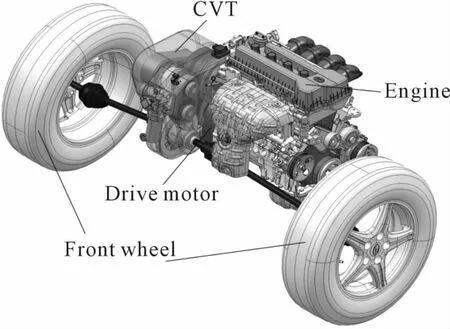
Figure 2.Front cabin layout design of powertrain
By adjusting engine compartment,engine and the layout and size of the motor on small family car from home and abroad,the best axial size should be 230~250 mm,which will not affect the original transmission.
Here attached various steady driving mode of PHEV in structure design for electro-mechanical coupling system(see Table 1):
1)Engine drive mode.When SOC of power battery is less than the minimum limit set,the vehicle can be driven by engine solely.
2)Motor drive mode(solely depending on electricity).When SOC of power battery is within normal range of setting and the output power of motor can meet the demand of PHEV power for driving intention,the vehicle can be driven by motor solely.
3)Engine/motor hybrid mode.For certain driving intention,the output power of motor can meet the demand of PHEV,i.e.,under the working condition,the power vehicle demands is high and the SOC of battery is within the normal range of setting,then the vehicle can be driven by both engine and motor with superposition of output torque.
4)Run-charging mode.When SOC of power battery amounts to charging initiated limit set by energy management system and the power engine provides exceeds vehicle’s demand in current working condition,the surplus power of the engine can be used for power battery charging.
5)Parking-charging mode.When SOC of power battery amounts to charging initiated limit set by energy management system,driver will be prompted to start engine to charge the battery under the condition of stop.
6)Regenerative braking mode.When SOC of power battery is less than a certain value,the vehicle will shift into regenerative braking mode under conditions of slow or slight brake.The system will maximize the energy recycling by comprehensively coordinating control system of CVT,motor and battery management system(BMS)[13].Requirements of the current condition and NVH of vehicles will determine brake of engine;When the brake force demand of vehicle is large or anti-lock braking system(ABS)is in need,brake will work alone and regenerative braking stop for safety reasons[14].
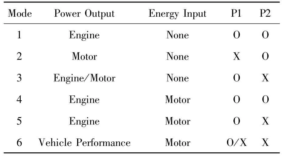
Table 1.Various steady driving mode of PHEV(O:combination,X:separation)
Shifting of above mentioned model is also called transient model,which is not related to system structure.Control strategy will be discussed in other article[19-20].
4.Dynamic design of vehicle
The design goal of electro-mechanical power coupling system mentioned in this article is to reduce fuel consumption by more than 40%(according to calculation and test of national standard GBT19753—2005)with sound vehicle power performance for small-family cars,so as to determine optimal matching of engine and drive motor parameters.The requirements for vehicle technical parameters are shown in Table 2.

Table 2.Performance requirements and parameters of the vehicle
4.1.Determination of drive motor and engine
To meet the maximum cruising speed of 100 km/h under pure electric mode,dynamic simulation calculation is made with 90%of the total efficiency for transmission system.Based on the results(see Figure 3),rated power of the drive motor is fixed as 20 kW.Its speed-torque characteristic curve is shown in Figure 4.
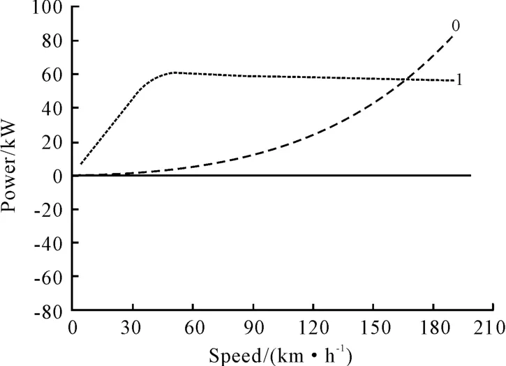
Figure 3.Simulation calculation results of motor rated power and engine power

Figure 4.Drive motor speed-torque characteristic curve
According to maximum speed requirements under working conditions of engine/motor hybrid drive,considering the efficiency of motor and transmission system,engine speed-torque characteristics which match the motor should meet the demand shown in Figure 5.At present,the 1.2 L naturally aspirated engine or a 0.8-liter turbocharged engine can meet the demand.
4.2.Determination of variable speed ratio for transmission
As per the requirements of highest gradability for PHEV,speed-torque characteristic curve for joint work of engine and motor can be made under hybrid mode,ie,the input characteristic curve of transmission(see Figure 6).According to the curve,maximum variable speed ratio for transmission should amount to 15 for the requirements of gradability.According to the structure parameter of electro-mechanical CVT(EM-CVT),variable speed ratio should be fixed from 2.75 to 16.6.

Figure 5.Engine characters curve that match the PHEV motor

Figure 6.Input characteristic curve of transmission on hybrid mode
4.3.Verification of acceleration performance
In hybrid mode,acceleration curve of PHEV with above dynamical system is as follows:
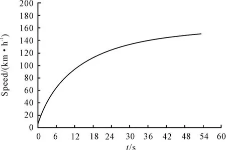
Figure 7.Acceleration curve of PHEV
From the above figure,0~100 km/h acceleration time of PHEV is 13.8 s,which meets the requirements of accelerating time of 14.3 s[21].
5.Architecture of transmission control unit(TCU)in coup ling device of electro-mechanical coupling system
In order to increase the versatility and reliability of TCU in coupling device of electro-mechanical coupling system and reduce costs,frame as shown in Figure 8 is adopted[22]:
1)Controlling motor drive module of EM-CVT is integrated on the motor,the communication of which with TCU is achieved through CAN field-bus.
2)Electronic shift lever adopts security mechanism of double bus(CAN+LIN).
3)Other major subsystems adopt CAN communication.
4)HCU functions are integrated in TCU hardware.

Figure 8.TCU frame
To meet the ISO26262 requirements for safety of communication system function,independent CAN and LIN bus is set up to improve the safety of system function,especially for shift lever controller.
Since diagnostic function is achieved through LIN bus,in order to read and eliminate the fault code during diagnosis,LIN bus controller adopted in communication should be set as duplex mode.
Shift lever controller not only calculates gear position,but also integrates other man-machine interface function,such as electronic parking(EPB,E-lectrical Park Brake),ramp start auxiliary and so on.In order to meet future demand,such as autopilot(current market demand:automatic parking,adaptive cruise(ACC),etc.)and other requirements of mode switch on PHEV.Shift lever controller need to acquire other driving request in addition to gear position signals,therefore the communication pattern of CAN should be also set as duplex mode.
6.Conclusion
For the increasing demand of energy saving,intelligent and low cost in auto industry,electric actuator is one of the development trends.Electric control of automatic transmission is accord with the requirement for the market development of PHEV.
Electro-mechanical power coupling system for PHEV with high price-performance ratio integrates drive motor and EM-CVT,which gets low cost and high efficiency and is quite suitable for various working condition and mode switch of PHEV.Its smaller axial size is especially suitable for vehicle of front engined and front drive.
The coupling system can satisfy the power demand of PHEV at most working conditions.With total power of 8~10 kWh for power battery pack,this system can support a travel range of 50 km under pure electric condition.Above all,electro-mechanical power coupling system with high price-performance ratio can meet the demand of PHEV in terms of power,fuel saving and economic driving.
[1] ENGLISCH A,FAUST H,HOMM M,et al.Potentials for the Development of Continuously Variable Transmissions[J].ATZ worldwide,2003,7-8:11-14.
[2] ENGLISCH A,FAUST H,HOMM M,et al.Development of High Performance CVT Components[J].VDIBerichte,2004,1827:649-668.
[3] WAGNER G,REMMLINGER U,FISCHERM.CFT30-A Chain Driven CVT for FWD 6 Cylinder Application[J].SAE,2004-01-0648.
[4] LUTZ N,HEINZ U,PFEIFFER F.Noise Reduction of Chain-CVTs using Optimisation Techniques[J].SAE,2006-01-1309.
[5] INDLEKOFER N,WAGNER U,FIDLIN A,et al.Latest Results in the CVT Development[C].7th Luk Symposium,2002:63-72.
[6] WANG Yixing,ZHENG Zhifeng,ZHANG Guangyi. Theory Analysis of Hy-Vo Chain Variable Pitch[J]. Journal of Jilin University of Technology,1983,(1):42 -46.
[7] MENG Fanzhong,LI Qihai,FENG Zengming.Meshing Analysis and Design Method of New Hy-Vo Silent Chain and Sprocket[J].Chinese Journal of Mechanical Engineering,2007,43(1):116-119.
[8] YAN Jingping.The Mechanism Analysis for Uniform Motion of Chain with Varying Pitch[J].Nanjing Institute of Technology,1988,6(2):123-131.
[9] LUO Shun-zhi,CHENG Yue,LI Xin.Control of Transmission Ratio for Machinery and Electronic Control Metal Belt and Its Simulation[J].Journal of Chongqing University of Technology:Natural Science,2011,8:14 -20.
[10]CHENG Naishi.Metal V-belt CVT of Auto:Theory and Design of CVT[M].China Machine Press,2008.
[11]YE Ming,CHENG Yue.Study on Dynamic Control of Continuously Variable Transmission Driven by DC Motor[J].Mechanical Transmission,2011,2:9-12.
[12]YANG Xinhua,JIANG Qiang,CHENG Yue,et al.A Simulation Study on the Speed Ratio Variation Characteristics of Motor Controlled Metal V-belt CVT[J].Automotive Engineering,2012(4):320-322.
[13]CHENG Yue,WU Junyi,LIXin.An Improved PID Algorithm for the Speed Ratio Control and Simulation of E-lectro-mechanical Continuously Variable Transmission[J].Hydromechatronics Engineering.2013,41(12):6 -13.
[14]NOWATSCHIN K,FLEISCHMANN H P,GLEICH T,et al.Multitronic-The New Automatic Transmission from AUDI[J].ATZ worldwide,2000,9:29-31.
[15]NOWATSCHIN K,FLEISCHMANN H P,FRANZEN P,et al.Multitronic-The New Generation of Automatic Transmission[J].VDI-Berichte,2000,1565:195 -213.
[16]ROLF P,LINO G,CHRISO.A control-oriented CVT model with nonzero beltmass[J].Journal of Dynamic Systems,Measurement,and Control,2002,124:481-484.
[17]Howard C.Performance of CVT Transmissions[J]. SAE,1986.
[18]Micklem D,Longmore K,Burrows R.Belt torque loss in a steel pushing V-belt continuously variable transmission[J].Journal of Automobile Engineering,1994,208(2):91-97.
[19]YEMing,CHENGYue,SHUHong.Mode Shifting Control of Plug-in Hybrid Electric System Equipped with Mechanic-electric CVT[J].Chinese Journal of Mechanical Engineering,2014(5):585-589.
[20]LIXin,ZHANG Shi-jing,XU Nan-shao.Characteristic analysis and simulation of a new-type continuously variable transmission carried in EV[J].Journal of Chongqing University of Posts and Telecommunications:Natural Science Edition,2014(2):109-113.
[21]LIU Xue-mei,HUANGWei,ZHOU Yun-shan.A Study of Parameter Design of Power and Transm ission System for Plug-in Hybrid Electric Vehicle[J].Computer Simulation,2009,10:302-306.
[22]WU Weili,LAN Fengchong,CHEN Jiqing,et al.Costbenefit Analysis of Parameter Design of Powertrain for Plug-in Hybrid Electric Vehicle[J].Mechanical Science and Technology for Aerospace Engineering:2013,32(3):383-387.
The Fluid Control Engineering Institute of Kunming University of Science and Technology was set up in 1996.The researches of institute concentrate on electro-hydraulic(pneumatic)servo/proportional control and hydromechatronics.The Institute is committed to research and development of electro-hydraulic control of high-end technical equipment in ferrous metallurgy refining production.Projects undertaken and participated by the copper electrolysis anode preparation equipment,lead residual anode washing production lines as a host device received the second prize of the National Science and Technology Progress Award in 2009,the first prize and the third prize of the Yunnan Provincial Science and Technology Progress Award and many other awards.The institute has developed and put into operation more than a dozen sets of large equipment,and more than 20 national patents,which have been transformed into related products,providing professional package services of technology and equipment for non-ferrous metallurgical enterprises Address:College of Mechanical and Electrical Engineering,Chenggong Campus of Kunming University,727#,Jingming South Road,Chenggong University City,Kunming City,Yunnan Province
Zip Code:650500
Contact:Sun Chungeng,13608850651/Liu Sen,13888749366
Introduction of the Fluid Control Engineering Institute of Kunming University of Science and Technology

Fig.1 The copper electrolysis anode preparation equipment

Fig.2 The lead electrolysis washing and rods drawing off equipment

Fig.3 Electro-hydraulic operation special crane

Fig.4 The lead residual anode washing equipment
10.3969/j.issn.1001-3881.2014.18.001
2014-05-22
*Project supported by National Natural Science Fund Program“Research of Control for Electro-mechanical CVT PHEV System”(Fund Number:51275549),Natural Science Fund Program of Chongqing Science and Technology Committee(Fund Number:cstc2012jjA60003),and Chongqing Scientific Research Program(Fund Number:cstc2012gg-yyjsB60002)
†Yue CHENG,Professor.E-mail:chengyue0049@gmail.com
- 机床与液压的其它文章
- Research on the inference of CNC machine fault based on Bayes and FTA
- Design of 20 t forging manipulator clam p rotation hydraulic control system*
- Particle removal by an oscillating bubble in the pipe*
- Design and application of attitude measuring device for DC power output filter circuit
- Simulation of automobile ESP system based on fuzzy control*
- Research on multi-axial multi-excitations road simulation test method for AMT actuator*