
Modal and harmonic response analysis of spindle system on CNC worm wheel gear grinding machine
2014-07-31 20:22HonggangMUJinquanZHANGXianggenXUYeCHEN
机床与液压 2014年2期
Hong-gang MU, Jin-quan ZHANG, Xiang-gen XU, Ye CHEN
1Nanjing University of Science and Technology, Nanjing 210094, China;2Jiangnan Mine Electric Machinery, Zhenjiang 212009, China
Modal and harmonic response analysis of spindle system on CNC worm wheel gear grinding machine
Hong-gang MU†1,2, Jin-quan ZHANG2, Xiang-gen XU2, Ye CHEN2
1NanjingUniversityofScienceandTechnology,Nanjing210094,China;2JiangnanMineElectricMachinery,Zhenjiang212009,China
Based on the characteristics of simple harmonic vibration of CNC worm wheel gear grinding machine in the process of grinding, a three-dimensional finite element model of the spindle system was established. Modal analysis and harmonic response analysis were carried out through finite element software ANSYS. The natural frequencies and modes of the spindle system were obtained by the modal analysis. The effect of supporting stiffness of ball bearings to the natural frequencies was evaluated. The deformation-frequency response curve was obtained by analyzing the harmonic response of the spindle system. Lastly, the resonance vibration was verified by the critical speed. The results showed that the increasing supporting stiffness of the ball bearing was conducive to the improvement of the spindle system’s natural frequencies. When the frequency of grinding exciting force was in the vicinity of 600 Hz, deformation-frequency response curve showed a peak response to 6.56 μm. In order to avoid resonance vibration, the operating speed of the spindle system should avoid the first-order critical speed.
Spindle system, Modal analysis, Harmonic response analysis, Resonance vibration, Critical speed
1.Introduction
Modern machinery manufacturing industry is developing rapidly towards direction of high-speed, high-efficiency and high-precision. The continuous grinding method is employed by five axis Y7232CNC worm wheel gear grinding machine with characteristics of high speed and efficiency. The grinding wheel spindle is driven by built-in servo direct drive motor. The maximum speed of wheel spindle reaches 7 000 r/min. The maximum grinding speed achieves 90 m/s, and the highest grinding precision of gears reaches IT3. As a core component of high-end CNC grinding machine, the spindle system has the characteristics of simple harmonic vibration in grinding process because of its high speed. The dynamics of the spindle system directly affects the stability and reliability of the CNC grinding machine etc., and then affects the grinding precision of gears.
The dynamics of the spindle system and the machining accuracy of the grinding machine submit a direct relationship, so the research on the dynamics of spindle system has always become a hot topic. Luo Xiaoyingstudied dynamics of the spindle system in the spiral bevel gear grinding machine[1]. The research indicated that the different structure parameters had an impact on the natural frequencies of the spindle system. Yu Tianbiao considered the supporting stiffness of liquid hybrid bearing and rotating prestressing force produced in the process of high grinding, and the modal analysis of the spindle system was carried out on ultra-high-speed grinding machine[2]. The results showed that the supporting stiffness of the liquid hybrid bearing was dependent on the spindle speed. With the increase of the spindle speed, the natural frequencies of the spindle system were increased. Cai Ligang considered the radial stiffness of the spindle bearing, and the modal analysis of spindle was conducted[3]. It was shown that the simulation results were more accurate when the spindle was taken as the beam element model. Tian Jie studied the dynamics of the spindle on the magnetic suspension grinding machine[4]. The relationship between the supporting stiffness and the natural frequency was obtained. The vibration harmonic analysis of the spindle on the mineral oil separator was undertaken by Zhao Zhiguo. The amplitude-frequency characteristic curve and the maximum stress were obtained when the resonance vibration occurred[5].
Combined with previous studies on the dynamics of the spindle, the dynamics of the spindle system on Y7232CNC worm wheel gear grinding machine was studied by the author in this paper. The spindle system, mainly composing of electric spindle and wheel spindle, was the core component of the grinding machine. The natural frequencies, mode shapes, and resonance speed were obtained by finite element analysis, for the purpose of optimizing the structure of the spindle system, selecting a reasonable spindle speed and avoiding resonance vibration.
2.Theory of modal analysis and harmonic response analysis
For the multi-degree of freedom system, the kinetic equation can be described as

(1)
Where[M],[C] and[K] respectively represent the system mass, damping, and stiffness matrices.x(t) is the displacement vector, andF(t) is the external load.
The natural frequency is independent of the external load and the damping term is ignored when the modal analysis is made. Therefore, the dynamics equation of the multi-DOF system is as follows

(2)
Assuming the system submits simple harmonic motion, then

(3)
Whereφis the amplitude of the displacement vector,ωis the angular frequency of the simple harmonic motion, andθis the initial phase angle.
Substituting equation (3) into equation (2),
(4)
Since equation (4) are established at any time, equation (4) can be described as
(5)
If equation (5) has a nonzero solution, the following condition is met
(6)
The eigenvaluesωiare obtained by solving equation (6), namely the natural frequencies of the free vibration system. Substituting eigenvalues into equation (5), the modes corresponding to the natural frequencies can be obtained.
For harmonic response analysis, the general motion equations of system can be defined as

(7)
Where[M],[C] and [K] respectively represent the system mass, damping, and stiffness matrices.x(t) is the displacement vector, and {f(t)} is the harmonic load.
The external load and displacement vectors submit simple harmonic motion, assuming that the frequencies are the same and the phase angles are zero, in that case,
Substituting equation (8) and equation (9) into equation (7), then
(10)
In that way, the amplitude of the forced vibration can be obtained by solving the equation (10).
3.Finite element model of the spindle system
3.1.Spindle system model
The spindle system of Y7232CNC worm wheel gear grinding machine includes five parts: electric spindle, wheel spindle, centering sleeve, chuck, and worm grinding wheel. The various components of the spindle system are connected by bolts or interference fit, in which electric spindle and wheel spindle are connected by interference fit. Given the complexity of the actual spindle system, the appropriate and reasonable simplification are needed in modeling, such as ignoring the threaded holes, chamfers, undercuts and so on. In this paper, three-dimensional modeling software is used to model the spindle system, and then the three-dimensional model is imported ANSYS software to carry out modal analysis and harmonic response analysis. The three-dimensional finite element model of the spindle system is shown in Figure 1.

Figure 1. Three-dimensional and finite element model of the spindle system
3.2.Supporting way of spindle system
The spindle system is sustained by three pairs of angular contact ceramic ball bearings. As shown in Figure 1, the first pair of angular contact ball bearings are arranged in the position of Chuck. The second and the third pairs of angular contact ball bearings are respectively arranged on the front and the back of electric spindle. The angular contact ball bearings are used on the spindle system, which can not only withstand the bear radial load, but also the axial load. The axial load is smaller than the radial load, so it is not considered in this paper. The deformation of bearing is mainly caused by the radial load. Under the pressure of the radial load, the corresponding deformation of inner rings, outer rings, and rolling will occur, so it is needed to define a radial bearing stiffness of angular contact ball bearings. Figure 2 is the sketch of bearing-shaft fit. In Figure 2, the support of angular contact ball bearings is simplified, and the radial supporting stiffness of angular contact ball bearings is equivalent to the stiffness of the spring.
The radial stiffnesskron angular contact ceramic ball bearings can be defined as[6]
(11)
Where,Zrepresents the number of rolling;Dbis the rolling diameter of ball bearings;αis the contact angle of ball bearings;Fa0is the preload of ball bearing.
According to formula (11), the radial supporting stiffness of the three positions from left to right on the spindle system is given in Table 1 when different parameters are selected.
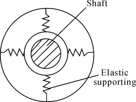
Figure 2. Sketch of bearing-shaft fit
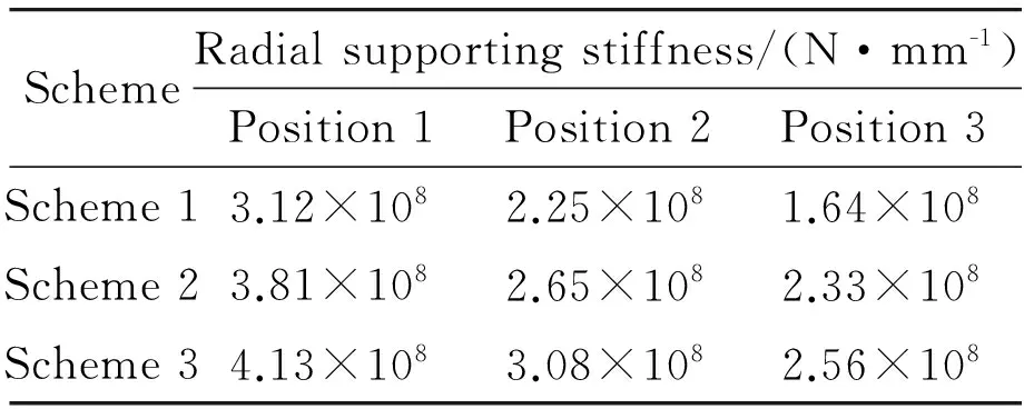
SchemeRadialsupportingstiffness/(N·mm-1)Position1Position2Position3Scheme13.12×1082.25×1081.64×108Scheme23.81×1082.65×1082.33×108Scheme34.13×1083.08×1082.56×108
4.Modal analysis of the spindle system
According to the radial supporting stiffness of ball bearing in Table 1, modal analysis of the spindle system is carried out in order to obtain the six-order natural frequencies and mode shapes. The first-order mode shape of the spindle system is the axial vibration of the wheel spindle, and the amplitude of wheel parts is maximum. The second-order and the third-order mode shapes of the spindle system are the bending vibration of the wheel spindle. The fourth-order mode shape is the axial vibration of the spindle system. The fifth and sixth-order mode shapes are the bending vibration of the electric spindle, and the middle of electric spindle has the maximum amplitude. In summary, it can be seen that the dominant modes of the spindle system are the axial vibration and the bending vibration. Due to space limitations, only the third-order mode shape of the spindle system is shown in Figure 3.
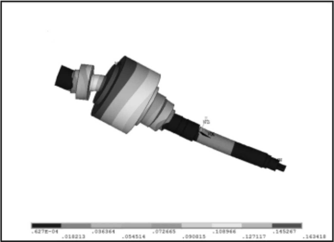
Figure 3. Third-order modal shape of spindle system
To study the effect of the supporting stiffness of ball bearing for natural frequencies, the three schemes are selected, and the modal natural frequencies are shown in Table 2. It can be seen, with the increase of the radial supporting stiffness, the natural frequencies of the spindle system are increased. The first and the second-order natural frequencies increase significantly, and the third to the eighth-order natural frequencies increase to a small extent. The bearing stiffness is related to the contact angle, preload and so on. By increasing the preload of ball bearing, supporting stiffness can be increased and then the natural frequencies of the spindle system are improved, but the wear of the ball bearing is increased. Meanwhile, high temperature and sharp noise will happen. Therefore, it is important to choose the reasonable parameters.
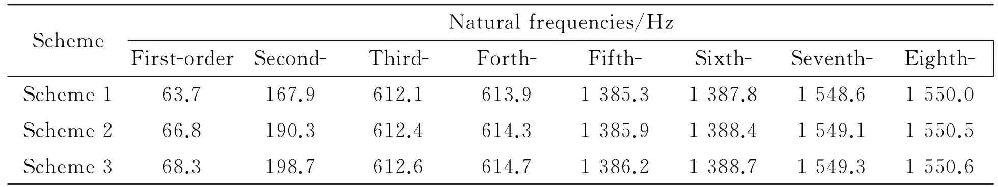
Table 2. Modal natural frequencies of the spindle system
5.Harmonic response analysis of spindle system
Figure 4 is a schematic diagram of the grinding force. When the gear is grinded, the grinding force can be decomposed into axial force, radial force and tangential force. Meanwhile, the tangential force is smaller than the radial force, so it can be ignored. The tangential grinding force is not signed in Figure 4. Because of the symmetry of the gear tooth profile, the axial grinding forces of the two tooth profiles can offset each other. In this paper, the radial force is taken as the amplitude of the simple harmonic motion. The purpose is to research the steady-state response of the spindle system under the pressure of the exciting force.

Figure 4. Schematic diagram of the grinding force
According to the papers, the formula of the radial grinding forceFrcan be defined as
(12)
In the formula,CFrepresents the energy required the removal of chips of per unit volume.uc,uwrespectively represent the speed of wheel and gear.fris the radial feed.Bis the grinding width.αrepresents the half angle of the abrasive.
The harmonic analysis is used to determine the steady-state response of the spindle system under the harmonic exciting force. The purpose of the harmonic response is to calculate the response curve correspondent to several frequencies of the spindle system. The peaks of the harmonic response will be found from the response curve. Depending on frequency characteristics curve, it is considered to verify whether the spindle system can overcome resonance, fatigue, and other hazards caused by forced vibration.
According to the natural frequencies calculated by the modal analysis, when the harmonic analysis is implemented, the frequencies range of the exciting force is set from 0 to 1 600 Hz, in order to study the deformation-frequencies response of spindle system within the frequency ranges. Studies have shown that, when the frequencies of the exciting force are the same as the natural frequencies of the spindle system, the peak response or resonance vibration will happen. Figure 5 is the deformation-frequency response curve. The five distinct peaks appear in the response curve. Their frequencies ranges are respectively from 50 to 80 Hz, from 150 to 200 Hz, from 550 to 700 Hz, from 1300 to 1 400 Hz, and from 1 500 to 1 600 Hz. The maximum deformation occurs in the vicinity of 600 Hz, and it reaches 6.56 μm. It can be shown that these frequencies just correspond to the first-order, the second-order, the third-order, the fifth-order and the seventh-order natural frequencies. Therefore, when the frequencies of the exciting force are within the vicinity of the natural frequencies, the resonance vibration of the spindle system will happen.

Figure 5. Deformation-frequency response curve
6.Critical speed of the spindle system
The critical speeds of the spindle system are corresponding to the speeds calculated by the natural frequencies. If the spindle system is operating at a critical speed, there will be severe vibration and noise. Thereby, machining accuracy will be greatly affected, and severe bending of the spindle will occur in the long run. The purpose of analyzing the critical speed is trying to make the spindle system work well. Meanwhile, the spindle speed should be as far as possible away from the critical speed to avoid the resonance vibration. According to the natural frequencies of the spindle system, it is calculated that the range of the first-order critical speed is from 3 800 to 4 100 r/min, and the range of the second-order critical speed is from 10 020 to 11 880 r/min. The maximum speed of Y7232 CNC worm wheel gear grinding machine is 7 000 r/min. In order to avoid resonance vibration, the spindle speed should try to avoid the first-order critical speed. As the spindle speed does not reach more than ten thousand per minute, the actual speed of the spindle system is far away from the second-order and higher critical speed and resonance vibration will not happen.
7.Conclusion
1) According to the modal analysis of the spindle system, it is found that the natural frequencies of the spindle system are influenced by the supporting stiffness. With the increase of the bearing stiffness, the natural frequencies of the spindle system have been increased, and the first two natural frequencies are greatly impacted by the supporting stiffness. It is also found that the wheel spindle is the weak link of the spindle system, and the bending vibration mode of the wheel spindle is the dominant mode shapes. So it may be considered to optimize the structure of the spindle system.
2) According to the harmonic analysis of the spindle system, it is found that, when the frequencies of the exciting force are in the vicinity of the natural frequencies, the resonance vibration of the spindle system will happen. Especially, if the frequency of the exciting force is close to 600 Hz, the maximum peak response will appear in the deformation-frequency response curve, and the maximum value is 6.56 μm.
3) The first-order critical speed and the second-order critical speed of the spindle system are calculated. Since the first-order critical speed is lower than the maximum speed of the spindle system, the operating speed of the spindle system should avoid the first critical speed in order to avoid the resonance vibration. The second-order critical speed is far greater than the maximum speed of the spindle, so the resonance will not occur.
[1] Luo Xiaoying, Tang Jinyuan.Effect of structure parameters on dynamic properties of spindle system[J].Journal of mechanical engineering, 2007, 48(3): 128-134.
[2] Yu Tianbiao, Wang Xuezhi, et al.Modal analysis of spindle system on ultra-high speed grinder[J].Journal of mechanical engineering, 2012, 48(17): 184-188.
[3] Cai Ligang, Ma Shiming, et al.Finite element modeling and modal analysis of heavy-duty mechanical spindle under multiple constraints[J].Journal of mechanical engineering, 2012, 48(3): 165-173.
[4] Tian Jie, Li Xiangbin.Dynamic analysis for electric spindle rotor system of magnetic levitation grinder considering grinding force[J].China mechanical engineering, 2010, 21(24): 3005-3008.
[5] Zhao Zhiguo.Vibration modal and harmonic analysis of spindle in mineral oil dish-style separator.Coal mine machinery.2011, 32(12):112-114.
[6] Wu Liangsheng, Zhou Liang.Dynamic performance for GDH512 motorized spindle[J].Mechanical technology and machine, 2010 (2):21-25.
摘要:设计了一种新型差动自感式磁流变阻尼器(DSMRD),研究中发现该阻尼器中的绕线缸体在磁场中容易产生漏磁现象。基于此现象,建立了不同绕线缸体材料的DSMRD磁场仿真模型,对绕线缸体构成材料与漏磁之间的关系进行了仿真分析。仿真结果表明:导磁缸体较不导磁缸体具有更好的磁场吸附能力,且能产生更高的感应电动势;采用铝和不锈钢这两种不导磁材料制成的绕线缸体产生的磁场强度接近,并且产生的感应电动势也基本相同。因此可通过改变绕线缸体材料来达到优化DSMRD的自感磁场和阻尼磁场的目的。
关键词:差动自感式磁流变阻尼器;绕线缸体;磁场仿真
中图分类号:TH137.5
数控蜗杆砂轮磨齿机主轴系统模态与谐响应分析
牟红刚†1,2,张金泉2,许祥根2,陈 烨2
1.南京理工大学,南京 210094;2.镇江江南矿山机电设备有限公司,江苏 镇江 212009
针对数控蜗杆砂轮磨齿机磨削过程中具有简谐振动的特点,建立其主轴系统的三维有限元模型。利用有限元分析软件ANSYS进行模态分析和谐响应分析。通过模态分析求解获得了主轴系统的固有频率和振型,并研究了角接触球轴承支承刚度对其固有频率的影响;通过谐响应分析获得了主轴系统的变形—频率响应曲线,最后通过计算临界转速来验证主轴系统是否发生共振。研究结果表明:增大角接触球轴承的支承刚度有利于提高主轴系统的固有频率。磨削激振力的频率在600 Hz附近时,变形—频率响应曲线出现了最大的峰值响应为6.56 μm。为了避免共振,主轴系统的工作转速应尽量避开一阶临界转速。
主轴系统;模态分析;谐响应分析;共振;临界转速
TG580.6
新型磁流变阻尼器绕线缸体材料对磁场性能的影响*
胡国良†1, 2,周 维1,茹 毅1,龙 铭1
1.华东交通大学 机电工程学院,南昌 330013;2.浙江大学 流体动力与机电系统国家重点实验室,杭州 310027
2014-01-20
10.3969/j.issn.1001-3881.2014.12.006
† Hong-gang MU, PhD. E-mail: mhg2007.love@163.com

- 机床与液压的其它文章
- A Simple time-domain method for bearing performance degradation assessment*
- Structural design and performance testing of the electromagnetic proportional pressure relief valve
- Analysis of magnetic field characteristics for different winding cylinder materials of a new type of magnetorheo-logical damper*
- Impacts of centrifuge errors on calibration accuracy of error model coefficients of gyro accelerometer*
- Interior ballistic simulation and parameter influence analysis of an underwater pneumatic launcher*
- Influence of airflow uniformity over the duct outlet of vehicle air-condition on cooling performance*