
Vibration characteristics analysis of cracked beams based on energy method*
2014-07-31 20:22chuanYANGYinghuiLIXiangZHAOLiangLI
机床与液压 2014年2期
E-chuan YANG, Ying-hui LI, Xiang ZHAO Liang LI
1School of Mechanics and Engineering, Southwest Jiaotong University, Chengdu 610031, China2College of Mechanical Engineering, Chongqing University of Technology, Chongqing 400054, China
Vibration characteristics analysis of cracked beams based on energy method*
E-chuan YANG†1,2, Ying-hui LI1, Xiang ZHAO1Liang LI1
1SchoolofMechanicsandEngineering,SouthwestJiaotongUniversity,Chengdu610031,China2CollegeofMechanicalEngineering,ChongqingUniversityofTechnology,Chongqing400054,China
The transverse vibration of the beam with opening cracks was studied in this paper. Continuous bending stiffness and shear stiffness of the beam were deduced, based on energy distribution,using energy method of fracture mechanics. Then, the vibration characteristics of cracked Timoshenko beams were calculated using matrix transfer method. Natural frequency attenuation, which fluctuates with the variation of crack parameters such as depth and location of a crack, was analyzed. Comparing the results with those obtained by the finite-element method, the validity of the method used in this paper was verified.
Cracked beam, Vibration characteristics, Continuous stiffness
1.Introduction
Beams are widely used in various engineering fields. Damages of beams will appear due to high load or other abominable working environment. Usually, the damages are marked firstly by the occurrence and extension of surface cracks. The cracks are important reason for structural failure. The research of vibration characteristics of cracked beams is the most important basic theory of the damage detection technology[1]. It need be analyzed quantitatively that how cracks will affect the vibration of a beam. At present, a number of efforts have been made to analyze how will crack parameters influence on the vibration characteristics of a beam[2-10].
Crack modeling is always the key to study the vibration of a cracked beam, there are two widely used methods to model opening cracks in beams: the weaken section method[3-4] and the local flexibility method[5-7]. Both of the methods are to simulate the stiffness just at the section where the cracks occur. However, in fact, the crack will cause continuous stiffness attenuations near the crack region. Swamidas and Yang established the continuous bending stiffness and shear stiffness of a cracked beam based on energy theory of fracture mechanics[8]. This model reflects the stress concentration of crack area, while taking the stiffness attenuation nearby the crack section into account. In this paper, based on the continuous stiffness model and matrix transfer method, vibration characteristics of cracked Timoshenko beam were calculated. Comparing the results with those obtained by the finite-element method, the validity of the method used in this paper was verified. Meanwhile, by examples in this paper, natural frequency attenuation of the first three orders, which fluctuates with the variation of crack parameters such as depth and location of a crack, was analyzed.
2.Energy expressions of cracked beams
Suppose a cracked beam is subjected to a constant bending moment, if the crack has extended for Δa, the bending moment will perform some work, that will not only makes the crack growth, but also increases the strain energy of the beam:

(1)
Where,Sis the energy for crack growth, ΔUis the elastic strain energy increment of a cracked beam.
Using the Clapeyron’s theorem, it can be inferred that for a cracked beam the work (W) done by stable external force or moment was twice the elastic strain energy increment (ΔU)[9]:

(2)
It can be obtained that:
(3)
3.The continuous stiffness of cracked beams
3.1.The energy for crack growth
When a crack is formed in one side of the beam, suppose that crack depth increases from 0 to a under constant bending moment, according to the theory of fracture mechanics, the energy needed for crack growth is:
(4)
Where,bis the width of beam,ais the crack depth,Gis strain energy release rate. Under the bending momentGcan be expressed as:
(5)
Where,KIis stress intensity factor for the first mode crack (opening crack),Eis Young Modulus.

Figure 1. Diagrammatic sketch of a cracked beam
A beam with a rectangular section and an opening crack is shown in Figure 1,KIcan be expressed as[10]:
(6)
Where,F(a/h) is shape coefficient associated witha/h. Ifa/h≤0.6, a tabular format is given as
(7)
Substitution of Eq. (6) and (5) into (4) yields:
(8)
3.2.The elastic strain energy increment of cracked beams
If the ΔUin Eq. (2) is considered as a continuous function along the beam, such that:
(9)
From fracture mechanics, the stress is highly concentrated around the crack region, so we can assume that the elastic strain energy increment of a cracked beam (ΔU) is also concentrated mainly around the crack region too. The distribution of ΔU(x) along the length of a beam can be expressed as[8]:
(10)
Where,Q(a,c) andk(a) are terms to be determined,cis the distance to the crack iocation from one end of the beam.
3.3.Continuous stiffness model
For a beam with an opening crack, IntroducingEIC(x) as continuous bending stiffness, that means the bending stiffness of cross-section changes continuously along length direction of the beam. So, the total strain energy of the cracked beam can be expressed as:
(11)
Prior to crack occurrence, for a beam under a constant momentM, the bending stiffness isEI, strain energy of the beam can be expressed as:
(12)
Therefore, total strain energy of cracked beam can be expressed as:
(13)
Substitution of Eq.(8),Eq.(9),Eq.(11) and (12) into (13) yields:
(14)
From Eq. (14), the continuous bending stiffness of cracked beam is obtained as[8]:
(15)
Where,EIis bending stiffness of the beam ignoring cracks,xis the longitudinal coordinates along the beam,EIR(a,c) andk(a) are terms related to the depth and position of the crack. For rectangular section beams the expressions can be determined as:
(16)
(17)
In the equation (16) and (17),lis the length of the beam andhfor height of beam section.
By the same derivation processes, continuous shear stiffness of cracked beam can obtained as:
(18)
Where,GAis shear stiffness of the beam ignoring cracks.
For a rectangular section beams, take the parameters asl=1 000 mm,h=100 mm,c=l/2,a=h/2, the continuous bending stiffness (EIC(x)) and continuous shear stiffness (GAC(x)) were calculated from Eq.(15) and (18), and shown in Figure 2.

Figure 2.Continuous bending and shearing stiffness
As Figure 2 shows, for a beam with a crack occurs in the midpoint of the beam and crack deptha=h/2, stiffness attenuation is very significant in the crack section. However, it is worth noting that the stiffness attenuation is also obvious at the region near the crack location, about 1/6 length of the beam.
4.Examples
Based on the continuous conditions (continuous displacement, rotation, bending moment and shear force), the relationships of the mode function between two adjacent segments can be established. Using matrix transfer method, the relationships of the mode function between the first and the end segment can also be derived. With given boundary conditions of end points of a beam, the characteristic equations can be built, and the natural frequency can be calculated by using Newton-Raphson method[11-12].
4.1.The verification of validity
To verify the validity of the method used in this paper, the first three natural frequencies of a simply supported Timoshenko beam (a rectangular cross section beam, lengthl=1 000 mm, widthb=100 mm, heighth=100 mm) with an opening crack was calculated and the results were compared with those obtained from finite element method. The ANSYS software was selected for finite element calculation, using the element type of SOLID 65 for simulation.
The first three natural frequencies, with different crack depth(a/h=0,a/h=0.3 anda/h=0.5), obtained from two methods are listed in Table 1, which are in good agreement with one another. When the crack depth is relatively shallow, the maximum error between the two methods is very small. When the crack depth is deeper, the error value increases, but the maximum error in Table 1is only 3.81%. With the error analyses above, the conclusion can be drawn that the method used in this paper is accurate enough to model the beams with opening cracks.
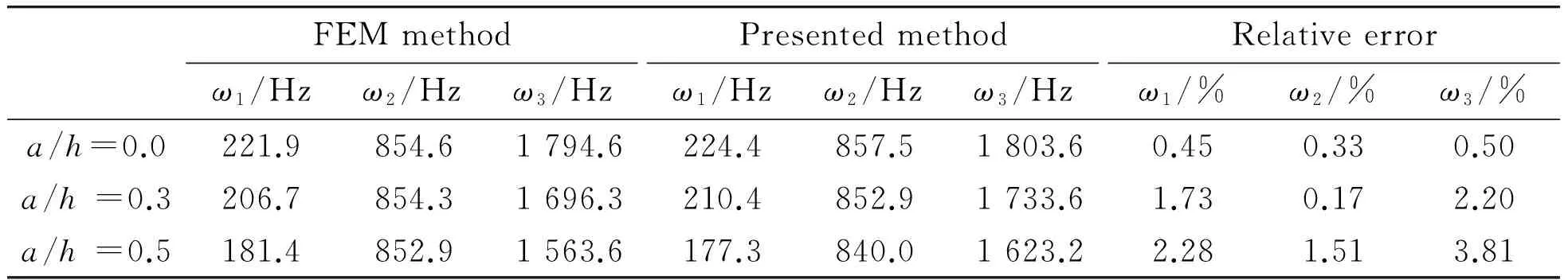
Table 1. Natural frequencies for a cracked Timoshenko beam (l/h=10)
4.2.The effect of crack depth on natural frequencies
Also take the rectangular section beam for example, which has been used above. Suppose the crack occurs in the midpoint of the beam. To analyze the effect of crack depth on natural frequency, the first three natural frequencies of the beam were calculated, as crack depth (a/h) change continuously from 0 to 0.5.ωciandωirespectively means theith natural frequency of the cracked beam and uncracked beam. In Figures 3 to 5, theωci/ωiis taken to express the frequency attenuation caused by cracks.
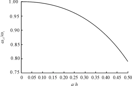
Figure 3. The first frequency attenuation(c=l/2)
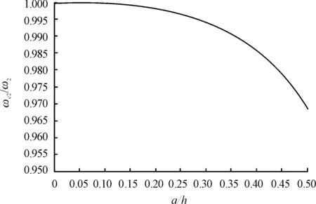
Figure 4. The second frequency attenuation (c=l/2)
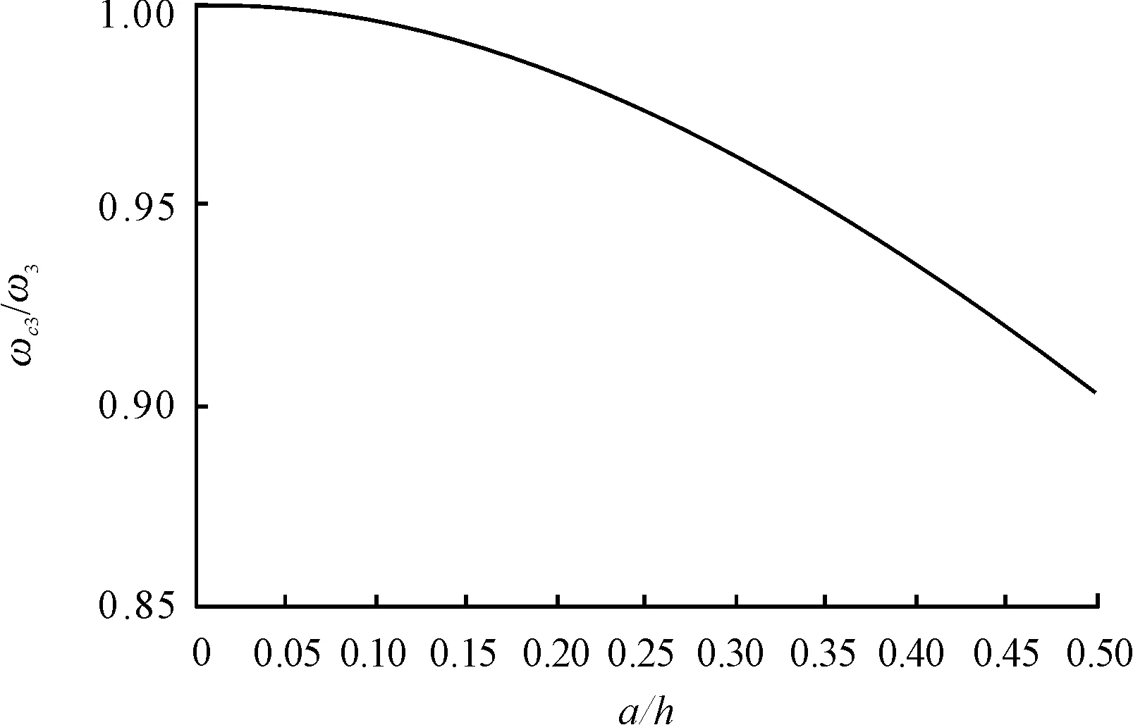
Figure 5. The third frequency attenuation (c=l/2)
The attenuation of the first three natural frequencies , caused by cracks with different crack depths are shown in Figures 3~5. It can be seen that the frequency attenuation can be sorted as: the first order>the third order>the second order. It is because the crack occurs in the midpoint of the beam(c=l/2). In this case, the crack has little impact on second frequency, even crack depth reaches half the height of the cross section (a/h=0.5),ωc2/ω2is 0.979 6, the frequency attenuation is about 2% and is not obvious.
When the crack depth is shallow (a/h≤0.2), the attenuations of first and third frequency are also not obvious. The maximum attenuation rate of first frequency is 2.63%. The frequency attenuations become gradually obvious while the crack be deeper. When the crack depth increases (such asa/h=0.4), the maximum attenuation rate of first frequency reaches 12.03%, while that of third frequency is 6.54%. When crack depth reaches half the height of the cross section (a/h=0.5), the frequency attenuation of the cracked beam will become more significant, the maximum attenuation rate of first order frequency reaches 21.0%, while that of third order frequency is 9.99%.
4.3.The effect of crack location on natural frequencies
Assuming that the crack varies continuously fromC= 0 toC=L, crack depth is fixed (a/h=0.5), other parameters of the beam are the same to the previous example. To analyze how the crack position will affect on the natural frequency, the attenuation curves of the first three natural frequencies are shown in Figures 6~8.
According to the results, for each frequency, when the crack is close to the position of a modal node, crack has tiny impact on the frequencies. If the crack is just overlap the position of a modal node, the attenuation of the second frequency is 3.2%, while 4.0% for the third frequency (see Figure 7 and Figure 8). When the crack is close to the position, where occurs the biggest mode displacement, it has more significant impact on the frequency. However, the sensitivity of each frequency is not the same. It can be found that, as the modal order increasing, the frequency becomes less sensitive to the crack. For example here (a/h=0.5,l/h=10), the maximum attenuation of the first frequency is 21.7%, while 14.8% and 10.8% for the second and third frequency (as shown in Figures 6~8).

Figure 6. The first frequency attenuation (a/h=0.5)
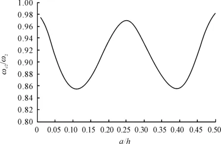
Figure 7. The second frequency attenuation (a/h=0.5)
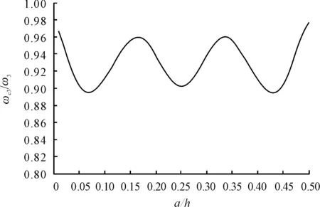
Figure 8. The third frequency attenuation (a/h=0.5)
5.Conclusion
In this paper, using energy method, continuous bending and shear stiffness model of cracked beams were obtained. By means of transfer matrix method and Newton-Raphson method, first three natural frequencies of cracked Timoshenko beams were calculated. By comparing the results with those obtained by finite element software, it was proved that the method used in this paper is valid with good accuracy.
At the same time, through the analysis of examples, this paper summarized the influence of crack depth and crack position on the first three natural frequencies. It concludes that, frequency attenuation is not obvious when the crack depth is shallow (a/h≤0.2).However, as the crack deepening, frequency attenuation becomes more obvious. In the examples given in this paper, as the crack depth increases, or a/ h varies from 0.2 to 0.5, the maximum attenuation of the first order frequency increases from about 3.0% to about 20%. In addition, the location of cracks also impacts on the frequency attenuation of a cracked beam. When the crack position is close to a modal node, the influence is very weak. Inversely, when the crack close to the position, where occurs the biggest mode displacement, it has more significant impact on the frequency. Moreover, the Sensitivity of each order frequency to crack is not the same, as the modal order increasing, the sensitivity of the frequency to cracks presents a declining trend.
[1] Dimarogonas A D.Vibration of cracked structure:a state of the art review[J].Engineering Fracture Mechanics,1996,55(5):831-857.
[2] Hu Jiashun, Feng Xin, LI Xin, et al. State-of-art of vibration analysis and crack identification of cracked beams[J]. Journal of Vibration and Shock,2007, 26(11):146-152.
[3] Irwin G R. Analysis of stresses and strains near the end of a crack traversing plate[J]. Journal of Applied Mechanics. 1957,24:361-364.
[4] Petroski H J.Stability of a crack in a cantilever beam tinder going large plastic deformation after impact[J].International Journal of Pressure Vessels and Piping,1984,16(4):285-298.
[5] Zheng D Y, Fan S C. Vibration and stability of cracked hollow-sectional beams[J]. Journal of Sound and Vibration, 2003, 267(4):933-954.
[6] Papadopoulos C A, Dimarogous A. Coupled longitudinal and bending vibrations of a rotating shaft with all open crack[J]. Journal of Sound and Vibration,1987,117(1):81-83.
[7] Lin Yanli, Guo Xinglin.characteristics of vibrational power flow of a cracked periodically supported infinite beam[J].Journal of Dalian University of Technology,2004,44(2):184-185.
[8] Swamidas A S J, Yang X, Seshadri R. Identification of cracking in beam structures using Timoshenko and Euler formulations[J]. Journal of Engineering Mechanics, 2004, 130(11):1297-1308.
[9] Yang X F, Swamidas A S J, Seshadri R. Crack identification in vibration beams using energy method[J]. Journal of Sound and Vibration, 2001, 244(2):339-357.
[10]Almar-Neass,A.Fatigue handbook: offshore steel structures[M].Trondheim,Norway:Tapai,1985:144-156.
[11]Cui Can, Du Changcheng, Li Yinghui. A new rapidly method for vibration characteristic of stepped beam[J].Journal of Sichuan University (Engineering Science Edition), 2011, 43(Supplement 2):33-36.
[12]Qian Bo, Yue Huaying. Numerical calculation of natural frequency of transverse vibration of non-uniform beams[J].Mechanics in Engineering, 2011,33(6):45-49.
基于能量法的裂纹梁振动特性分析*
杨鄂川†1,2,李映辉1,赵 翔1,李 亮1
1.西南交通大学 力学与工程学院,成都 610031;2.重庆理工大学 机械工程学院,重庆 400054
研究了含常开裂纹梁的横向振动,基于断裂力学中的能量法,推导了裂纹梁基于能量分布的连续弯曲及剪切刚度表达式;而后基于矩阵传递法,计算了含裂纹Timoshenko梁的振动特性,分析了裂纹深度及位置等裂纹参数对固有频率衰减的影响,同时将计算结果与有限元软件计算结果进行了比较,验证了该方法的有效性。
裂纹梁; 振动特性; 连续刚度
O321
2014-03-21
10.3969/j.issn.1001-3881.2014.12.007
*Project supported by the National Natural Science Fund(11072204) and Central Scientific Research Fund of Colleges and Universities(SWJTU11ZT15)
† E-chuan YANG, PhD. E-mail:yangechuan@sina.com
猜你喜欢
舰船科学技术(2022年20期)2022-11-28
中国机械工程(2022年22期)2022-11-25
中国机械工程(2022年7期)2022-04-20
甘肃科技(2020年20期)2020-04-13
中国机械工程(2019年17期)2019-09-19
World Journal of Diabetes(2019年7期)2019-07-23
中国机械工程(2018年4期)2018-03-06
四川轻化工大学学报(自然科学版)(2017年3期)2017-06-29
火炸药学报(2014年3期)2014-03-20
电力自动化设备(2013年11期)2013-09-18

- 机床与液压的其它文章
- A Simple time-domain method for bearing performance degradation assessment*
- Structural design and performance testing of the electromagnetic proportional pressure relief valve
- Analysis of magnetic field characteristics for different winding cylinder materials of a new type of magnetorheo-logical damper*
- Impacts of centrifuge errors on calibration accuracy of error model coefficients of gyro accelerometer*
- Interior ballistic simulation and parameter influence analysis of an underwater pneumatic launcher*
- Influence of airflow uniformity over the duct outlet of vehicle air-condition on cooling performance*