
Design and realization of signal acquisition digital system for leak detection of water supply pipeline*
2014-07-31 20:22HongliLYUCuiyingDONG
机床与液压 2014年2期
Hong-li LYU, Cui-ying DONG
Department of Information Engineering, Tangshan College, Tangshan 063000, China
Design and realization of signal acquisition digital system for leak detection of water supply pipeline*
Hong-li LYU†, Cui-ying DONG
DepartmentofInformationEngineering,TangshanCollege,Tangshan063000,China
Since the leakage signals have some characteristics such as low amplitude and wide dynamic range, it is difficult to catch these signals in the real industrial applications. In this paper, a leakage signal acquisition system, which has some unique characteristics such as low noise, low power consumption and easy to be adjusted according to the practical settings, is analyzed and designed. Based on the SCM, this system is capable for signal acquisition and data communication with DSP. It could satisfy the requirements of leak detection and data acquisition in outdoor long-distance operation mode.
Leak detection, Signal adjust circuit, Data acquisition, RS-485, SCM
1.Introduction
As far as urban water supply system is concerned in our country, the leakage of water supply pipeline could cause serious water loss at each year[1]. Therefore, how to develop the instruments for pipeline to monitor and position the leakage is a new promising research subject. Since the data used to detect the pipeline leakage have a direct impact on the leakage position accuracy for the pipeline, the data acquisition system becomes very important to determine the leakage position of pipeline[2-4].
2.Theory of correlation detection of pipeline leakage
The schematic diagram of correlation detection is shown in Figure 1[5-6]. The leakage signal travels in two directions with the velocityv. The symbolL1andL2stand for the distance from 1# and 2# sensor to the leakage position. The time difference of the signal arrival the two sensors is called time delay and is symbolizedD. The distance between the two consecutive sensors is symbolized asL. According to the similarity of the two signals, the peak value of correlation function could be obtained and the time delayDcould be evaluated and then the leakage position could be is determined. The distance from leakage position to 1# sensor isL1and it could satisfy the following formula.
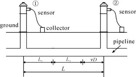
Figure 1. The principle of correlation detection
3.Control scheme for signal acquisition system
Due to the different material of pipeline, diameter of pipeline and shape of leakage position, the frequency distribution of leakage signal could vary in a relative big range. The frequency range of water leakage sound signals for the metal pipeline is from 500 Hz to 3 500 Hz[7]. Since the water leakage signal is transmitted through soil to ground, the amplitude of this signal could be decreased. Based on the on-site field measurement, the frequency range of leakage sound is always between 100 Hz and 700 Hz which could be detected from the ground. Therefore, the accelerometer is needed in the system to measure the vibration signal. According to the principle of correlation detection, the signal acquisition system should simultaneously obtain these two signals.
Since the obtained signals from the two sensors are weakened and there exist some noise signals, the signal adjustment circuit is designed to amplify and filter the noise signals. And then the signals will be converted into digital signals through the A/D chip and these digital signals could be saved by single-chip microcontroller (SCM). Because there exist some distance between the consecutive two sensors and various signals are stored by the main SCM, the data transmission is necessary and it is selected as RS-485. In order to obtain the real-time analysis for this system, a DSP chip is adopted to realize the complex algorithm for correlation detection theory and the RS-485 is used for the data transmission between the main SCM and DSP. The control scheme diagram for signal acquisition system is shown in Figure 2.
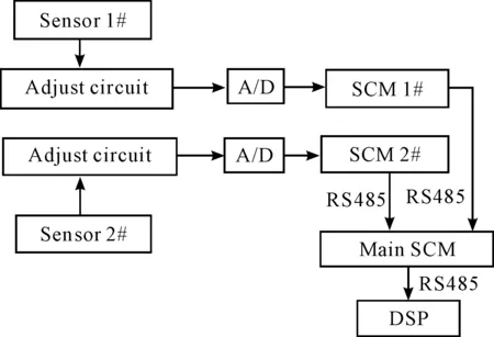
Figure 2. The system control scheme diagram
4.Design of the signal adjustment circuit
The signal adjustment circuit consists of amplification circuit and filter circuit.
4.1.Design of the signal amplification circuit
The leakage signal has relatively high dynamic range and is seriously affected by the outside environment. If the fixed-gain amplifier is adopted for the signal acquisition system, there exist some problems for the signals such as insufficient amplification or saturated amplification. Therefore, the adjustable-gain amplifier should be selected and the dynamic gain range is between 0 dB and 32 dB. As shown in Figure 3, it is presented the signal amplification circuit with the chip NE5532, and the gain of this circuit could be adjusted by modulating the resistance value of R4.
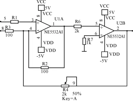
Figure 3. Signal amplifying circuit with NE5532
4.2.Design of the signal filter circuit
The maximum limit of high frequency components for leakage signal is 3 500 Hz and the frequency bandwidth of noise is relatively wide, therefore the low pass filter is needed for the design of the filter circuit. Since the elliptic filter is one of the low pass filters and it has the minimal pass-band and stop-band ripple as compared with other filters, this kind of filer is adopted in this paper. As shown in Figure 4, the elliptic filter circuit with chip LTC1068 is presented and the cut-off frequency is 3 500 Hz and the pass-band gain is 0 dB.

Figure 4. Signal filtering circuit
4.3.Hardware design for low noise and low power consumption
The signal amplification circuit could magnify the output signal of the sensor; however, at the same time the noise could be produced. In order to control the noise signal and prevent the signal pollution during the amplification process, the low noise components is selected for the circuit design, such as metal film resistor, field-effect tube, Rail-to-Rail device for integrated operational amplifier.
In order to adapt to the water pipeline leakage detection of outdoor working environment, the signal acquisition system is needed to be powered by a battery. Therefore, the system has the requirement for the low power consumption. Due to this reason, the SCM is selected to be the processor because it has relatively low power consumption characteristics as compared with other embedded processors. In addition, the low power devices meet the requirements for the design of the peripheral circuit and Lithium- ion battery of high energy density could be used in the real industrial applications.
5.Software design
After power on and initialization, the two SCM will wait for the instructions from the main SCM through RS-485 bus. Once the data acquisition instruction is received, the A/D chip will get started and the leakage signals could be obtained and saved. The saved data will be transmitted to DSP through RS-485 bus. The program flow chart of main SCM is illustrated in Figure 5.
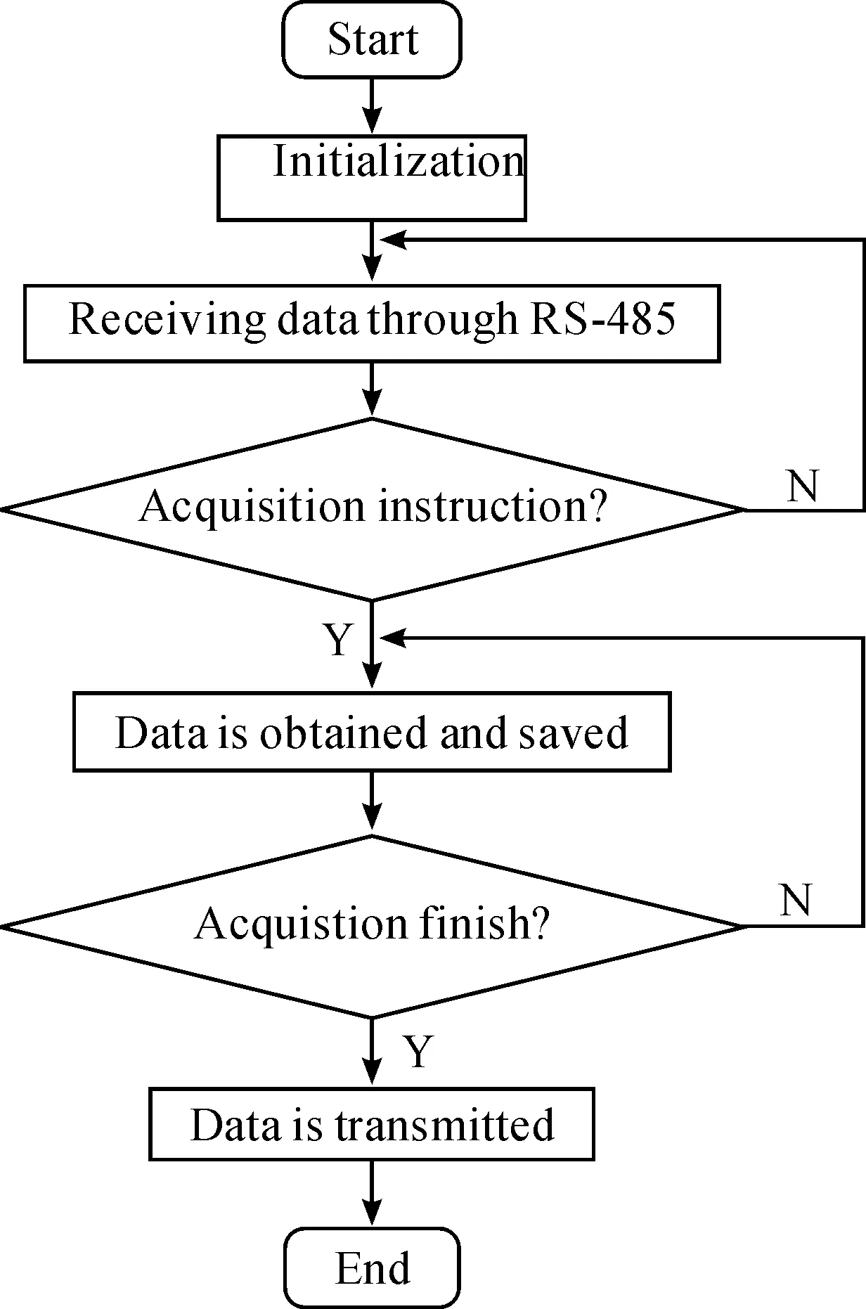
Figure 5. Program flow chart of data acquisition system
6.Conclusion
The leakage signals are simulated by signal generator and the peak-to-peak voltage amplitude is 500 mV and frequency is 1000 Hz. These signals will be adopted as the input signals for the signal adjustment circuit. The peak-to-peak voltage amplitude of output signals from adjustment circuit is 4 V. As shown in Figure 6, it is presented the input and output simulated waveforms for signal adjustment circuit. This demonstrates that the magnification factor of signal amplification circuit is eight.
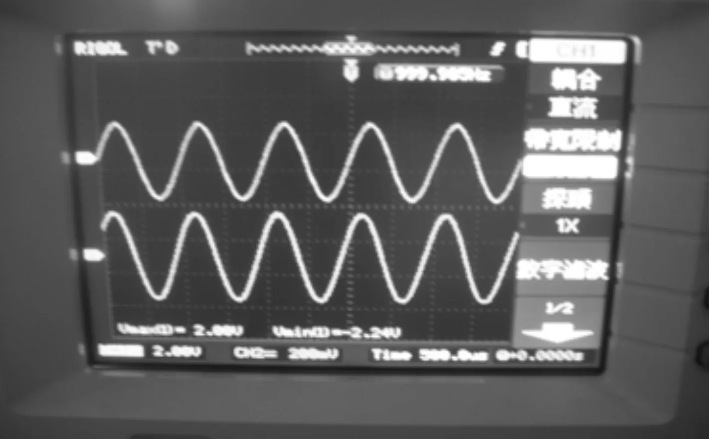
Figure 6. The input and output simulated waveform of signal adjust circuit
Figure 7 is the model machine of signal acquisition system and Figure 8 is the waveform recorded in the field testing for water pipeline leakage. The data stored in SCM is transmitted to DSP by RS-485 and the complex filtering algorithm and localization algorithm are achieved by DSP.
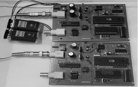
Figure 7. The signal acquisition system prototype
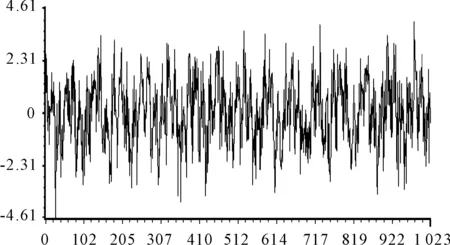
Figure 8. The waveform recorded in the field testing
The designed leakage signal acquisition system has low noise and low power consumption. It is capable to match the outdoor working environment for leakage detection and could be applied to the petroleum, gas or other pipelines.
[1] Qian Yi,Liu Changming.Sustainable development of water resource in Chinese urban[M].Beijing: China Water Power Press,2002.
[2] Wang Ji-hua,Peng Zhen-bin,Guan Xiang-feng.Leakage testing techniques and prospect for ductwork of water supply[J].Journal of Guilin institute of technology,2004,24(4):456-460.
[3] Pilcher R,Hamilton S,Chapman H,et al.Leakage location & repair guidance notes version 1[J].Water Loss Task Force,IWA.2007(3):12-18.
[4] Shu Shi-hu,He Wen-jie,et al.Current Application and Recent Development of Leakage Detection Technologies in Water Supply Networks[J].Journal of water & wastewater engineering,2008,34(6):114-116.
[5] Brennan M J,Gao Y,Joseph P F.On the relationship between time and frequency domain methods in time delay estimation for leak detection in water distribution pipes[J].Journal of Sound and Vibtation,2007,304:213-223.
[6] Gao Y,Brennan M J,Joseph P F,et al.On the selection of acoustic/vibration sensors for leak detection in plastic water pipes[J].Journal of Sound and Vibtation,2005,283:927-941.
[7] Feng Ying-jian.Research on leakage detection system of city water pipeline[D].Shenyang: Shenyagn University of Technology,2008.
供水管道泄漏信号采集系统的设计与实现*
吕宏丽†, 董翠英
唐山学院 信息工程系, 河北 唐山 063000
针对供水管道泄漏信号幅度低、动态范围大的特点,设计了管道泄漏信号采集系统。该系统具有低噪声、低功耗特性,而且采集参数动态可调。系统实现以单片机为核心,完成了数据采集并实现与DSP的数据通信,能够满足户外长距离管道泄漏信号数据采集的要求。
泄漏检测;信号调理电路;数据采集;RS-485;单片机
TP274
2014-03-01
10.3969/j.issn.1001-3881.2014.12.018
*Project supported by Science and Technology Support Program of Hebei Province(13276201D)
† Hong-li LYU, Associate professor. E-mail: LHL741127@163.com
猜你喜欢
供水技术(2022年1期)2022-04-19
建材发展导向(2021年22期)2022-01-18
河北金融年鉴(2021年0期)2021-08-25
成都信息工程大学学报(2021年1期)2021-07-22
供水技术(2021年2期)2021-07-16
动漫星空(兴趣百科)(2020年6期)2020-06-17
东方艺术·国画(2016年3期)2017-02-08
公民与法治(2016年20期)2016-05-17
东北电力大学学报(2015年4期)2015-11-13
电子设计工程(2014年17期)2014-02-27

- 机床与液压的其它文章
- A Simple time-domain method for bearing performance degradation assessment*
- Structural design and performance testing of the electromagnetic proportional pressure relief valve
- Analysis of magnetic field characteristics for different winding cylinder materials of a new type of magnetorheo-logical damper*
- Impacts of centrifuge errors on calibration accuracy of error model coefficients of gyro accelerometer*
- Interior ballistic simulation and parameter influence analysis of an underwater pneumatic launcher*
- Influence of airflow uniformity over the duct outlet of vehicle air-condition on cooling performance*