
Research on Synchronization Technology of DSSS Signal Based on UQPSK
2015-02-20 05:39ZHANGBoFENGYongxin
沈阳理工大学学报 2015年3期
ZHANG Bo,FENG Yongxin
(Shenyang Ligong University,Shenyang 110159,China)
Research on Synchronization Technology of DSSS Signal Based on UQPSK
ZHANG Bo,FENG Yongxin
(Shenyang Ligong University,Shenyang 110159,China)
In communication systems operating over satellite links,increasing requirement is now being made of unbalanced quaternary phase shift keyed (UQPSK) signals.The signal format is a QPSK signal in where the two orthogonal components of the carrier have unequal power and are modulated with independent binary data streams of different rates.This transmission scheme is most useful when the data of two different sources with possibly varying rates have to be transmitted in the same frequency band.This feature can be applied to solve the problem of parallel transmission of inter-satellite link (ISL) ranging signal and data information.The direct sequence spread spectrum (DSSS) signal based on UQPSK is introduced into inter-satellite link communication system of navigation satellites.The research is focused on synchronization technology of UQPSK DSSS signal and design of synchronization loop.The establishment of communication system proves the correctness of the synchronization loop.
UQPSK;inter-satellite link;synchronization
Nowadays,there are 4 major global satellite navigation systems in the world,the GPS of United States of America,the GLONASS of Russian global navigation satellite system,the Galileo of European system and Chinese Beidou (Compass) system.GPS is the only satellite navigation system with inter-satellite link,which use TDMA (Time Division Multiple Access) and spread spectrum system in 250~290MHz frequency band.However,the GPS data transmission rate is low and it is difficult to meet more demand in the future.
The modernization of the inter-satellite link not only requires the ability of good inter-satellite ranging accuracy,but also needs a better data transmission rate.Taking into account the measurement precision and data transmission rate of inter-satellite link system,DSSS signal based on UQPSK is put forward.UQPSK is one kind of data modulation that can transfer two signals of different types and rates at the same time.Among them,the Q branch (quadrature) is used for the inter-satellite ranging with long period spread spectrum code and high data rate,of which purpose is to make the data transmission rate higher and better confidentiality.The I branch (in-phase) is used for the transmission of data between satellites with a low data rate and short cycle spread spectrum code,of which purpose is to achieve high spread spectrum gain,to improve the acquisition sensitivity of signal and meet the requirements of rapid acquisition.On the premise of measurement accuracy,I branch can try to use low transmit power.Use the most power for the data transmission of Q branch to ensure the communication quality and reduce the bit error rate.Because of the two branch signals strictly coherent,successfully acquisition of I branch can assist the Q branch direct signal tracking,which reduces the requirements on the sensitivity of the Q branch.Inter-satellite link using spread spectrum has the characteristic of strong anti-interference ability and higher ranging precision.Adopting UQPSK system can enhance the speed of data transmission between satellites and meet the requirements of modern.In addition,this signal system also realizes the integration of measurement and communication,which breaks the traditional separation condition that combines measuring equipment with communication equipment,improves the system integration degree and saves the satellite resources.
1 UQPSK SIGNAL
UQPSK signal mode:The UQPSK signal can be expressed as:
Spread spectrum waveformPN1is the Gold code,cycle of 1023 symbols,which is known as the short code;PNQis the long cycle spread spectrum code which cycle is 256 times of short code,called long code;Two spread spectrum code rates are the same about 3Mbps;∂Tcis phase error of the code;ωcis carrier frequency;ωdis doppler frequency shift;θis phase error;m1(t) is ranging code in I branch andmQ(t) is data information in Q branch.
The UQPSK signal is generated as shown in following figures:

Figure 1 Time domain simulation diagram
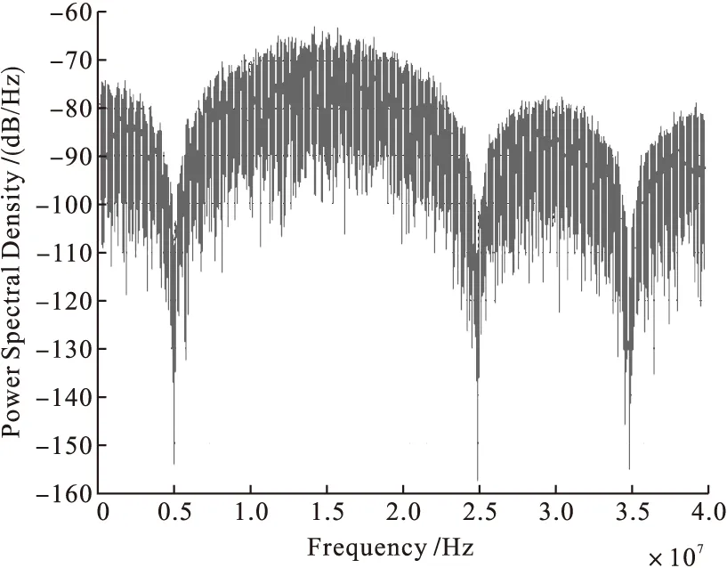
Figure 2 Spectrogram of UQPSK
2 SYNCHRONOUS RECEIVING LOOP
Because UQPSK combines ranging signal with the data signal to make communication between satellites,and the ranging signal can be regarded as synchronous information of the data signal .When coarse synchronization of ranging signal is successful,the data information can start the process of fine synchronization.Synchronous design diagram is shown in Figure 3.
2.1 Coarse synchronization design for in-phase branch
Overall,the coarse synchronization of I branch can be seen as a coarse synchronization of DSSS signal based on BPSK and the traditional running correlation synchronization method with complex equipment and long acquisition time does not meet the requirements of fast ranging in inter-satellite link.In order to achieve fast coarse synchronization,this paper uses the method of cyclic correlation and Doppler compensation to realize coarse synchronization.

Figure 3 Synchronous loop
Ranging signal of in-phase branch (I branch) coarse synchronization process:Firstly,the received signals are treated separately,isolated the I branch and quadrature branch (Q branch).Then preprocess I branch signal and filter out signal power spectrum in the effective bandwidth;Make the filtered signal mixing process to produce multi-channel signal for the acquisition of Doppler frequency;Make FFT operation on multi-channel signal,and take the conjugate of results;Get the local signal mean,and then make FFT operations,multiply the results and multi-path FFT conjugate results of the received signal.Do IFFT operations and take the absolute value.Comparison of the two results,calculate the maximum ratio of peak;Compared the maximum with threshold,if more than the decision threshold,enter the fine synchronization loop;Otherwise,adjust the locally code sequence to restart coarse synchronization.
2.2 Fine synchronization design for quadrature branch
After the success of coarse synchronization,start the fine synchronization of Q branch.In terms of Q branch signal,can adopt the incoherent full time advance-lag locked loop as the code fine synchronization loop.
This kind of fine synchronization loop adopts two independent correlators for correlation operation: advanced code (early code) correlator and lag code (late code) correlator.The input signal is divided into two:one accomplishes correlation operation on advanced local reference code and the other one accomplishes correlation operation on lag local reference code.After accumulation,square,addition and subtraction the results complete phase demodulation.
Fine synchronization loop consists of code correlator,loop filter,code NCO (Numerically-controlled oscillator) and code generator.Among them,code correlator serves as phase demodulation.The digital signal is divided into two parts which enter the code correlator after multiplied by the local carrier I and Q branches.Respectively make correlation operation on early,late two PN code,and get four results .Then obtain the phase error signal with addition and subtraction.The phase error signal through the loop filter is used to modify the frequency control word of NCO,changing the output frequency of NCO with the dynamic change of the input frequency.The loop filter can not only eliminate the noise,but also can be good to track dynamic signal.
3 SYNCHRONOUS SIMULATION
Simulation of the synchronization loop was carried out in Matlab environment with center frequency of 15MHz,the sampling frequency of 80MHz,Doppler (-2kHz~2kHz),the transmission time of 0.5ms. I branch used C/A code with code rate of 1Mbps.Q branch used the PN code with code rate of 5Mbps.M=10,meant that Q branch′s power was 10 times than I branch′s.
Accomplish coarse synchronization of I branch signals in different code migration and Doppler shift,and get the correct code offset and Doppler compensation value.So the Q branch signal can normally enter the fine synchronization loop.There are figures for simulation results.

Figure 4 The results of synchronization simulation(1)
As shown in Figure 4,in the case of initial code offset 60,the Doppler shift 700Hz through the simulation we had got that number of code offset was 60 and Doppler compensation value was 700Hz.The maximum ratio of peak was 24.988 which was more than the decision threshold.Coarse synchronization was success.

Figure 5 The results of synchronization simulation(2)
As shown in Figure 5,in the case of initial code offset 120,the Doppler shift 300Hz,through the simulation we had got that number of code offset was 120 and Doppler compensation value was 300Hz.The maximum ratio of peak was 29.611 which was more than the decision threshold.Coarse synchronization was success.
Test the ability of synchronization loop under different signal-to-noise ratio (SNR) in the condition that code offset and carrier frequency shift were certain.We had the results that the synchronization loop with low SNR could still work normally.Figure 6 shows the relationship of SNR and the ratio of peak.

Figure 6 The the relationship of SNR and the ratio of peak
Enter the fine synchronization loop and the initial offset was one symbol length (28 sampling points).Information to be transmitted were+1,0 and+1.Through the fine synchronization loop had successfully found code offset position and made code offset compensation to the local codes so that local codes and the received signal got synchronization.After that,demodulate the information data of Q branch.The Phase of output error is shown in figure 7.The demodulated output signal is shown in figure 8.

Figure 7 Phase of output error

Figure 8 The demodulated output signal
4 CONCLUSION
According to the simulation results,the correctness of the synchronization loop has been verified by the successful synchronization of signal in different code offset,Doppler shift and SNR.At the same time prove that the direct sequence spread spectrum signal based on UQPSK with high measurement accuracy and data rate can be used to inter-satellite link communication system.Moreover,this modulation has saved the satellite resources,which can provide reference for the design of the next generation of inter-satellite links.
REFERENCES:
[1]XU Haiyuan,HUANG Zhitao,ZHOU Yiyu.Detection and Performance Analysis of UQPSK DSSS Signals in Satellite Communication Applications[J].SIGNAL PROCESSING,2008,24(3):361-365.
[2]ZHENG Jinjun,LIN Yiming,CHEN Honggui.GPS Crosslink Technology and Autonomous Navigation Algorithm Analysis[J].SPACECRAFT ENGINEERING,2009,18(1):28-35.
[3]HE Shanbao,LIN Yiming,Wu Lenan.Design of New Signal System for Inter-satellite Links[J].Chinese Space Science and Technology,2011,7(2):15-21.
[4]WANG Nuo,DAI Yimin.Performance Analysis UQPSK Carrier Acquisition and Tracking Algorithm in Satellite Communications[J].ACTA ELECTRONICA SINICA,2011,5(2),15-21.
[5]Enrico Del Re,Marina Ruggieri.Satellite Communications and Navigation Systems[M].New York:Springer,2008.
[6]Hill DA,Bodie JB.Carrier detection of unbalanced QPSK direct sequence signals[A].IEEE MILCOM’ 99[C].Atlantic City:Oct-Nov,1999:437-441.
(责任编辑:马金发)
1003-1251(2015)03-0090-05
TP393.04 Document code: A
Received date: 2013-12-06
Biography: ZHANG Bo (1989—),male;FENG Yongxin (1974—),professor,doctor.Research direction:Spread spectrum communication technology and application.
猜你喜欢
Chinese Physics B(2019年2期)2019-02-25
儿童故事画报·智力大王(2017年9期)2018-03-13
暨南学报(哲学社会科学版)(2017年5期)2017-11-14
暨南学报(哲学社会科学版)(2015年5期)2015-11-14
暨南学报(哲学社会科学版)(2015年2期)2015-11-14
暨南学报(哲学社会科学版)(2015年3期)2015-11-14
暨南学报(哲学社会科学版)(2015年1期)2015-11-14
暨南学报(哲学社会科学版)(2015年6期)2015-11-14
英语学习·阳光英语(2013年2期)2013-07-04
