
Innovation and application of expanding mandrel
2015-02-24 07:37JiepingXIONG
机床与液压 2015年6期
Jie-ping XIONG
(Jiangxi Career Technical College,Nanchang 330013,China)
With the booming development of auto industry,more stringent requirements have been proposed for the quality of the auto accessories manufacture,meanwhile it has facilitated the rapid upgrading and modernizing on manufacture process,measurement techniques and equipment.This paper introduced and discussed a new design of the fixture,which could guarantee the high precision of the gear radial run-out,end face run-out and surface roughness during the grinding gear machining process after the thermal treatment of a car speed gear.Grinding process is the selection of the special fixture during gear grinding with the application of worm wheel on REISHAUER grinding machine based on the product modeling.
1 The fixture positioning scheme according to the task requirement
1.1 The selection of the workpiece positioning Datum
In order to meet the precision requirement,based on the Benchmark coincidence principle,selection of the inner core axis line of the workpiece and the corresponding perpendicular end face could not only meet the position requirement of the process datum and machined surface,but also make the position more reliable and convenient for the clamping of workpiece.
1.2 The determination of the fixture positioning element
When the inner core is set as the positioning datum surface,the mandrel is always used as the positioning element of the fixture.When the center precision is high,small taper mandrel and expanding mandrel are always applied and the position and clamping would be achieved through the interference fit for the mandrel cylindrical and the inner core of the workpiece.Since the small taper mandrel has a large axial dimension,it will lead to the failure of the axial position,the inconvenience of the workpiece clamping on the vertical machine tool and small clamping force,therefore it is not easily applied to position and clamp in the grinding stage on the REISHAUER grinding machine.However,the expanding mandrel could take the advantage of the elastic deformation force caused by the expansion of the elastic element to brace the inner core of the workpiece while will result in the auto-matic centering and clamping of the workpiece.Since this fixture has a simple tight structure,a high center precision that could usually reach 0.05 - 0.02 mm[1],a convenient workpiece clamping process and a small clamping ravel.Therefore,it is suitable for the positioning and clamping for the small size of workpiece that has a short axial length and requires a high center precision.In a word,the expanding mandrel could be chosen as the positioning and clamping element for the high precision gear grinding machining process.
2 Determine the structure and working principle of the expanding mandrel
2.1 The determination of the structure of the expanding mandrel
Based on the principle of the elastic centering clamping mechanism,the basic components could be preliminary designed,as shown in Fig.1.Based on the inner core dimension of the positioning datum for the machined workpiece and fixture design manual,the taper angle(of the elastic element(i.e.,spring sleeve 1 as shown in Fig.1)in the designed expanding mandrel is often set as 30°and the taper angle of the correspondent rigid mandrel is set as 31°[1],the length of the spring sleeve 1≥(1.25 -1.5)D(outer radius of the spring sleeve)[2],the gap between the chuck clamping surface and the workpiece clamping surface is set as 0.1 - 0.5 mm [1],the detailed structure of the designed fixture is shown in Fig.1.
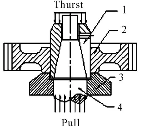
Fig.1 The basic structure ofexpansion force of the mandrel
2.2 The determination and the working principle of the motive force of the clamping
Based on the principle of the elastic centering clamping mechanism,one could know that the clamping/release of the workpiece could be achieved through the axial expanding(elastic deformation)/recovering(elastic deformation recovery)caused by the function of the external force of the mandrel or the elastic restoring force when the spring taper sleeve 1 moves up and down according to the mandrel 4.The relative up and down movement between the two elements could be the case that the spring taper sleeve 1 remains the fix while the mandrel 4 moves up and down and other reasonable cases.And the method applied in this paper is that the spring taper sleeve 1 moves up and down which mandrel 4 remains the fix,because the lower end of the mandrel needs to connect with the inner core of the machine spindle and make sure they are coaxial.The power of the up and down movement of the spring taper sleeve 1 could be the compression subject to the spring taper sleeve 1,the mechanical mechanism of that is similar as the compression between screw and the nut.Alternatively,the power could also be generated from the tension force applied reversely,such as pneumatic or hydraulic.In such case,it needs to add a system that could supply steam or air source.As this fixture is employed in the professional manufacturers who produce the gears,thereby choosing the pneumatic system generating the tension to pull the spring taper sleeve moving downwards,which means pulling down the tension rod 5 through the center of the mandrel 4 reversely to drive the spring taper sleeve moving downwards.The structure is shown in Fig.2.The spring plate of the spring taper sleeve 1 would be radial expanded to clamp the workpiece tightly under the effect of the external force from mandrel 4.When the gas pressure is eliminated,the tension will be removed.The spring taper sleeve will be tighten and moved up due to the elastic recovery while the workpiece is released.

Fig.2 Fixture preliminary design
3 Testing,setting and improvement of the fixture design
3.1 Trial processing and the analysis of the positioning precision
When the fixture was manufactured according to the preliminary design as shown in Fig.2,it was applied at the trail products processing stage.And after several times of setting and grinding,we found that how the inner core dimension of the positioning datum surface of the workpiece is close to the basic dimension.It could ensure the high precision of the radial run-out and meet the requirement of the gear end face runout.When the inner core diameter is slightly big,the radial run-out of the gear and the end surface run-out would be off the tolerance requirement.
As shown in Fig.2,when the workpiece was clamped by the expanding mandrel,the radial expansion of each point on the spring plate of the spring sleeve 1 is along the center of the processing core at the grooving root.As the expansion volume gets increased gradually along the axial from pointAto pointB,the radial clamping force used to tightening up the inner core of the workpiece will get increased gradually along pointAto pointB[3].When the inner diameter of the workpiece becomes slightly bigger(approaching to the maximum size),meanwhile the radial expanding volume < 0.5 mm when the spring sleeve in the fixture of the expanding mandrel 3 axial gets close to the axial expanding volume of pointA,the gear will generate torque momentM2resulted from the radial force of the worm wheel,which would be hard to ensure the radial run-out requirement in the gear inner core and the pitch circle and end surface run-out of the gear and its inner core.
3.2 Improvement of spring sleeve 1 and mandrel 4
How to improve expanding mandrel clamp and to enable each point in the axial direction expanding mandrel clamp spring sleeve 1 is uniform and the gap between clamping surface and workpiece positioned surface is 0.1 -0.5 mm?
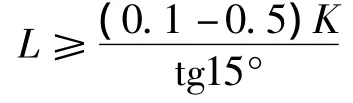

Fig.3 Grooving spring sleeve 3
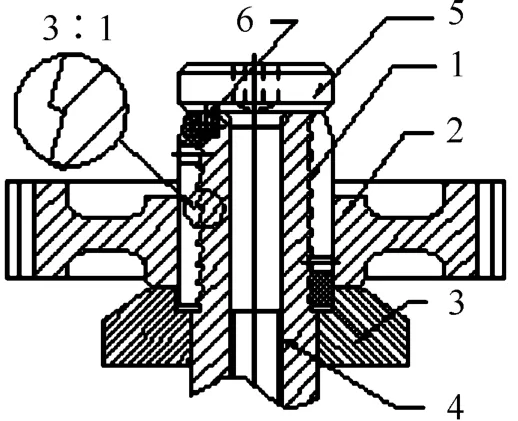
Fig.4 Improved the fixture
3.3 Estimation and analysis of clamping force
The elastic centering clamping force generated by the clamping mechanism could be calculated according to approximate formula of the clamping force of the collect chuck.If there does not exist axial positioning,the radial clamping force could be evaluated as follow[1,5]:

Where,α is spring sleeve cone angle;φ1is Spindle and spring cone suites friction angle;φ2is Workpiece and spring cone suites friction angle;Ris force consumed in the deformation of the spring;kis When the spring sleeve for six claw,k=40;Dis Spring sleeve diameter(mm);lis Spring sleeve from the slot root to the point(mm);his Average thickness of the spring sleeve(mm);Δ is Spring sleeve(not blow up)gap between the outer and the workpiece bore(mm);Qis Axial tension force(N).
Based on the approximate calculation formula,one could obtain that the desired clamping force for grinding is depend on the value ofQ(i.e.,the axial tensioning force).
4 Conclusion
Once the improved fixture was applied to the practical production,it has been confirmed that it has following merits:
1)Uniform clamping force and high precision positioning
When clamping the workpiece during the practical work,due to the improvement,the change of the each segment taper of the spring sleeve 1 along the axial is uniform under the pushing by rigid mandrel 4.Therefore,the force of clamp the inner bore of the workpiece is uniform.The use of this expanding mandrel to grinding process will have a 4-5 times higher level for the centering precision as compared to the fixture method as shown in Fig.2,which will effectively guarantee the every aspects of the precision requirement for the auto transmission gear.
2)Large clamping force and reliable clamping position
As compared with the fixture as shown in Fig.2,the thickness at the widest place of the spring sleeve 1 of this improved fixture could be reduced by one third,the number of the slot will be doubled,which would lead to largely increase of the elastic deformation in the spring sleeve of the expanding mandrel;meanwhile,the clamping force to tightening up the inner core of the workpiece will be increased to make the positioning more precision and clamping more reliable.
3)Reduce the auxiliary time,enhance the production effective
The up and down movement of the fixture as shown in Fig.3 could apply the working principle of the pneumatic(or hydraulic)cylinder to achieve the automatic clamping and releasing of the work piece.Therefore,the convenient operation will be good for the achievement of automation.It also could reduce the auxiliary time of the workpiece handling which will enhance the production effectiveness.
4)Precautions
It should be noted for the improved fixture that the matching segment taper(i.e.zigzag)of the spring sleeve 1 and mandrel 4 should use the same molding tool car during the processing to achieve the required accuracy.
[1]WENJIAN LIU,TIANHE CAO,WEIYUAN ZHAO.Fixture Engineer Manual[M].Heilongjiang Science and Technology Press,1992.
[2]ZHI XANG ZHANG Supplementary processing analysis of hydraulic cylinder of hydraulic slipway[J].Machinery,2000,27(2):21-25.
[3]LINGE SHA,YUBO ZHOU.Expanding multi-piece machining cylindrical mandrel fixture[Z].Cold Metalwork,2008 section 4.
[4]SONG WEN GAO.Expanding multi-piece machining cylindrical mandrel fixture[Z].Mechanic cold machining 2003 section 4.
[5]JINGHUA HAO.Analysis and Calculation of the automatic centering device and the clamping force of the collet[J].Tool Technology,2010(11_.
[6]JIANTIAN WANG,Application of the improved expanding mandrel[J].Metal Machining cold machining,2011(8).
