
Research on Low-cycle-fatigue Crack Propagation Life for Ship Plate Based on Accumulative Plastic Damage
2015-03-16 08:14DONGQinYANGPingDENGJunlinWANGDn
船舶力学 2015年6期
DONG Qin,YANG Ping,DENG Jun-lin,WANG Dn
(a.Depts.of Naval Architecture,Ocean and Structural Engineering,School of Transportation;b.Key Laboratory of High Performance Ship Technology of Ministry of Education,Wuhan University of Technology,Wuhan 430063,China)
0 Introduction
The fatigue strength of ship’s structure has very important significance on the safety and survivability.Along with the increasing in ship dimensions and more use of high-strength steel in recent years,the stress and deformation of ship structures are so high and large,which result in very prominent problem of low-cycle-fatigue(LCF)damage to large-scale ships.This has become the key issue demanding prompt solution in the development of large-scale ships.
Research achievements in this area are usually focused on three aspects:the accumulative damage theory,the continuum damage theory and crack propagation theory.Although the damage theory is simple,the internal stress near crack is often improperly ignored.Crack propagation theory concentrates on the relationship between stress intensity factor and crack growth rate,fatigue crack propagation is directly related to the internal stress distribution near the crack.The first proposed formula for crack growth rate was introduced by Paris et al(1961)[1]based on stress intensity factor amplitude,which predicting the fatigue crack growth rate for a variety of metal materials and non-metallic materials with good results.However,Paris formula was an empirical one,lacking the support of fatigue-crack propagation mechanism.In addition,stress intensity factor amplitude is based on linear elastic fracture mechanics,so cannot be described as the main driving force for LCF crack propagation.In 1999,Vasudevan et al[2]proposed Kmaxand△K as driving force for fatigue crack growth and took account the influence of internal stress near the crack.LCF crack propagates mainly in the plastic zone with complex stress in crack-tip.The traditional ways for fatigue-crack growth rate are based on linear elastic mechanics,so it is difficult for them to apply in the situation.To solve this problem,researchers have made a lot of research in recent years,put forward the elastic-plastic parameters of fracture mechanics similar to stress intensity factor to describe LCF crack propagation,such as crack opening displacement(CTOD)(Dover,1973)[3],plastic strain range△ε(Shimada and Furuya,1981)[4],and cyclic J integral range△J(Elhaddad and Dowling,1980)[5].These proposed parameters played a significant role in promoting the research on LCF crack propagation,but the parameters they used had some shortcomings and limitations.Crack opening displacement(CTOD)can be applied to LCF,but lacking rigorous theoretical foundation.Moreover,it is difficult to define,calculate,and measure directly,but has to rely on indirect method and experience.The plastic strain△ε used for LCF bases on the analysis of experiment results,it cannot reflect the physical mechanism of crack propagation.Because the definition of J is not clear in theory,the range△J of cyclic J integral has certain limitations for the application of LCF crack growth.Therefore,researchers set about from LCF crack propagation mechanism;established crack growth rate models suitable for LCF analysis.Fu(2010)[6]developed the LCF growth-rate prediction model based on dislocation theory and crack energy theory.Duran and Castro(2003)[7]investigated crack-propagation calculation method based on accumulative fatigue damage of strain field near the crack.The materials near the crack were divided into continuous adjacent elements,and the strain amplitude was considered as relative to fatigue life directly.By analyzing the strain distribution near the crack,the relationship between strain and fatigue life was calculated by using Coffin-Manson formula.The total damage of material was the superposition of the damage per cycle.When the damage index reaches 1,the relative element ruptures and crack propagates.Similarly,Noroozi et al(2005)[8]put forward the by-element damage analysis idea,and the stress and strain field near crack was calculated through Coffin-Manson formula and SWT(Smith-Waston-Topper)coefficient.There-after the residual stress intensity factor Krwas obtained,the relationship of da/dN-△K was established,and finally the fatigue-crack propagation life was obtained.Chen et al(Chen et al,2012;Huang et al,2011;Chen et al,2012;Shi et al,2014)[9-12]studied the crack growth behavior of structures,allowing for the mean damage of LCF and linear damage accumulation at crack tip plastic zone.
From previous studies,it has revealed that most overall fractures of ship hulls tend to be the coupling interaction result of LCF and accumulative plasticity(Huang,1996;Chen and Liu,2006)[13-14].The actual ship hull structures under service loading may suffer from fatigue damage,and the accumulative plastic deformation exceed a certain limit,thus cracks may initiate and propagate until structure failure.Therefore,the LCF crack propagation analysis and estimation based on the accumulated incremental plastic damage can predict the fatigue strength of ship hull structures more reasonably and realistically.
In viewpoint of these,based on the cyclic stress-strain field of a fatigue crack tip,a fatigue damage parameter from the strain amplitude is presented in the paper.By introducing a correction term that contains accumulative plastic strain rate to reflect the influence of accumulative plasticity on fatigue life under asymmetrical cyclic loading,a new LCF crack-growth prediction model is established,which considers the effect of accumulative plasticity inside the plastic zone at the crack tip.
1 LCF crack growth prediction model allowing for accumulative plasticity
1.1 Description of cyclic stress-strain field near crack tip
The stress concentration at crack tip due to high stress may cause material yield around the local zone,therefore the material near crack tip can be divided into elastic zone and plastic zone,as shown in Fig.1.In the plastic zone,the stress field can be subdivided into two zones:the monotonic plastic zone corresponding to the maximum stress intensity factor Kmax,and the cyclic plastic zone corresponding to stress intensity factor amplitude△K.The size of these two zones is(Castro et al,2005)[15]:

where rcis cyclic plastic zone size,rmis monotonic plastic zone size,σyc′is cyclic yield stress,n′is cyclic hardening exponent,κ=1(for plane stress);.

Fig.1 Plastic zones at front of crack tip
Since the material at crack tip is located in different stress zone,the stress field can be expressed by elastic form,plastic form.Generally,the Westergaard stress distribution function(Westergarrd,1939)[16]based on linear elastic fracture mechanics is adopted;the stress-strain field near the crack tip based on the Hutchinson-Rice-Rosengren(HRR)(Schwable,1974)[17]field is adopted.The linear elastic stress field near crack tip under plane stress state is as follows:

where△K is stress intensity factor amplitude,E is elastic modulus,r is the distance of a node from the crack tip,r0is blunting radius of crack tip,△σeis elastic stress amplitude,△εeis elastic strain amplitude.
For the plastic stress field near crack tip and in plane-stress state,considering the blunting phenomenon at crack tip during crack propagation,the stress-strain field near the crack tip can be obtained by interpolation method as follows:
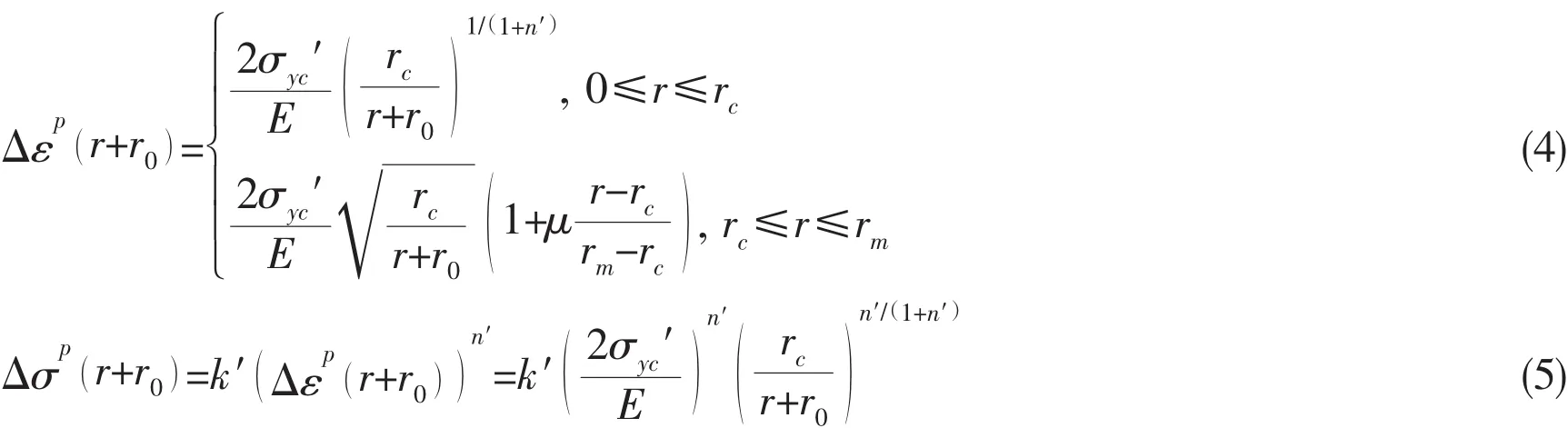
where k′is cyclic hardening coefficient.
According to Rice’s assumptions,blunting radius r0is equal to half of the crack tip opening displacement(CTOD)and can be expressed as(Schwable,1973)[18]:

The plastic zone is composed of monotonic plastic zone and cyclic plastic zone.When stress ratio R≥0,then rm≥rc.According to the finite element analysis result,the following assumptions can be made in the paper:
(1)σ,ε are plastic in cyclic plastic zone.△σ,△ε are elastic and can be determined by Eqs.(2-3).
(2)σ,ε,△σ,△ε are all plastic outside of monotonic plastic zone,and △σ,△ε can be determined by Eqs.(2-3).
(3)σ,ε,△σ,△ε are elastic-plastic coexistence between monotonic plastic zone and cyclic plastic zone,and △σ,△ε can be obtained by nonlinear interpolation function.
1.2 LCF critical damage
Engineering components subjected to non-zero mean stress asymmetrical cyclic loading would be likely to produce accumulative plastic deformation.The accumulative plastic strain may cause additional damage that will shorten fatigue life.Therefore,estimating the fatigue life of components under asymmetrical cyclic loading should consider both of accumulative plastic damage and fatigue damage,and the interaction between them.In this paper,it is assumed that the total damage in LCF is composed of two parts,namely LCF damage Dfand accumulative plastic damage Dr,so we have:

where Dfreflects fatigue damage which does not consider accumulative plastic strain,Drreflects additional damage caused by accumulative plastic strain.
According to linear accumulative damage theory,we have:

where Nfis failure cyclic number controlled by LCF,Nris failure cyclic number controlled by accumulative plastic strain.
In order to establish the relationship between stress,strain and fatigue life,Manson-Coffin model can be used to describe uniaxial LCF behavior of components:

According to the fatigue theory,the fatigue life can be obtained by substituting △εe,△εpinto Eq.(9).Because elastic deformation is small in plastic zone,so the elastic strain can be omitted in the actual calculation,so we have:

The accumulative plastic strain will cause additional damage.In the stress-control cycle,for the non-zero mean stress asymmetrical cyclic loading,the failure cycle number controlled by accumulative plastic strain can be calculated by prediction model proposed by Xia(Xia et al,1996)[19],which taking account of the influence of accumulative plastic strain.
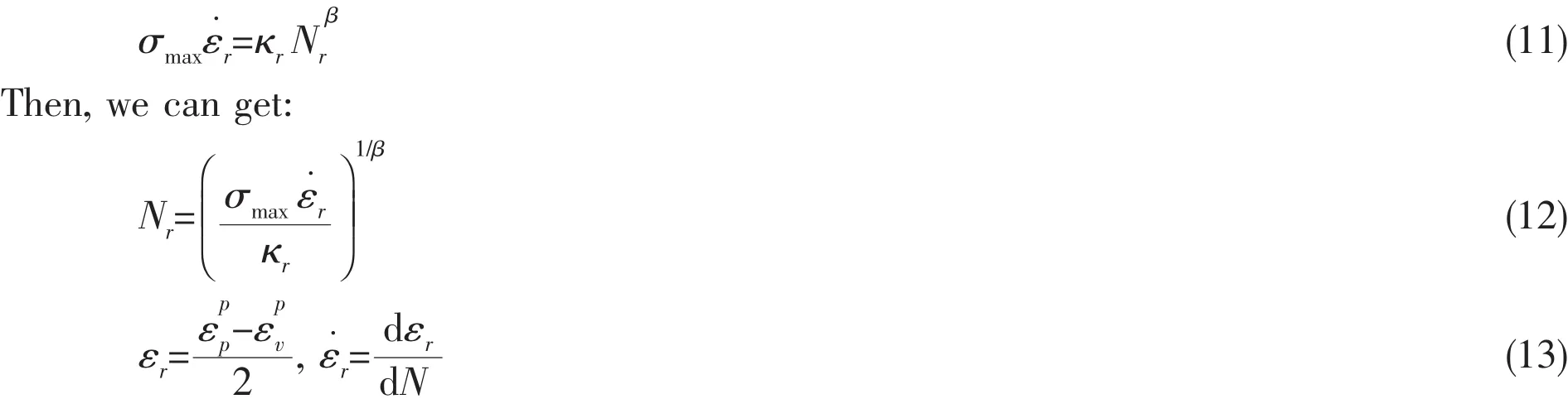
where κr, β are material parameters,is accumulative plastic strain rate in the process of steady accumulative plastic-strain development,represent the true plastic strain in the peak and valley cyclic loading,respectively.
Hence,the fatigue damage parameter allowing for the effect of accumulative plastic strain is:

The existing researches show that the cracked plate is composed of a series of fatigue units as shown in Fig.2.It is assumed that every cyclic loading causes unit damage.Defining unit damage Di=1/Ni,after n cyclic loadings,the total unit damage is:


Fig.2 The material unit model at front of crack-tip
According to the Miner accumulative damage theory,the crack will grow δa when D=1.Therefore,the accumulative damage of the unit near crack tip under cyclic loading can be calculated.
1.3 The fatigue crack growth prediction model
According to the fatigue discontinuous phenomenon of fatigue crack propagation,assume that each step of the crack advancement size equals to the plastic zone size along the crack growth direction(Hurley and Evans,2007)[20].Defining the average damage of unit along the crack growth direction in the plastic zone:

Then the new crack-growth prediction model allowing for the influence of accumulative plastic strain is expressed as:
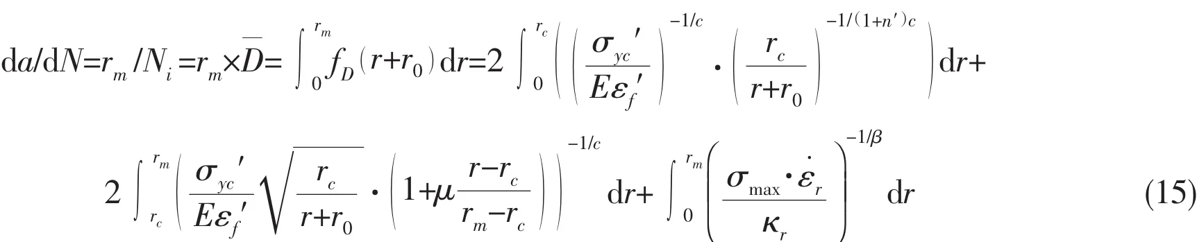
From Eq.(15),it is found that the crack growth rate under cyclic loading depends on the size of fatigue propagation zone.The larger size of fatigue propagation zone is,the faster crack-growth rate will be,and vice versa.Hence,the key to enhance the accuracy of prediction model is to determine appropriate fatigue propagation size.
2 Example calculation and analysis
In order to verify the feasibility of the crackgrowth prediction model proposed in this paper,the plate with crack made of 304 stainless steel(Chen and Cai,2012)[21]is employed to analyze LCF crack propagation.According to the axis-symmetric characteristics of the rectangular plate,only half of the plate is set up for finite element model.The planestress element PLANE82 of ANSYS is used to improve computational efficiency.Taking into account the singularity at crack tip,quadratic singular element is applied,and refined mesh is used for the crack tip region to ensure simulation accuracy.Stress ratios R=0.1,R=0.2 are applied to the model boundary from the fatigue-crack propagation test conditions.Chacoche constitutive model is used to simulate material and von-Mises yield criterion is applied.The geometry and the finite element model of the plate with crack are shown in Fig.3 and the basic mechanics properties of 304 stainless steel are listed in Tab.1.

Fig.3 Geometry and finite element model of ship plate with crack

Tab.1 Material parameters of 304 stainless steel
2.1 Stress-strain curve of plate with crack under cyclic loading
Under the asymmetrical stress cyclic loading,Chacoche nonlinear kinematic hardening model is adopted for numerical analysis of the plate with crack by ANSYS.Selecting the node at crack tip,the stress-strain response near crack tip under asymmetrical stress cyclic loading is obtained as shown in Fig.4.
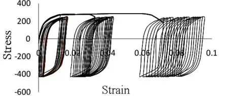
Fig.4 The stress-strain curve near the crack tip of Chaboche cyclic plastic model
It can be seen from Fig.4 that the plate with crack generates accumulative plastic strain under asymmetrical stress cyclic loading.In the initial cycle,the accumulative plastic strain grows relatively slow.With the increasing of cyclic number,the accumulative plastic strain rate increases gradually and tends to stable.
2.2 The relationship between cycle numbers and accumulative plastic strain for plate with crack
The plate with crack is the same as shown in Fig.3.For the two different stress ratios,the relationships between accumulative plastic strain and recycle numbers are obtained as shown in Fig.5.
It can be seen from Fig.5,the accumulative plastic strain at crack tip increases gradually with the increasing of cycle numbers under different stress ratio of cyclic loading.The accumulative plastic strain is larger corresponding to greater stress ratio.While,with the increase of cycle numbers,the accumulative plastic strain tends to stable.The finite element results show that stress ratio has significant effect on accumulative plastic strain for plate with crack.

Fig.5 The relationship between cycle numbers and accumulative plastic strain for ship plate with crack
2.3 The LCF growth rate of plate with crack
Combining the mechanical properties and LCF performance parameters of 304 stainless steel obtained by tests,and adopting the LCF crack-growth prediction model by Eq.15,the paper forecasts the crack propagation behavior of the plate with crack.In the mean while,finite element analysis is carried out to predict crack growth rate.The results by the theoretical analysis,finite element method,and experimental tests from the reference are shown in Fig.6.
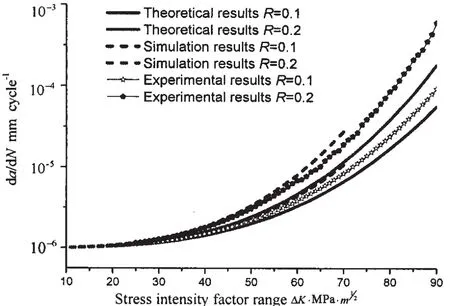
Fig.6 The curves of LCF crack growth rate of plate with crack under different stress ratio
It can be found from Fig.6,the experimental tests are consistent with prediction results,and show smaller dispersion.It indicates the prediction model can well reflect the LCF crack propagation behavior of plate with crack.The LCF crack-growth prediction model proposed in this paper shows certain feasibility and good precision.
From the study of the paper,it is shown that the finite element method can only predict the former part of crack-growth rate curve.The step-length adopted in the finite element method is proper only for plastic zone around crack tip under monotonic loading condition,which is different from the plastic zone at crack tip under cyclic strain fatigue condition.Therefore,the prediction results from FEM show a difference from experimental result,and the prediction range is limited.This is because of the effects from mesh quality and algorithm,among others.FEM calculations not only give rise to error but also may stop processing when the crack size or the load is too large to lead mesh distortion.Therefore,the FEM cannot correctly predict fatigue crack growth rate for a wide range.While,the theoretical model of the paper relies on the plastic zone at crack tip,adopts the actual cyclic plastic strain,and considers the influence of accumulative plastic strain increment,hence,the new model has higher precision and a wider range of prediction.
3 Conclusions
By introducing a correction term that contains accumulative plastic strain rate to reflect the influence of accumulative plasticity on fatigue life under asymmetrical cyclic loading,a new LCF crack-growth prediction model inside the plastic zone at the crack tip is established.A fatigue damage parameter of the strain amplitude is defined based on the cyclic stress-strain field of a fatigue crack tip.The model considers the effect of accumulative plasticity.The conclusions and outlooks can be drawn from the result as follows:
(1)Based on the cyclic stress-strain field around fatigue crack tip,by introducing the accumulative plastic strain rate,a new LCF crack-growth rate prediction model in plastic zone is obtained.All the parameters in the new model have definite physical meanings without any artificial adapting.
(2)The predictions of the LCF crack-growth behavior of plate with crack from the new model and FEM are consistent with the experimental results.It is suggested that the LCF crack-growth rate prediction method is feasible to allow for the influence of accumulative plasticity.By contrast,to some extent,the new theoretical model has broader predictability and simplicity than FEM.
(3)With the increasing of cyclic number,the generated accumulative plastic strain will increase the LCF crack growth rate of plate with crack.Moreover,the larger the accumulative plastic strain is,the greater the crack growth rate will be,which reveals that analyze the LCF crack-growth rate of plate should consider the effect of accumulative plastic strain.
(4)In order to achieve a more comprehensive and reasonable prediction model,the stress damage may be introduced to increase the accuracy.In addition,the presented model ignores the distribution of the cyclic stress and strain amplitudes along the thickness direction of the plate,which may be dealt with as the three-dimensional fracture problem.Therefore,when it is expanded to the three-dimensional problem,the equivalent fatigue analysis will be very complicated to deal with.
[1]Paris P C,Gomez M P,Anderson W P.A rational analytic theory of fatigue[J].The Trend in Engineering,1961(13):9-14.
[2]Sadananda K,Vasudevan A K,Holtz R L,Lee E U.Analysis of overload effects and related phenomena[J].International Journal of Fatigue,1999(21):S233-S246.
[3]Dover W D.Fatigue crack growth under COD cycling[J].Engineering Fracture Mechanics,1973(50):11-21.
[4]Shimada H,Furuya Y.Application of crack tip strain loop to fatigue crack propagation[J].Experimental Mechanics,1981(21):423-428.
[5]Elhaddad M H,Dowling N E,Topper T H.Integral application for short fatigue cracks at notch[J].International Journal of Fracture,1980,16(1):15-30.
[6]Fu H.Study of the characteristics of fatigue crack propagation based on dislocation theory[D].Changsha:Changsha University of Technology,2010.
[7]Duran J A R,Castro J T P.Fatigue crack propagation prediction by cyclic plasticity damage accumulation models[J].Fatigue&Fracture of Engineering Materials&Structures,2003(26):137-150.
[8]Noroozi A H,Glinka G,Lambert S.A two-parameter driving force for fatigue crack growth analysis[J].International Journal of Fatigue,2005,27:1277-1296.
[9]Chen L,Cai L X.The low cyclic fatigue crack growth prediction model based on material’s low cyclic fatigue properties[J].Engineering Mechanics,2012,29(10):34-39.
[10]Huang X W,Cai L X,Bao C,Chen L.A new method of numerical simulation for behavior of fatigue crack propagation based on low cycle fatigue damage[J].Engineering Mechanics,2011,28(10):202-208.
[11]Chen L,Cai L X,Yao D.Prediction model of fatigue crack growth behavior by introducing strain cycle damage[J].Journal of Xi’an Jiaotong University,2012,46(9):114-118.
[12]Shi K K,Cai L X,Chen L,Wu S C,Bao C.Prediction of fatigue crack growth based on low cycle fatigue properties[J].International Journal of Fatigue,2014(61):220-225.
[13]Huang Z Q.A new insight of ship’s longitudinal strength criterion[J].China Shipbuilding,1996(3):87-98.
[14]Chen G,Liu Y H.Numerical theories and engineering methods for structural limit and shakedown analyses[M].Beijing:Science Press,2006.
[15]Castro J T P,Meggiolaro M A,Miranda A C O.Singular and non-singular approaches for predicting fatigue crack growth behavior[J].International Journal of Fatigue,2005,27:1366-1388.
[16]Westergarrd H M.Bearing pressures and cracks[J].Journal of Applied Mechanics,1939,6:A49-A53.
[17]Schwable K H.Comparison of several fatigue crack propagation laws with experimental results[J].Engineering Fracture Mechanics,1974,6(2):325-341.
[18]Schwable K H.Approximate calculation of fatigue crack growth[J].Journal of Engineering Fracture,1973,9:381-395.
[19]Xia Z,Kujawski D,Ellyin F.Effect of mean stress and ratcheting strain on fatigue life of steel[J].International Journal of Fatigue,1996,18(5):335-341.
[20]Hurley P J,Evans W J.A new method for predicting fatigue crack propagation rates[J].Materials Science and Engineering A,2007,466(1/2):265-273.
[21]Chen L,Cai L X.Research on fatigue crack growth behavior of materials by considering the fatigue damage near the crack tip[J].Journal of Mechanical Engineering,2012,48(20):51-56.