
Magnetometer calibration algorithm based on ellipsoid constraint①
2015-04-17 07:24DongMingjie董明杰
High Technology Letters 2015年4期
Dong Mingjie (董明杰
(Robotics Institute, Beijing University of Aeronautics and Astronautics, Beijing 100191, P.R.China)
Magnetometer calibration algorithm based on ellipsoid constraint①
Dong Mingjie (董明杰②
(Robotics Institute, Beijing University of Aeronautics and Astronautics, Beijing 100191, P.R.China)
Calibration of magnetometer is an essential part to obtain high measurement precision. However, the existing calibration methods are basically the calibration of all attitudes, which means tough work when the magnetometer is applied in strapdown inertial navigation system (SINS). So a quick, easy and effective calibration algorithm is developed based on the ellipsoid constraint to calibrate magnetometers. In this paper, the measuring principle and error characteristic of the magnetometer are analysed to study its magnetic interference. During the process, a magnetometer calibration model is set up to convert the calibration to ellipsoid fitting based on the characteristic of hard magnetic interference and soft magnetic interference. Then the algorithm is tested by mimic experiment. The result shows that measurement precision is improved after the calibration, and then the magnetometer is installed in a control cabin of an underwater robot which is designed and developed by us, and actual magnetometer calibration experiments are conducted to further verify the validity of the algorithm.
calibration, magnetometer, ellipsoid constraint, strapdown inertial navigation system (SINS)
0 Introduction
Magnetometer is widely used in the navigation system. It measures the geomagnetic information by its sensitive ness to the magnetic fields. It is low in cost and small in size, and meanwhile, it is easy to be integrated. Magnetometer is often used to form a small attitude measurement unit with other sensors, such as accelerometer and gyroscope, to measure the direction. Nowadays, it has become an important composition of the attitude measurement unit, and is widely used in unmanned aerial vehicle, mobile robot, submarine and satellite, etc. However, it is easy for the local geomagnetic field to produce distortion for being affected by external magnetic field, which can result in the error between the measured direction and the actual geographical direction. Of course, the installation structure of the magnetometer and different electronic circuits can also result in the error. Therefore, it is very necessary to calibrate the magnetometer before using it to improve its precision[1-4].
Many people have researched the problem in academia. Some scholars use EKF (extended Kalman filter) to estimate the zero bias and the calibration factors of the magnetometers[5], and propose the UKF (unscented Kalman filter) method for magnetometer calibration[6]. By comparing with the EKF method, it comes to the conclusion that the UKF is more efficient. Some academics have done a lot of research work on the calibration of the alignment error of the magnetometer, the calibration factor error of the soft magnetic interference and the zero offset of the hard magnetic interference using the improved two-step estimation algorithm, and the validity of the algorithm is verified in a small UAV (unmanned aerial vehicle)[7]. Some academic researches on the error correction of the three-axis magnetometer utilizing the neural network algorithm[8], the precision of the magnetometer after calibration is improved. However, the parameters obtained through neural network training are easy to spread under different environmental samples. Some academics calibrate the magnetometer using the constrained least squares algorithm given the feature that the interference magnetometer measurements can be simplified into the ellipse[9]. The MTi products of the Xsens Company on the market are also using the least squares method to calibrate the magnetometers at present[10]. However, the existing calibration methods are basically the calibration of all attitudes[11-14], which means tough work when the magnetometer is applied in SINS. So it is of very practical significance to suggest a quick, easy and effective calibration algorithm. Given the idea, a calibration algorithm is prosed to calibrate hard magnetic interference and soft magnetic interference of the magnetometer based on the ellipsoid constraint. In this paper, the measuring principle and error characteristic of the magnetometer are analysed, and the calibration algorithm is proposed based on ellipsoid constraint. Finally the algorithm through mimic and actual experiments is tested and verify the validity of the algorithm is verified.
1 Principle and error analysis of magnetometer
1.1 Measurment Principle of the Magnetometer
The magnetometer works through induction of the geomagnetic field. The geomagnetic field is a vector field, and its intensity can be decomposed into three components, the north, the east and the vertically downward direction.
It is assumed that the magnetic field intensity in the horizontal plane projection is H, and there is an angle between H and geographical north direction, which is called magnetic declination and indicated by the letter shown in Fig.1. Therefore the north-south direction of the compass points is the geomagnetic north and south, which has a deviation with the geographic north and south direction, the deviation is called magnetic deviation. The magnetic heading is defined as the angle between the horizontal plane projections of the carrier’s vertical axis with the local magnetic meridian when the magnetometer works on the carrier. The three-axis magnetometer measures the components of the longitudinal axis, transverse axis, and vertical axis to be Hx, Hyand Hzrespectively. Hence, the projections of the geomagnetic intensity on the geographical coordinate system and the carrier coordinate system can be presented by the transformation matrix between the two coordinates.

(1)
where, H0is the horizontal component of the magnetic field, α is magnetic inclination, ψ is yaw angle, θ is pitch angle, γ is roll angle. The angle calculation formula is got:

(2)
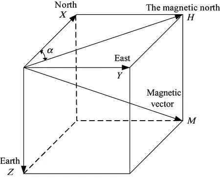
Fig.1 Magnetometer measurement model
1.2 Error Analysis of the Magnetometer
There are many measurement errors during the process of the magnetometer measurement, generally divided into manufacturing error, installation error, attitude signal error and compass deviation. The manufacturing error is related to many factors, mainly manifests in three aspects. The first is the zero error which is caused for the reason that the zero point of the sensor, analog circuit and A/D converter is not zero. The second is the sensitivity error caused by different sensor sensitivities. The third is orthogonal error, which is caused for the reason that the three sensor measuring axes cannot be mutually perpendicular completely during the manufacturing process. The installation error is caused for the reason that we cannot guarantee that the three axes of the sensor are parallel to the longitudinal, transverse and vertical axis of the carrier respectively. The attitude signal error is due to the signal error of the pitch angle and the inclination angle. Although it does not belong to the magnetic heading system, it can result in the heading error when it is involved in the navigation position calculating. Compass deviation is due to the influence of the ferromagnetic materials around the magnetic sensor. It is a specific error during the heading measurement using geomagnetic field, which can be divided into the hard magnetic material interference error and the soft material interference error. Soft magnetic materials get magnetism after magnetized by the magnetic field for it has no magnetism itself. And its magnetism varies along with the variation of the strength and the relative direction of the geomagnetic field. The direction of the force of the soft magnetic material on the magnetometer is related to the mutual position between the soft iron and the magnetometer, and its strength is related to soft iron material, soft iron attitude, the exciting magnetic field and the distance between the soft iron and the magnetometer. The hard magnetic material is the permanent magnet on the carrier, whose strength and direction are fixed and has no change along with the course and the latitude. The hard iron on the carrier is from DC (direct current), permanent magnet and the motor, etc. Thus it is apparent that calibration is an essential procedure in order to measure precision of the magnetometer.
The magnetometer calibration can be divided into the factory calibration and the field calibration. There can be non-orthogonal error and installation error during the installation of the three-axis magnetometer. Meanwhile, there can also be zero deviation and calibration factor error due to the manufacturing factors. All these errors need software compensation through the factory calibration. The field calibration is to reduce the effects the carrier and surrounding magnetic field have on the magnetometer, and to improve its measurement precision. For the magnetometer parameter obtained by the factory calibration is stable, and the magnetic properties are not the same when magnetometer is used in a different environment, it is very necessary to compensate various magnetic interferences through the field calibration.
2 Field calibration algorithm
2.1 Calibration model
The main consideration of the field calibration is the hard magnetic interference and the soft magnetic interference the magnetometer gets from the field environment. The hard magnetic material on the carrier is equivalent to a permanent magnet, whose strength is a vector with fixed magnitude and direction. There may be many hard magnetic materials around the sensors with different magnetic strength and direction. But the projection component of the synthetic magnetic field from these hard magnetic materials on the three-axis magnetic sensor is the same regardless of the changes of the carrier attitude, for the sensors and the hard magnetic materials are all fixed on the carrier. In other word, the error caused by the hard magnetic material interference is a constant error. Unlike the hard magnetic material, the soft magnetic material doses not produce magnetic field. But it will influence the magnetic field around it after being magnetized, and the strength and direction it influences is related to the environment magnetic field and the property of the soft magnetic material. From the electromagnetism knowledge, ferromagnetic material can be magnetized to produce magnetic moment under the action of external magnetic field, and the vector sum of the magnetic moment per unit volume is the magnetization strength vector, whose magnetic moment strength is proportional to the strength of the external magnetic field. For paramagnetic, the direction of the magnetic moment is to the external magnetic field, while for diamagnetic, the direction is to the opposite direction of the external magnetic field. Therefore, the inductive magnetic field of the carrier is not only related to the strength of the external magnetic field, but also related to the direction of the external magnetic field. To sum up, the relationship between the real value of the geomagnetic field and the measurement value from the magnetic sensor can be expressed as

(3)
where, H is the magnetic vector, the direction of the geomagnetic field somewhere on the earth usually can be obtained from sea chart or map, and it can be regarded as uniform in a certain range. The letter is the constant deviation caused by hard magnetic material interference, that is the measurement noise of the magnetometer, and the letter is the calibration factor matrix of the soft magnetic interference field, and its value can be described as
(4)
where, βijis the induction coefficient of soft magnetic interference of field, i and j indicates x, y, z, βijrepresents the induced magnetic field component of the i direction of the carrier on the jth direction of the magnetic sensors, in other words, it means the increasing or decreasing coefficient of the magnetic field strength in the ith direction for the reason of the soft magnetic interference.
2.2 Field calibration algorithm
For the state of the interference magnetic field at some point, a hypothesis is widely used now. That is, the vertex of the total geomagnetic field can draw a sphere with the variation of the sensor attitude in the condition without interference magnetic field. For a carrier with its attitude all-round changes, when there is hard magnetic effect, the interference is equivalent to adding a fixed value on the measurement of the sensor, which can create a bias of the sphere model with the original offset. However, when there is soft magnetic effect, the deformation of the sphere model occurs and can be approximate to an ellipsoid, for the strength of the induced magnetic field is different under different attitude. Namely the effect the induced magnetic field has on the geomagnetic measurement can be thought as an ellipsoid which is drawn by the synthetic vector vertex with the three components the sensor measures, shown in Fig.2.

Fig.2 Measurement with external magnetic interference
According to the above content, Eq.(3) can be rewritten as

(5)
(6)
Eq.(5) can be thought as an elliptic equation, namely the measurement of the magnetometer is in an ellipsoid, and therefore, the field calibration algorithm of the magnetometer is put forward based on ellipsoid constraint. Eq.(5) can be expanded as

(7)
which is the coefficient of the matrix.
(8)
Here, Eq.(7) can be further written in a matrix form,

(9)
where, the vector can be defined as:
(10)
If vector p is already known, then the correlation coefficient aijcan be got according to the corresponding relation of elements in Eq.(10).


(11)
(12)
(13)
Eq.(13) can be simplified as a matrix form:
(14)
Value p can be estimated by the least squares algorithm:
(15)

3 Simulation and field experiment
3.1 Simulation
At first, simulation is used to verify the algorithm. It is assumed that the ideal measurement value of the three-axis magnetometer is on the unit sphere, the parameter change caused by the hard magnetic interference is b, and the parameter change caused by the soft magnetic interference is A after the field magnetic interference.
(16)
At the same time, the noise with its variance value 0.05 is superimposed on the measurement value. Zhen we carries on the simulation, the result of the ideal situation compared with the interference situation is shown in Fig.3

Fig.3 Comparison between measured and ideal value before calibration
After that, the proposed algorithm based on the ellipsoid constraint is used to calibrate the magnetometer, the parameters is

(17)
The measurement value after calibration is very close to the ideal value, shown in Fig.4

Fig.4 Comparison between measured and ideal value after calibration
3.2 Field calibration experiment and the results
Our experiment platform is an underwater robot designed by our laboratory. At first, IMU (inertial measurement unit) is installed with magnetometer (Fig.5) in the control cabin of the underwater robot (Fig.6), and then the data of the magnetometer can be collected. As we all know, the magnetometer needs to be rotated by 360 degrees around the three-axis direction in the process of calibrating the magnetometer using traditional calibration algorithm, especially, the magnetometer needs to be kept in the three orthogonal planes during the rotation, which may be easy to calibrate a single magnetometer, but it is not convenient to conduct the calibration experiment for the whole underwater robot. Yet such calibration operation requirements are not needed using the ellipsoid constraint algorithm, all we need to do is to collect the data of 3-D attitude rotating part. The calibration process is simple and the efficiency of calibration is raised, as shown in Fig.7.

Fig.5 IMU with magnetometer

Fig.6 Underwater robot

Fig.7 3-D data of field calibration
The data of the three-axis magnetometer obtained before calibration is shown in Fig.8

Fig.8 Field measurement data before calibration
Then the magnetometer is calibrated, and the results got through the calibration algorithm is as

(18)
The data of the three-axis magnetometer obtained after calibration is shown in Fig.9.
In order to see more intuitively, the magnetic strength data before calibration is compared with the data after calibration, as shown in Fig.10
From Fig.10, it can been seen that the measurement value after calibration of the magnetometer is improved dramatically.

Fig.9 Field measurement data after calibration

Fig.10 Strength value comparison before and after calibration
4 Conclusions
In this paper, a quick, easy and effective algorithm is introduced to calibrate the magnetometer based on ellipsoid constraint. After analyzing the measuring principle and error characteristic, the calibration problem to ellipsoid fitting problem is coverted based on the characteristic of the hard magnetic interference and the soft magnetic interference, and the calibration algorithm is proposed based on the ellipsoid constraint. After simulation and actual field experiment with the underwater robot, the validity of the algorithm is verified. Compared with the traditional calibration algorithm, this algorithm is much easier, and more suitable for application in SINS. It can not only improve the calibration efficiency, but also improve the measurement precision of the magnetometer.
[ 1] Dorveaux E, Vissière D, Martin A P, et al. Iterative calibration method for inertial and magnetic sensors. In: Proceedings of the Joint 48th IEEE Conference on Decision and Control and 28th Chinese Control Conference, Shanghai, China, 2009. 8296-8303
[ 2] Genovese V, Sabatini A M. Differential compassing helps human-robot teams navigate in magnetically disturbed environments. IEEE Sensors,2006,6(5):1045-1046
[ 3] Bijker J, Steyn W. Kalman filter configurations for a low-cost loosely integrated inertial navigation system on an airship.Control Engineering Practice, 2008,16(12):1509-1518
[ 4] Lyon D H. A military perpective on small unmanned aerial vehicles. IEEE Instrum entation and Measurement Magazine, 2008,7(3):27-31
[ 5] Guo P, Qiu H, Yang Y. The soft iron and hard iron calibration method using extended Kalman filter for attitude and heading reference system. In: Proceedings of the IEEE Position Location Navigation Symposium, Monterey, USA, 2008. 1167-1174
[ 6] Crassidis J L, Lai K L, Harman R R. Real-time-attitude-independent three-axis magnetometer calibration. Journal of Guidance, control and dynamics, 2005, 28(1): 115-120
[ 7] Wu Y L, Wang T M, Liang J H. In-suit error calibration of three-axis magnetometer for unmanned aerial vehicle. Acta Aeronautica et Astronautica Sinica,2011, 32(2):330-336
[ 8] Wu D H, Huang S L, Zhao W. Research on correction of tri-axial magnetometer based on FLANN. Chinese Journal o f Scientific Instrument, 2009,30(3):449 -453 (In Chinese)
[ 9] Fang J C, Sun H W, Cao J J, et al. A novel calibration method of magnetic compass based on ellipsoid fitting. IEEE Transactions on Instrumentation and Measurement, 2011, 60(6): 2053-2061
[10] Xsens Technologies, Available. http://www.xsens.com: Xsens, 2014
[11] Koo W, Sung S, Lee Y J. Error calibration of magnetometer using nonlinear integrated filter model with inertial sensors. IEEE Transactions on Magnetic, 2009,45(6):2740-2743
[12] Egziabher D G, Elkaim G H, Powell J D, et al. Calibration of strapdown magnetometers in magnetic field domain. Journal of Aerospace Engineering,2006,19(2):87-102
[13] Foster C C, Elkaim G H. Extension of a two-step calibration methodology to include nonorthogonal sensor axes. IEEE Transactions on Aerospace and Electronic Systems, 2008,44(3):1070-1078
[14] Jurman D, Jankovec M, Kamnik R, et al. Calibration and data fusion solution for the miniature attitude and heading reference system. Sensors and Actuators A, Physical, 2007,138(2):411-420
Dong Mingjie, born in 1989, he is pursuing the Ph.D. degree in the Mechatronic Engineering in Beijing University of Aeronautics and Astronautics. He received the Bachelor degree in Material Forming and Control Engineering from Beijing University of Aeronautics and Astronautics in 2012. His research interests include embedded electronmechanical control and control of robot.
10.3772/j.issn.1006-6748.2015.04.005
①Supported by the National High Technology Research and Development Programme of China (No. 2011AA04201).
②To whom correspondence should be addressed. E-mail: dongmj@buaa.edu.cn Received on May 17, 2014, Chou Wusheng, Fang Bin
 High Technology Letters2015年4期
- High Technology Letters的其它文章
- Motion mechanism analysis of two contacting rollers①
- Two-stage DOA estimation method for passive radar based on sparse representation①
- Study and application of vibrating wire strain gauge in monitoring cable tension of FAST cable-net①
- Service optimization in programmable cloud network①
- Design of bilayer lengthened LDPC codes over expanded graph for relay channels①
- Effect of laser heating on the microstructure and hardness of TRIP590 advanced high strength steel used for roll forming①