
Transient dynamic analysis and comparison on wedging processes of overrunning clutches with different contact surfaces
2015-04-22 06:17WEIWei魏巍ZHOUQia周洽LIUShucheng刘树成YANQingdong闫清东
关键词:魏巍
WEI Wei(魏巍), ZHOU Qia(周洽), LIU Shu-cheng(刘树成) ,YAN Qing-dong(闫清东)
(School of Mechanical Engineering, Beijing Institute of Technology, Beijing 100081, China)
Transient dynamic analysis and comparison on wedging processes of overrunning clutches with different contact surfaces
WEI Wei(魏巍), ZHOU Qia(周洽), LIU Shu-cheng(刘树成) ,YAN Qing-dong(闫清东)
(School of Mechanical Engineering, Beijing Institute of Technology, Beijing 100081, China)
The effects of contact surface on dynamic wedging behavior of the roller and inner-ring of the overrunning clutch in a dual-turbine torque converter were investigated to reveal the friction self-locking mechanism and dynamic process. Planar strain clutch models including roller, inner-ring and outer-ring were built, and transient wedging process was analyzed with an explicit dynamics method. The modeling of stress and strain distribution and variation of two kinds of contact surfaces show that there are three stages named slipping, wedging and binding respectively during whole wedging process. Meanwhile the geometric structures of contact surfaces greatly influence the peak stress and strain distribution of the wedging process of the roller and inner-ring. The load bearing performance of contact surfaces with logarithmic spiral curve is better than that with straight line. Our study provides theoretical foundation for design and further optimization of wedging contact surface of an overrunning clutch in a dual-turbine hydrodynamic torque converter.
overrunning clutch; wedging process; explicit dynamics; torque converter
In order to widen the high efficiency range and improve the stall torque performance of the hydrodynamic components of an engineering vehicle, a dual-turbine hydrodynamic torque converter (DTHTC) is adopted. A DTHTC has two working regions, the low and high speed ration regions. Two turbines work during the low speed ratio region, while a single turbine works during the high speed ratio region. The conversion between the two work conditions is realized by an overrunning clutch, so that the synthesized performance can be improved.
Researches on overrunning clutches in hydrodynamic transmission technology mainly focus on clutches mounted on typical integrated torque converters (i.e., torque converter-coupling), whose inner rings are fixed while outer rings are connected to stator[1-2]. When working fluid imposed loads on the outer ring, the dynamic analysis on the wedging process of this kind of structure is relatively convenient since only one part is rotating and the other is still. However for a DTHTC, two parts of the clutch (connected to first turbine and second turbine, shown in Fig.1) are all rotating, even at different speeds[3], which leads to difficulty for wedging process analysis because the rotating speed trends of the two turbines are hard to be ascertained simultaneously during the wedging process measured in millisecond level[4-6].
In this paper, planar strain finite element analysis of two different contact surfaces of an overrunning clutch in a DTHTC was conducted based on the explicit dynamics analysis. The corresponding wedging process characteristics of the overrunning clutch in a DTHTC was investigated.

Fig.1 Layout of overrunning clutch in DTHTC
1 Computational models with different contact surfaces
An overrunning clutch comprises three parts: outer ring, inner ring and rollers (Fig.2). It has a cyclosymmetric structure and can be divided into 20 equivalent parts[7].
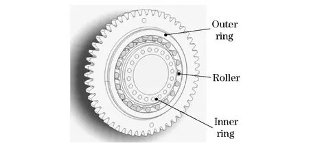
Fig.2 Structure of an overrunning clutch
The axial length of the clutch is much larger than the radial length. The external forces are vertical to the axial direction of the clutch and assumed to remain constant along the length. Therefore, the dynamic computational model of wedging process can be established as 2D plane stain finite element model, and 1/20 of the overrunning clutch is extracted due to its cyclosymmetric structure. Fig.3a shows a linear contact surface with straight line, and Fig.3b shows a surface with logarithmic spiral curve.

Fig.3 1/20 model of overrunning clutches with two different contact surfaces
By considering calculation efficiency and precision simultaneously, meshes of element PLANE162 in computation models shown in Fig.3 were denser near contact area and coarser in non-contact area.
2 Boundary condition and loads setting
In layout of a DTHTC, the outer ring of an overrunning clutch is connected to the first turbine and the inner ring is connected to the second turbine by gear pairs, as shown in Fig.1.
The speed ratioiis defined as the ratio of the output rotating speednoto the input rotating speedni(nb). The rotating speed and torque are named asn1andT1for the first turbine, andn2andT2for the second turbine. The subscript a stands for the inner ring, and the subscript b stands for the outer ring. Their relationships are
na=nbi
(1)
(2)
(3)
(4)
ForagiventypeofDTHTC,theswitchingspeedratiopointwasati=0.6, where work condition changed between single-turbine and dual-turbine status. The work condition point chosen for the explicit dynamics analysis in this paper, was the process that speed ratio changed fromi=0.7 toi=0.5, that is, single-turbine mode to dual-turbine mode. At the speed ratioi=0.7, rotating speed of the inner ring was higher than that of the outer ring, and only the second turbine transmitted power. With work load increasing, rotating speed of the inner ring decreased relatively to that of the outer ring, then the overrunning clutch worked to make speeds of the inner ring and the outer ring equivalent. Torques and speeds of two speed ratios selected from test results were listed in Tab.1.
Tab.1 Experimental data of torques and rotating speeds
As shown in Fig.4, the first turbine torqueT1and the second turbine torqueT2were imposed on the outer ring and the inner ring respectively asTbandTa. The total output torqueTowas calculated as
To=Ta+Tb
(5)

Fig.4 Speed and load of overrunning clutch
When speed ratio was higher than 0.6, the first turbine idled and its torque was zero, soTowas equal toTb. While speed ratio was lower than 0.6, two turbines took participant in working andTowas equal to the summation ofTbandTa. Then initial load and speed of two parts of clutch can be determined by this method. In the explicit dynamics analysis, the dynamic friction coefficient was set as 0.07, the static friction coefficient was set as 0.08.
For the wedging process with the speed ratio of DTHTC changing from 0.7 to 0.5, torque and speed should be exerted on both the outer ring and the inner ring as a series of curves instead of simple constant values. Since loads results of this two speed ratio points were known according to test data, linear trends of the loads of overrunning clutch with straight line contact surface were predicted as Fig.5.

Fig.5 Linear trends of loads of outer ring and inner ring in an overrunning clutch
With the same method, load trends of the overrunning clutch with a logarithmic spiral contact surface can be acquired. For this kind of contact surface, it took 0.62 ms to get steady state at the speed ratio of 0.5.
3 Transient analysis of wedging process
As shown in Fig.3, node A and B were chosen to compute relative rotating speed and displacement of the inner ring and the outer ring of the overrunning clutch, i.e. when the clutch worked, the inner and outer rings became rigid body with relative speed as zero.
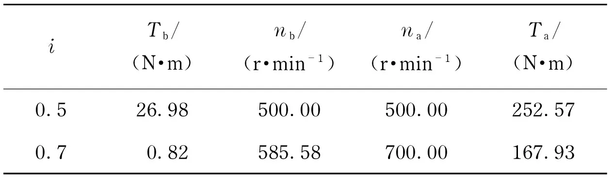
Relative displacement and velocity of wedging process of Fig.3a and Fig.3b were shown respectively in Fig.6a-6b and Fig.6c-6d. For both models, the processes were divided into three stages, namely slipping, wedging and binding stages respectively.
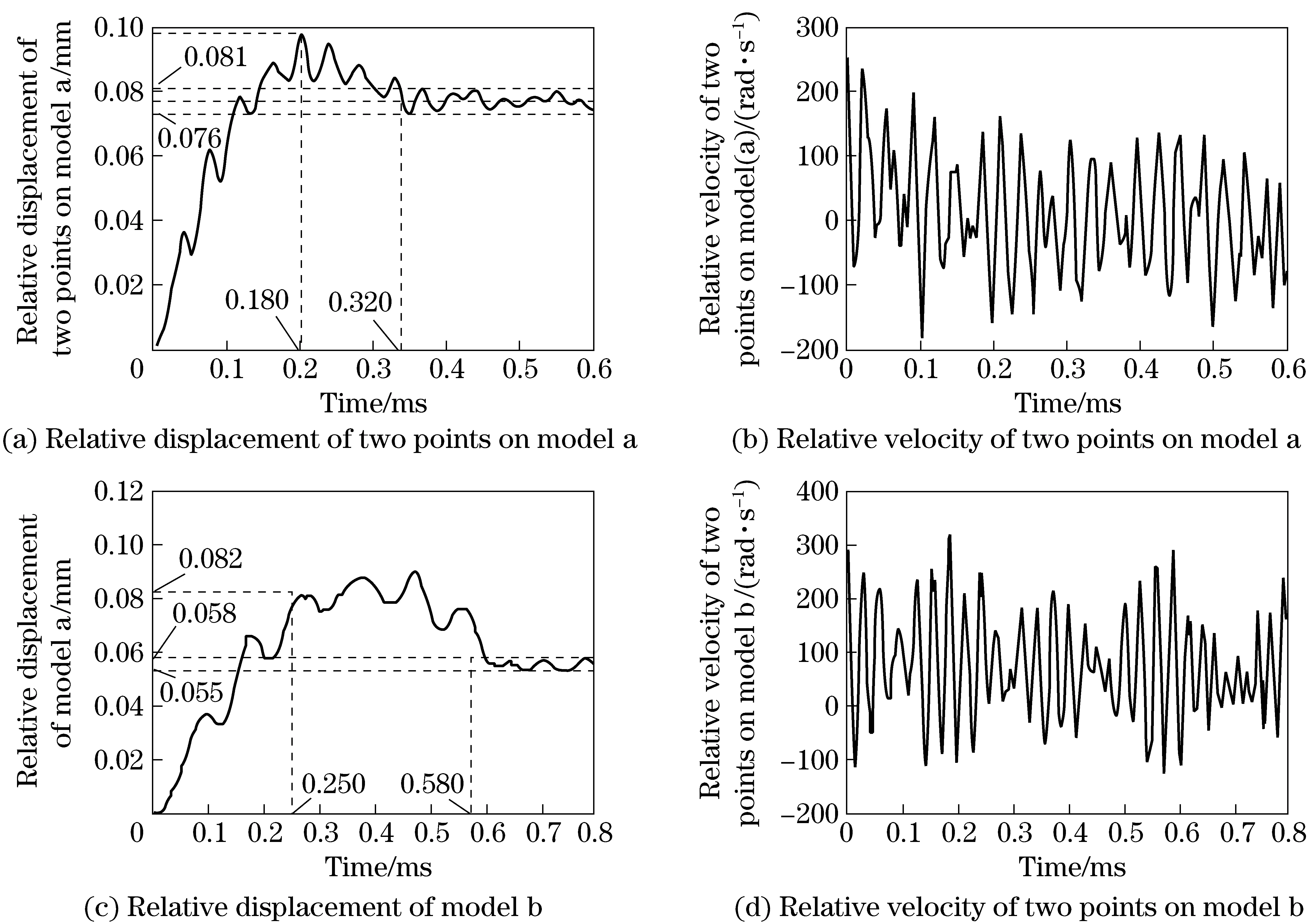
Fig.6 Relative displacement and velocity of two model measured by node A and B
① Slipping stage: from the beginning tot1=0.18 ms for the model in Fig.3a and tot1=0.25 ms for the model in Fig.3b, the relative displacement between two nodes was increasing and peak value of 0.10 mm emerged att1=0.18 ms. The relative velocity decreases while velocity of the inner ring is always higher than that of the outer ring. However, velocities of two nodes approached gradually.
② Wedging stage: fromt1=0.18 ms tot2=0.32 ms for model Fig.3a, and fromt1=0.25 ms tot2=0.58 ms for model Fig.3b, the velocity of the inner ring fluctuated near zero. The relative displacement fluctuated near 0.10 mm. It revealed when velocities of the two rings come to the same, the wedging stage began. Since amplitudes of relative velocity and displacement were relatively large, the overrunning clutch did not come to steady state.
③ Binding stage: fromt1=0.32 ms tot2=0.6 ms for model Fig.3a, and fromt1=0.58 ms tot2=0.8 ms for model Fig.3b, relative displacement fluctuated near constant values and little deviation (less than 2.5% of mean value) was found during this stage, then the inner ring and outer ring decelerated together until their rotating speed decreased to 500 r/min.
In the wedging process, the strength of the roller, inner ring and outer ring was calculated for these two kinds of contact surfaces separately.
Because rollers were vulnerable parts and easy to fail relatively in engineering applications, typical elements of contact regions of the roller to the inner ring and to the outer ring were chosen to show their wedging stress distribution illustrated in Fig.7 and Fig.8.

Fig.7 Stress-time curve of element A and B near contact region of roller and inner and outer rings of straight line model
Fig.8 Stress-time curve of element A and B near contact region of roller and inner and outer rings of logarithmic spiral model
For the model in Fig.3a from the beginning of wedging processt1=0.18 ms tot2=0.25 ms, the stress of contact region of inner ring element A was higher than strength limit of material [σs]=0.518 GPa. However at the meantime, stress of element B near the contact point was lower than strength limit.
Similarly for the model in Fig.3b from the beginning of wedging processt1=0.25 ms tot2=0.58 ms, the stress of contact region of inner ring element A was higher than strength limit of material [σs]=0.518 GPa. The stress of element B near the contact point was lower than strength limit. Empirical formula shows that[6]
(6)
Forthiskindofstructure,thestresslimitwasequalto0.258GPa,muchlowerthanvaluesgivenbyexplicitdynamicanalysis.Sothiskindoftraditionalmethodcannotpredictstrengthofanoverrunningclutchpreciselycomparedwithanexplicitdynamicanalysis.EngineeringapplicationalsoshowedthatyieldfailureoftherollermodelinFig.3ahappenedafteraboutonethousandtimesofwedgingduringoperatinglife,asshowninFig.9.
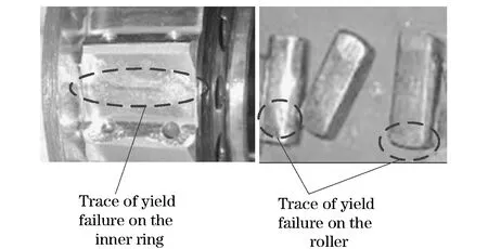
Fig.9 Failure graph of roller in an overrunning clutch
4 Conclusion
①Fromrelativedisplacementcurveandstress-timecurveofbothstructureofoverrunningclutch,itcanbeconcludedthattheringsgothroughthreestages,i.e.,slipping,wedgingandbinding.Andthemaximumpeakstressappearsinthewedgingstageforbothtwokindsofclutch.
②Anoverrunningclutchwithalogarithmicspiralcontactsurfacecanreducethepeakstressontherollerssignificantlycomparedwithaclutchwithstraightlinecontactsurface,butitneedsmorewedgingtime.
③Nearthecontactregionoftherollertotheinnerringandtotheouterring,contactstressoftherollertotheinnerringismuchlargerthanthatoftherollertotheouterringforbothclutches.Somaterialoftherollerandtheinnerringnearthecontactregioniseasytofailandthecontactpairneedstobeoptimizedinfurtherresearch.
[1] Wei Wei, Sun Tiantian, Yan Qingdong, et al. Study on explicit dynamics numerical simulation comparison of self-locking mechanism of achimedean and straight line types mould surface of one-way clutch[J]. Lubrication Engineering,2009,34(3):41-43,51.(in Chinese)
[2] Wei Wei, Liu Shucheng, Yan Qingdong, et al. Study on comparison analysis of planar and 3d numerical methods during wedging process of one-way clutch[J]. Acta Armamentarii, 2011(11):1305-1309. (in Chinese)
[3] Zhu Jingchang. Design and calculation of hydraulic torque converter[M]. Beijing: National Defense Industry Press, 1991:212. (in Chinese)
[4] Chen Dianhua, Shang Guizhi, Li Yuguang. Performance analysis of surpassing clutch with roll bodies type based on finite element method[J]. Journal of Engineering Design,2007,14(6):464-467. ( in Chinese)
[5] Cai Wei, Chu Yaxu, Ma Wenxing. Characteristic analysis of the idling condition of a dual-turbine torque converter[J]. Journal of Harbin Engineering University, 2011(7):948-952. ( in Chinese)
[6] Luo Yixin, Wu Bo. Study on finite element method for calculation of stress on external ring of one-way clutch [J].Engineering Science,2004, 6(9):56-59.(in Chinese)
[7] Zhang Lele, Tan Nanlin, Fan Li. The dynamics simulation and failure analysis of rolling bearings [J]. Journal of Shanghai Jiaotong University ,2007, 41(9):1506-1509.(in Chinese)
(Edited by Cai Jianying)
10.15918/j.jbit1004- 0579.201524.0211
TH 134; TH 114 Document code: A Article ID: 1004- 0579(2015)02- 0207- 06
Received 2013- 11- 25
Supported by the National Natural Science Foundation of China (51475041); the Ministerial Level Advanced Research Foundation (40402060103); the Ministerial Basic Products Innovation Program (VTDP2104)
E-mail: weiweibit@bit.edu.cn
猜你喜欢
东坡赤壁诗词(2022年1期)2022-02-25
阅读(中年级)(2021年9期)2021-10-21
课程教育研究(2021年22期)2021-04-13
四川党的建设(2018年20期)2018-11-02
中学生(2015年15期)2015-03-01
Defence Technology(2011年3期)2011-07-25
文史月刊(2009年12期)2009-12-31
 Journal of Beijing Institute of Technology2015年2期
- Journal of Beijing Institute of Technology的其它文章
- Nonlinear symbolic LFT model for UAV
- Novel scheme of high precision inertial measurement for high-speed rotating carriers
- Study on influencing factors of adapters separating with the underwater missile
- Fast-solving method for air-to-surface guided bombs’ allowable attack area
- Design and analysis of mechanical self-destruction and self-neutralization mechanism for submunition fuze
- Resilience approach for heterogeneous distributed networked unmanned weapon systems