The coupling characteristics of supersonic dual inlets for missile①
2015-04-24 07:32SUNZhenhuaWUCuisheng
固体火箭技术 2015年6期
SUN Zhen-hua,WU Cui-sheng
(China Airborne Missile Academy,Luoyang 471009,China)
The coupling characteristics of supersonic dual inlets for missile①
SUN Zhen-hua,WU Cui-sheng
(China Airborne Missile Academy,Luoyang 471009,China)
The numerical investigation and wind tunnel tests on the coupling characteristics of the dual inlets for the ducted rocket were presented. Once the dual inlets stop working, the windward inlet has to start first when the back pressure decreases to 16.9 times the static pressure of the inflow under stable state. By contrast, the leeward inlet can restart only if the back pressure decreases to 8.9 times the static pressure of the inflow. The results show that the inlets achieve the best performance when the leeward side reaches its critical state with certain angle of sideslip.
ducted rocket;dual inlets;coupling characteristics;numerical simulation;wind tunnel test
0 Introduction
The operation of the inlet determines the performance of the ducted rocket. The layout forms of the inlet can be various on the missile. “Meteor” and “HSAD” employ two inlets located at the downside of the missile; bilateral inlets are used on “ASMP” and “T3”. Four bilateral inlets are placed on “P77M” and “GQM-163A”.
Under the circumstances of critical phase of the ducted rocket, high maneuvering of the missile and intense perturbation of the airflow, the performance of the supersonic inlet could have certain mutation, including transient choked flow, inlet backflow and inlet buzz. For the unstable working characteristics of the inlet, large quantities of researches are performed, including mechanisms of inlet buzz[1-3], subcritical characteristics of the inlet[4-5], oscillation during starting of the inlet[6-8]and restart mechanism of the inlet[9-10].Researches mentioned above mainly focus on the working characteristics of the single inlet, for the system with multiple inlets, the working characteristics for the whole system is different from each single inlet when the incoming flow from multiple inlets mixes in the chamber abnormally. It is mainly attributed to the variation of the stable working boundaries, matching characteristics with the motor, start and restart characteristics, etc. Thus it is necessary to investigate the coupling characteristics of multiple inlets system.The study focus on the bilateral inlets system model of the missile and the whole process from regular work to working unstable and finally back to normal, in order to provide the solutions for the stable control of the inlet.
1 Numerical simulation
1.1 Inlet modeling
From Fig.1, the inlet employs bilateral mixed-compression model. The front dual cone is applied to compress the air. The inlet is relative longer because the air flows into the engine from the head. The air expands at radial and circumferential direction inside the inlet and finally flows into the combustor.
1.2 Flow solver
Fluent is used for the numerical simulation and Gauss-Seidel method is used for the time integration. Roe format with second order difference division is applied for the in-viscid convection flux. Realizablek-εmodel is applied for the turbulence model. Similarly, second-order upwind format is used and non-equilibrium surface function is applied for the region close to the wall. The convergence rule is based on the decrease of each residual of all the functions at three levels of magnitude. In addition, the back pressure of the inlet should be stable and the outlet flow should be constant for convergence requirement.
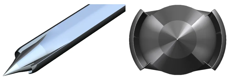
Fig.1 Schematic graph for the bilateral inlet
1.3 Boundary conditions
Fig.2 indicates boundary conditions used in the simulation. They are: pressure far-field, pressure outlet, no slip adiabatic wall. The typical state for the simulation is chosen asMa=3.0,H=10 km,attack angleα=0° ,yaw angleβ=5°.
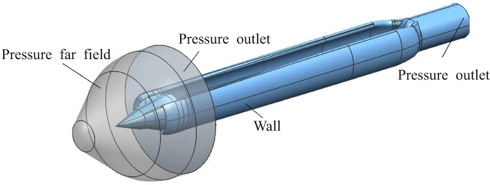
Fig.2 Schematic diagram of boundary conditions for inlet
1.4 Numerical grid
ICEM is applied for the generation of numerical grid for the inlet inside and outside flow region. In order to improve the precision and efficiency of the calculation, structured grid is applied and finer mesh is used locally to improve the precision. The thickness of the first mesh layer on the wall is set between 0.01mm to 0.1mm. The increasing ratio from the wall is set between 1.1 to 1.2. The element number is around 2 200 000 and is shown in Fig.3.

Fig.3 Schematic diagram of numerical grid for the head of the inlet
2 Results and discussion
Fig.4 shows the stable working state of the inlet in different throttle condition using steady calculation, as well as the throttle characteristics. More specifically, Fig.4(a) shows the overall throttle characteristics while Fig.4(b) indicates the throttle characteristics for each inlet. In this study, the variation of back pressure at combustor is modeled through increasing the exports of jet flow outside the combustor. From Fig.4, the flow coefficient of inlet is around 0.91 under supercritical condition. Meanwhile, the simulation results indicate that the flow coefficient of the inlet on the upwind side is 1.09 times that of the leeward side. The total pressure recovery coefficient, increasing with the increase of the percentage of blockage, achieve its maximum at 0.56 when the inlet is on the leeward side under supercritical condition. With the decrease of the flow coefficient, the total pressure recovery coefficient decreases correspondingly. The main reason is that the shock wave at the end of the inlet on the leeward side is pushed outside the lip, which results in the sudden drop of the performance. Moreover, with the percentage of blockage keeps increasing, the flow coefficient decreases continuously while the total pressure recovery coefficient increases a little bit (point 3 to point 4 in Fig.4(a)). When the flow coefficient is smaller than 0.82, the performance of the inlet will decrease drastically and the inlet cannot work stably. The Mach number distributions of the mid-surface of dual inlets under throttle condition are shown in Fig.5 and Fig.6.
(a) The overall throttle characteristics
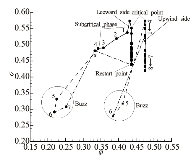
(b) The throttle characteristics for each inlet
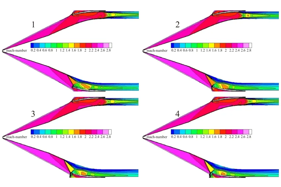
Fig.5 Mach number distribution of the mid-surface for the dual side inlet under throttle state
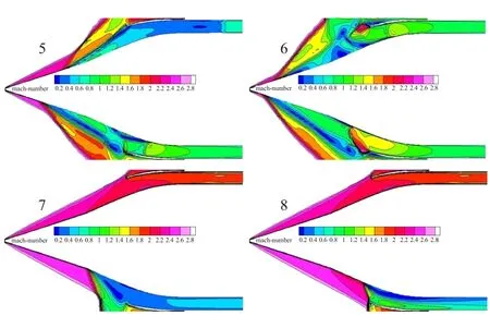
Fig.6 Mach number distribution of the mid-surface for the dual side inlet during restart process
If dual supersonic inlets are under the condition of sideslip, the inlet on the upwind side owns better performance of back pressure. Under the same back pressure of combustor, the position of the shock wave is more close to the front inside the inlet. Thus, with the increase of the back pressure to 17.7 times the static pressure of the incoming flow, the inlet on the leeward side will transform to the sub-critical state first(1#). At this time, the shock wave stays at the lip for the inlet on the leeward side while it will be located at the throat for the inlet on the upwind side. With the increase the back pressure, the overflows on the leeward side of the inlet increases while the inlet on the upwind side still stays at the critical state. Once the back pressure reaches 18.4 times the inflow pressure, the shock wave will be pushed outside the lip and then the inlets on both side will be in deep sub-critical state(5#、6#). In this case, the shock wave before the inlet is not stable, and the captured flow and the total pressure will be oscillating with the time.
If the pressure in the combustor is decreased to 16.9 times the static pressure of the incoming flow under the condition that dual inlets do not start, the inlet on the upwind side will restart first while the shock wave of the inlet on the leeward side still stay at the lip. The main reason for the difference of the back pressure between the non-start and restart of upwind inlet is that the mix-pressure design for the inlet has delay in the certain range (decrease around 1.5 times static pressure of the incoming flow). If the back pressure decreases continuously, the shock wave moves more closely to the lip but inlet still doesn't restart. Meanwhile, the inlet on the upwind side has already reached the super-critical state. If the back pressure decreases to 8.9 times the back pressure of incoming flows, the inlet on the leeward side restarts again. It is obvious that during the starting process, especially with the existence of the sideslip, dual inlets design is different from single inlet design in the engineering perspective, which is needed to pay more attention during the design.
3 Experimental setup
3.1 Test model and wind tunnel facility
During the experiment, the throttle is set at the mixing section of the blowing model. The back pressure of the chamber is modeled through adjusting the position of the throttle vertebral, thereby to obtain the characteristic curve for the inlet. In total 42 pressure holes are distributed along the outer cover and expansion section of the inlet blowing model to monitor the axial distribution of the wave system. For the measurement of total pressure, 81 pressure holes are set at the left and the right side of the export surface as well as the mixing section to measure the inlet characteristics. The inlet model is shown in Fig.7.
The blowing test of the inlet was performed using wind tunnel named as“FD-06”, half backflow short duration for subsonic, transonic and supersonic wind tunnel. The range of the Mach number is from 0.4 to 4.5. The cross-section area for the experimental section is 0.6 m×0.6 m and the length is 1.575 m. During the supersonic experiment, different Mach number can be obtained via using different nozzles. Two windows, with the diameter of 230 mm, for observation and flow display are equipped at each side of the inlet. Scimitar support machine is used to fix the test model. Shim is used to adjust sideslip angle. To adjust angle of attack, a normal mechanism is used for the angle in the range of -15°~15°,-10°~20° and 0°~30° while the special one is used for the range of -2°~38°.
The wind tunnel uses 8400 electronic scanning valve to measure the pressure. It could measure 128 pressure holes of the test model in the same time. The maximum speed of the valve is 50 kHz and the range is ±0.2 MPa. For the precision, the valve could reach ±0.05%F.S while ±0.01%F.S for the pressure calibration accuracy. Wind tunnel model setup is shown in Fig.8.
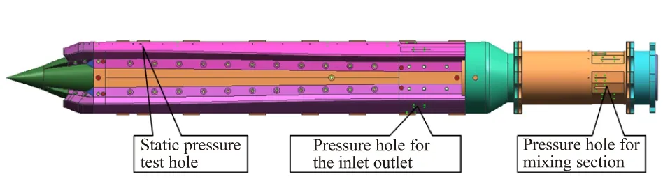
Fig.7 Schematic graph for inlet model
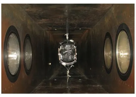
Fig.8 Wind tunnel model setup
3.2 Results for the blowing test
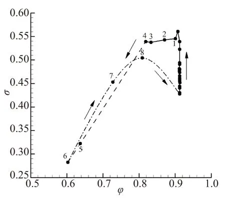
In the wind tunnel experiment for the inlet, the back pressure is adjusted by adding throttle vertebras at the outlet of the combustor. Fig.9 indicates the throttle curve for the blowing test of the inlet under the state ofMa=3.0,α=0°,β=5°. In Fig.8, the capturing flow coefficient is 0.93 when the dual inlets are in the state of super-critical. With the increase of the percentage of blockage, the capturing flow coefficient stays constant while the total pressure recovery coefficient increases. The performance of the dual inlets can reach their maximum when the total pressure recovery coefficient increases to 0.52. If the percentage of blockage increases continually, the inlet flow will decrease as well as total pressure recovery coefficient. However, the total pressure recovery coefficient cannot decrease more when the inlet flow keeps decreasing in the small scale. Interestingly, the performance of the inlet will decrease dramatically if the shock waves on both inlets are pushed outside the lips. In the same time, the pressure oscillates drastically as indicated in Fig.10, corresponding to the point 1, 2 and 3 in Fig.9. When the dual inlets stop operation, it is required to decrease the back pressure via decreasing the percentage of blockage, thereby to lead the inlet to restart.
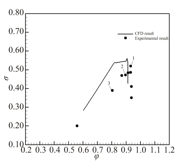
Fig.9 Inlet characteristic diagrams for wind tunnel experiment
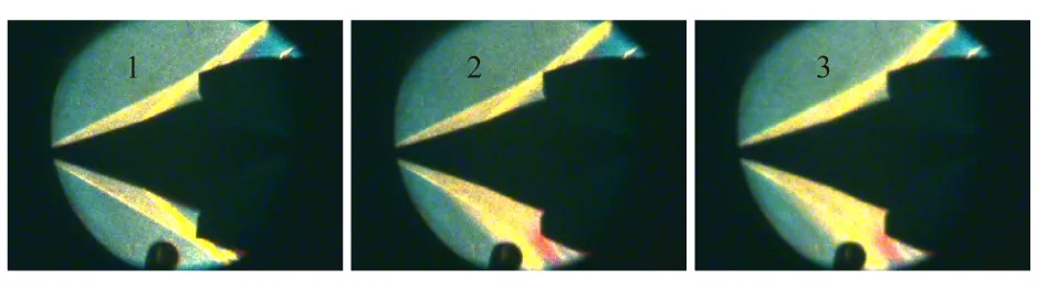
Fig.10 Sequence of schlieren images of the inlet under the condition of Ma=3.0,α=0°,β=5°
4 Conclusion
(1) With the sideslip angle of 5°, inlet on the leeward side reaches its critical point and the performance achieves its maximum(σ=0.56). After that, with the increase of back pressure, the flow of inlet decrease in the small amount in the beginning while it decreases drastically after a while. By contrast, the total pressure recovery coefficient almost remains constant in the beginning while it decreases drastically after.
(2) After dual inlets stops working, the inlet on the upwind side start first with the decrease of the back pressure and it remains consistently 16.9 times the inflow static pressure. In contrast, the inlet on the leeward side requires even more decreasing of the back pressure, around 8.9 times the inflow static pressure, to restart.
(3) With the existence of the attitude angle, the inlet in the system with multiple inlets does not have the same working state, which should be considered in the research.
[1] Lu P J,Jain L T. Numerical investigation of inlet buzz flow [J]. Journal of Propulsion and Power,1998,14(1):90-100.
[2] Yufeng Wang, Bao'e Yang. Study of the buzz mechanism of supersonic inlets[J]. Journal of Rocket Propulsion, 2008,34(1):17-22.
[3] Wooram Hong,Chongam Kim. Numberical study on supersonic inlet buzz under various throttling conditions and fluid-structure interaction[R]. AIAA 2011-3967.
[4] Newsome R W. Numberical simulation of near-critical and unsteady, subcritical inlet flow[J]. AIAA Journal, 1984, 22(10):1375-1379.
[5] Ferri A, Nucci L M. The origin of aerodynamic instablility of supersonic inlets at subcritical conditions[R]. NASA RM L50K30, 1951.
[6] Liu Zhansheng, Zhang Yunfeng, Tian Xin. Research on self-excited oscillation flows in inlet of ramjet[J].Journal of Aerospace Power,2008(9).
[7] Fujiwara H,Murakami A,Watanabe Y. Numerical analysis on shock oscillation of two-dimensional external compression intakes [R]. AIAA 2002-2740.
[8] Nishizawa U,Kameda M. Computational simulation of shock oscillation around a supersonic air-intake [R]. AIAA 2006-3042.
[9] Van Wie D M,Kwok F T. Starting characteristics of supersonic inlets[R]. AIAA 96-2914.
[10] Ryan Throckmorton and Joseph A Schetz. Experimental and computational investigation of a dynamic starting method for supersonic/hypersonic inlets[R]. AIAA 2010-589.
(编辑:薛永利)
弹用双进气道耦合特性
孙振华,吴催生
(中国空空导弹研究院,洛阳 471009)
针对某弹用双进气道系统之间的耦合特性进行数值模拟和风洞试验研究。结果表明,双侧进气道均不起动后,减小反压至16.9倍来流静压时,迎风侧进气道先起动,而背风侧进气道需要大幅降低反压至8.9倍来流静压才能实现再起动;有弹体侧滑角状态下,双进气道的背风侧进气道处于临界时,性能达到最大。
冲压发动机;双进气道;耦合特性;数值模拟;风洞试验
V435 Do cument code:A Article ID:1006-2793(2015)06-0793-05
10.7673/j.issn.1006-2793.2015.06.008
① Received date: 2015-03-03; Revised date: 2015-04-21。
Biography: SUN Zhen-hua( 1976—) ,male,doctor,speciality: ducted rocket design and research.
猜你喜欢
北京航空航天大学学报(2022年6期)2022-07-02
科技创新与品牌(2022年4期)2022-05-08
科技创新与品牌(2021年10期)2021-10-13
科技创新与品牌(2021年3期)2021-04-23
辣椒杂志(2021年4期)2021-04-14
北京航空航天大学学报(2020年3期)2021-01-14
固体火箭技术(2017年6期)2018-01-11
北京航空航天大学学报(2017年1期)2017-11-24
北京航空航天大学学报(2017年11期)2017-04-23
北京航空航天大学学报(2016年9期)2016-11-16