
Performance analysis of an O2/CO2 power plantbased on chemical looping air separation
2015-05-08 02:32GuPengfeiXiangWenguo
Gu Pengfei Xiang Wenguo
(Key Laboratory of Clean Coal Power Generation and Combustion Technology of Ministry of Education,Southeast University, Nanjing 210096, China)
Performance analysis of an O2/CO2power plantbased on chemical looping air separation
Gu Pengfei Xiang Wenguo
(Key Laboratory of Clean Coal Power Generation and Combustion Technology of Ministry of Education,Southeast University, Nanjing 210096, China)
The process of an O2/CO2power plant based on chemical looping air separation (CLAS) is modeled using the Aspen Plus software. The operating parameters and power consumption of the CLAS unit are analyzed. The CLAS system, thermal power generation system and flue gas cooling and compression unit (CCU) are coupled and optimized, and the temperature and flow of the flue gas extraction are determined. The results indicate that the net plant efficiency of CLAS O2/CO2power plant is 39.2%, which is only 3.54% lower than that of the conventional power plants without carbon capture. However, the O2/CO2power plant based on cryogenic air separation technology brings 8% to 10% decrease in the net plant efficiency. By optimizations, the net plant efficiency increases by 1.65%. The energy consumption of the CCU accounts for 59.7% and the pump accounts for 27.1%. The oxygen concentration from the chemical looping air separation unit is 12.2%.
chemical looping air separation; O2/CO2combustion; performance analysis
Coal, as a kind of primary energy, has the largest reserves and the most widely distribution in the world, and it is also the cheapest source of energy. About 45% to 50% of electricity around world is provided by coal-fired power plants. With the advantages of small investment and a short construction period, coal-fired power plants will still play a major role for a long time in the future[1]. In recent years, CO2emissions have caused global warming and frequent extreme weather, which has attracted much attention. Coal-fired power plants contribute much more CO2emissions, and the reduction in CO2emissions of power plants is necessary. However, the CO2emissions in power plants are characterized by low CO2partial pressure and high quantity of flue gas. By conventional air combustion, the main component in the flue gas is N2, while the concentration of CO2is only 10% to 15%,which means that the cost of CO2separation is extremely expensive and causes the net plant efficiency decline[2].
To increase the concentration of CO2in flue gas and decrease the cost of CO2separation, the oxy-fuel coal-fired technology (also called O2/CO2recycle combustion technology) was proposed, which uses O2/CO2mixed gas instead of air as the oxidant of fuel combustion to increase the CO2concentration in the flue gas. In the dry flue gas, the CO2concentration can be as high as 95% or more, which means that a high concentration of carbon dioxide can be gained easily after flue gas condensation and dehydration. It is a CO2capture technology of great potential. Nevertheless, the technology causes the net plant efficiency to decline deeply. The net plant efficiency decreases by 8% to 10% than that of the conventional pulverized coal power plant due to the large amount of oxygen for the combustion and much high power consumption of existing cryogenic air separation unit (ASU)[3].
Chemical looping air separation (CLAS) is a new oxygen generation technology, which is characterized by low investment and low power consumption. Applying this technology to generate oxygen instead of conventional ASU can promote the net plant efficiency of the oxy-fuel power plant. This work proposes a 1 000 MW ultra-supercritical coal-fired plant based on CLAS. Using Aspen Plus software, the process of the 1 000 MW CLAS O2/CO2power plant is modeled.
1 Chemical Looping Air Separation
Conventional oxy-fuel plant combusts oxygen produced by the cryogenic ASU. The ASU is the only large-scale oxygen generation method under operation commercially. This technology has a long history and is rather mature, and the oxygen content of the product reaches above 99%. However, the technology is energy-intensive, which decreases the net plant efficiency of an oxy-fuel power plant by about 10%.
Chemical looping combustion (CLC) was first proposed by Richter et al[4]. CLC is composed of two independent reactors: an air reactor and a fuel reactor. A suitable kind of metal oxide is selected as an oxygen carrier which cycles between the two reactors. Chemical looping with oxygen uncoupling (CLOU) based on CLC was proposed by Shulman et al[5]. Gaseous oxygen is released in the fuel reactor rather than lattice oxygen, which is mainly separated from CLC and avoids solid-solid reactions. CLAS technology was proposed based on CLOU. Moghtaderi[6]studied the performance of CLAS under a vapor atmosphere and the results show that a mixed oxygen carrier made from Mn3O4/Mn2O3and CoO/Co3O4at a mass ratio of 1∶1 achieves a better performance. The preliminary cost analysis shows that the specific power consumption of the CLAS process is about 0.045 (kW·h)/m3of air produced, which is approximately 11% of the specific power consumption of conventional cryogenic air separation systems. Mei et al.[7]studied the thermodynamics and reaction mechanism of the deoxygenation reaction of Cu/Co/Mn based oxygen carriers. They found that the deoxygenation reactivity of the Mn-based oxygen carrier is higher when the Cu-based oxygen carrier is lower and the Co-based oxygen carrier is moderate. Zhao et al.[8]modeled CLAS systems using Mn-oxide and Co-oxide as oxygen carriers, and CO2as the medium gas, and analyzed their performances. The results show that when the oxidation temperature is 890 ℃ and the reduction temperature is 880 ℃, the performance of the Mn-based oxygen carrier is better with specific power consumption of 0.151 (kW·h)/kg and 13.2% oxygen concentration. Mn3O4/Mn2O3is used as the oxygen carrier of the CLAS system in this work.
The CLAS concept using CO2as the medium gas is shown in Fig.1. Due to the higher oxygen partial pressure in the oxidation reactor, Mn3O4is oxidized to Mn2O3at a high temperature. In the reduction reactor, Mn2O3is reduced back to Mn3O4and releases oxygen because of the lower partial oxygen pressure in CO2.
(1)
(2)
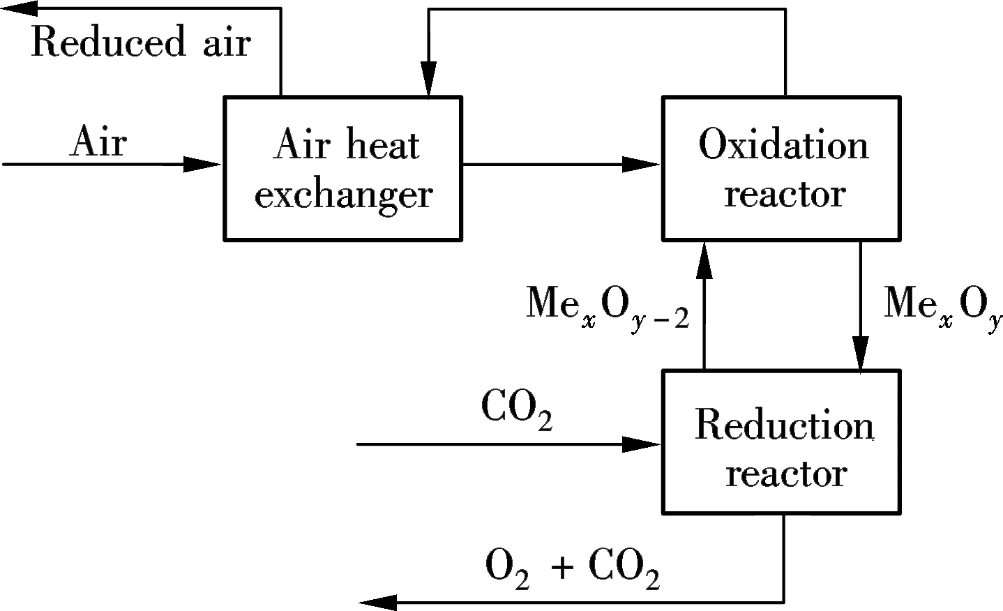
Fig.1 Chemical looping air separation concept
2 O2/CO2 Recycle Combustion Plant
As shown in Fig.2, an O2/CO2recycle combustion plant integrating CLAS is proposed and the system mainly consists of three sections: 1) CLAS unit; 2) Conventional power plant; and 3) Flue gas cooling and compression unit.

Fig.2 O2/CO2 recycle combustion plant based on CLAS
High temperature flue gas extracted from the boiler furnace exit flows into the reduction reactor after undergoing cyclone separation and the booster fan. The flue gas is rich in carbon dioxide and water vapor, and flows into the bottom of reduction reactor of the CLAS unit. The CLAS unit is composed of an oxidation reactor, a reduction reactor, and air heat exchangers. After being preheated in heat exchangers, fresh air is induced from the bottom to the oxidation reactor where the reduced oxygen carrier from the reduction reactor is regenerated. After solid oxygen carrier separation, the oxygen depleted air is discharged into the atmosphere after heat recovery in heat exchangers. The oxygen carrier goes into the reduction reactor and releases oxygen into high temperature flue gas. The oxygen concentration in the flue gas increases and is ready for the combustion of coal after the removal of the solid oxygen carrier. The reduced oxygen carrier recycles into the oxidation reactor through the loop seal. The air preheater is no longer needed, which differs from the conventional coal-fired boiler. Liquid carbon dioxide is obtained after multi-stage water vapor condensations and compressions of exhaust flue gas, and the non-condensate gases, mainly comprised of oxygen, can be used as combustion air.
3 O2/CO2 Combustion System Modeling and Analysis
3.1 CLAS unit
The CLAS unit is modeled using Aspen Plus software, as shown in Fig.3. Fresh air preheated in the heat exchanger (EX block) flows into the oxidation reactor (OXD block), and oxidizes Mn3O4. The solid product in the oxidation reactor is mainly Mn2O3and the fresh air is turned into oxygen depleted air. After undergoing the cyclone separator (OX-SP block), the oxygen depleted air flows into the heat exchanger (EX block) for heat recovery to heat the fresh air. Then, the separated solid Mn2O3enters the reduction reactor (RED block). It is reduced to Mn3O4, and it releases oxygen to the flue gas. The oxygen-containing flue gas is induced to the boiler and burns with coal. Solid Mn3O4recycles back to the oxidation reactor (OXD block) for regeneration.
The simplified air components are N2(78.12%), O2(20.95%) and Ar (0.93%) with the ambient pressure of 101.325 kPa and the temperature of 25℃. Reaction (1) is exothermic while reaction (2) is endothermic. Therefore, heat of reaction (2) is mainly supplied by the sensible heat of high temperature flue gas or the electric oven.
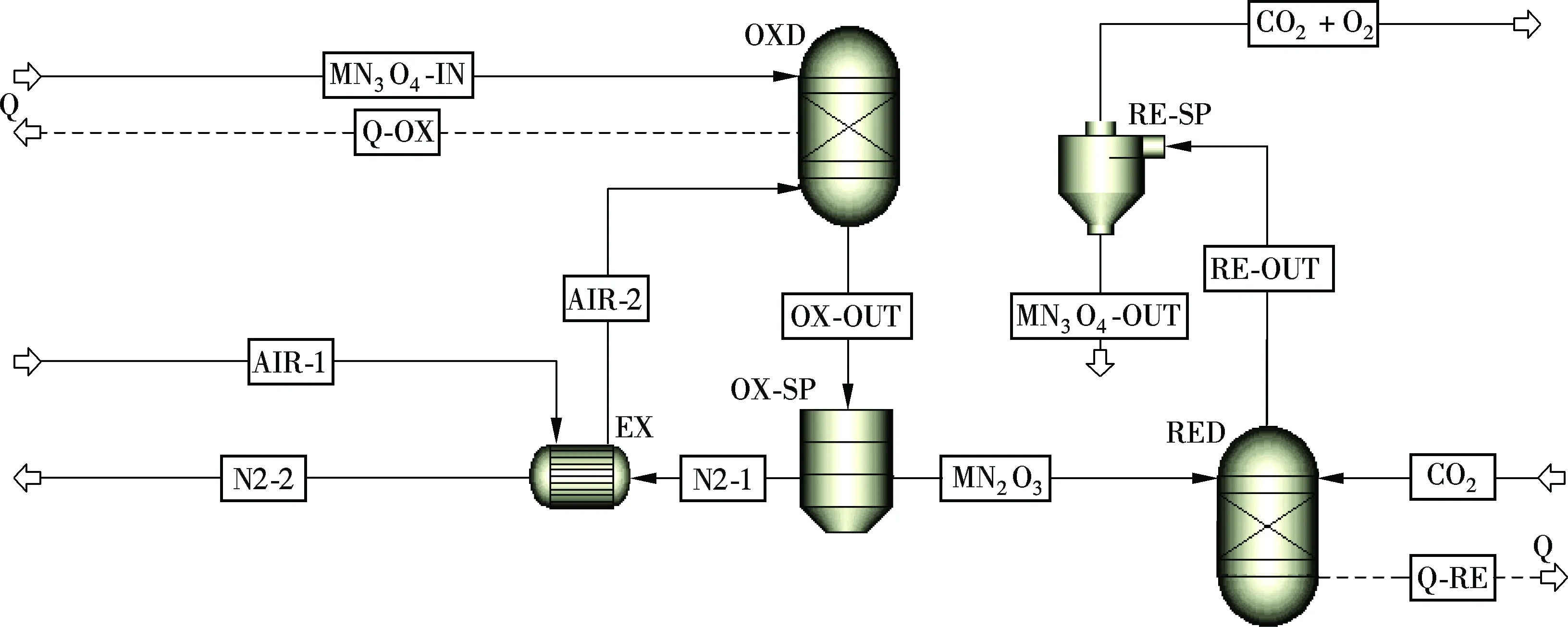
Fig.3 The model of CLAS unit
Tab.1 shows the results of the simulation of CLAS unit under different flue gas temperatures. Coal burnout is similar in air and under the oxy-fuel (O2/CO2) conditions with 11% to 14% O2[9]. Under higher flue gas temperatures as in Case 2, less flue gas is needed to produce 1 kg O2, which means that there is a high heat exchange surface between flue gas and water/steam in the boiler and a higher power generation. Moreover, less air means lower power consumption from the booster fan, lower oxygen depleted air heat losses, and a higher O2concentration in the oxygen-containing flue gas. Case 2 has an obvious advantage compared with Case 1.

Tab.1 Simulation under different flue gas temperatures
3.2 CLAS-based O2/CO2combustion power plant
The thermal power generation section of the O2/CO2combustion power plant is the same as that of the conventional power plant.
Assumptions on the simulations of boiler combustion are made as follows: 1) Coal combustion is divided into two processes: pyrolysis and coal char burning; 2) Burnout of coal is 99.5%; 3) Combustion is under barometric pressure. The proximate analysis and ultimate analysis of coal are shown in Tab.2, and the lower heating value (LHV) is 22.55 MW/kg[10]. Tab.3 and Tab.4 show the results of simulations.
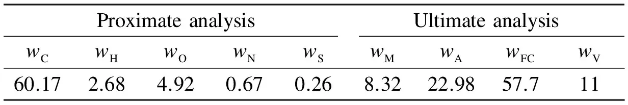
Tab.2 Proximate analysis and ultimate analysis of coal %
As shown in Tab.3, the simulation results of the conventional power plant are similar to those of the CLAS-based power plant, which indicates that the simulations are reasonable. To maintain the thermal equilibrium of the boiler, circulating flue gas is composed of two parts: one from the furnace exit (1 099 ℃) and the other from exhaust flue gas (378.1 ℃), which results in the decrease in circulating flue gas temperature. Therefore, the power consumption of CLAS increases.

Tab.3 Summary of simulation results
As seen from Tab.4, the CO2concentration of exhaust flue gas of the CLAS-based O2/CO2plant is apparently higher than that of the convention power plant, over 97% in dry flue gas, and the CO2-rich flue gas is ready for CO2capture.
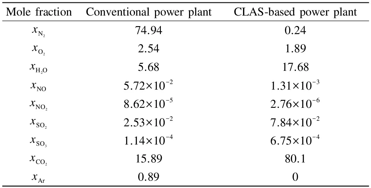
Tab.4 Mole fraction of gas components in furnace exit %
3.3 Cooling and compression unit (CCU)
Four stages in compression, cooling and water vapor separation are selected for CO2liquidation. Exhaust flue gas from the boiler exit is cooled to 25 ℃. After the removal of the condensate, it is compressed to a higher pressure, and then flows to the next stage for further cooling, water vapor condensation, and compression in four stages. The flue gas is compressed to 10 MPa in the fourth stage and cooled to 25 ℃, and CO2is liquefied as fluid. Centrifugal-flow compressors with 85% isentropic efficiency and 98% mechanical efficiency are chosen in the simulations with the compression ratio of 3.5, 3.5, 3.5 and 2.5 in four stages. The simulation results show that CO2in the flue gas is as high as 97.14%, as shown in Tab.5. The non-condensate components are N2, O2, water vapor, NOxand SOx. Also, the power consumption of the whole CCU process is 101.96 MW.

Tab.5 Simulation results of CCU
4 Performance Analysis and Optimization
4.1 Performance analysis of CLAS
Reaction (2) in the reduction reactor of the CLAS unit is endothermic. To keep the reactor temperature, a quantity of heat is needed and may come from: 1) The heat carried by solid materials from the oxidation reactor, 2) The heat brought by higher temperature flue gas; 3) The electric oven. The reduction temperature affects the performance of the CLAS unit. Tab.6 shows the results when the reduction temperature is increased by 5 ℃.

Tab.6 Effects of the reduction temperature on the performance of the CLAS unit
As seen from Tab.6, with the increase in the reduction temperature by 5 ℃, the O2/CO2gas temperature increases by 5 ℃ as well, and the O2concentration is increased by 0.8%. The flue gas temperature in the furnace exit is increased by 1.3 ℃. It has little effect on the thermal load of the boiler and the power output, but the power of the electric oven is increased by 88.72 kW, and more power is consumed and so the net plant efficiency decreases.
However, decreasing the reduction temperature means a decrease in the O2concentration in O2/CO2and the decrease in the burnout of coal. Hence, it is reasonable to maintain the reduction temperature at about 762 ℃ and an O2concentration of 12.2%.
4.2 Optimization of CCU
水,冒着热气,只有大半桶。田志芳立即抖散行李,取出搪瓷缸,舀半缸,猛喝一口,差点全喷出来。水,又苦又涩,田志芳看看铁桶,看看茶缸,眼泪一下涌出来,这一路她没哭,她提醒自己是班长,要带头做表率,不能哭,不能不坚强,可这水,这又苦又涩的水,像她眼泪一样的水,让她的眼泪汩汩地流出来。田志芳这会儿强烈思念家乡。
In the simulation, the boiler exhaust flue gas is about 378.1 ℃. Particulate removal, cooling, water vapor condensation and separation are needed before flue gas compression. To remove water vapor in the flue gas, an appropriate cooling temperature is needed. The volume fraction of CO2in flue gas is calculated according to the flue gas condensing temperature. The volume fraction of CO2increases when the temperature decreases, especially when the temperature is lower than 50 ℃. Circulating water (CW) is usually adopted as the cooling medium. Assuming that the flue gas is cooled to 25 ℃, about 140 MW heat may be recovered for further use.
After being cooled to 25 ℃, the flue gas is compressed for cooling and water vapor separation. Higher outlet pressure means higher power consumption. Water vapor volume fraction and power consumption are also simulated according to the outlet pressure. Water vapor volume fraction almost stays unchanged when the outlet pressure is higher than 3 MPa. In order to decrease the power consumption, the optimum option is to compress the flue gas to 3 MPa in the first three stages and then to 10 MPa in the 4th stage, and it has the minimum power consumption. The first three stages are of the same compression ratio of 3.1. The power of 23.56 MW can be saved.
In order to make full use of exhaust flue gas heat energy and improve the net plant efficiency, the heat from the flue gas is used to heat the low-pressure feed water in stage 5 and stage 6, and after each stage of compression, the compressed flue gas is used to heat the low-pressure feed water in stage 7 and stage 8 before the CW coolers, as shown in Tab.7. Steam extractions from steam turbine for the regenerative system decrease and turbine power increases by 17.5 MW.

Tab.7 Steam extraction flow for regeneration before and after optimization t/h
4.3 Power consumption analysis
We can see from Tab.5 that SO2in the flue gas is also liquefied when CO2is liquefied. The critical point of CO2is 7.4 MPa/31 ℃ and that of SO2is 7.9 MPa/157.8 ℃. Therefore, the desulfurization of flue gas is unnecessary. The power consumption of desulfurization in the conventional power plant accounts for 1% of total capacity, and about 10 MW is saved from the O2/CO2plant.
From Tab.8 we can see that, in the CLAS O2/CO2plant, the power consumption of CCU is the largest, accounting for 66.2% of the total, and that of the pump accounts for 22.6%. After optimization, the power consumption of CCU declines to 59.7% of the total while that of the pump is 27.1%. Due to the recycling of flue gas, the exhaust flue gas flow of the O2/CO2system is much less than that of the conventional power plant and the heat losses are much lower than those of the conventional plants. More steam and more power are produced as shown in Tab.3. The net plant efficiency of the optimized CLAS O2/CO2plant is 1.65% higher than that of the un-optimized, and only 1.89% lower than that of the conventional plant without CO2capture.

Tab.8 Power consumption comparison between the conventional plant and the O2/CO2 power plant
5 Conclusion
A 1 000 MW O2/CO2power plant based on chemical looping air separation is proposed. The system performances are simulated using the Aspen Plus software, and are compared with the conventional power plant. The aim is to determine the possibility of using the CLAS O2/CO2power plant. High temperature flue gas extracted from the furnace exit is used to absorb oxygen in the CLAS unit. The concentration of oxygen from the CLAS unit is 12.2% under a 787 ℃ oxidation temperature and 762.4 ℃ reduction temperature. The oxygen containing flue gas, together with the flue gas extracted from the exhaust, is used as the circulating gas. The net plant efficiency of the CLAS O2/CO2system is 39.2% when the CO2is compressed to 10 MPa, 3.54% lower than the conventional power plant without carbon dioxide capture. When the heat of the exhaust flue gas in CCU is used in the regenerative system, the net plant efficiency of the optimized CLAS O2/CO2plant is 40.85%, 1.89% higher. The CO2concentration of 97.14% is achieved after CCU.
Nonetheless, further work is needed to verify the possibility of CLAS, for example, to find a proper oxygen carrier to design the CLAS unit, etc. Due to the overwhelming performance in the carbon capture, the CLAS O2/CO2plant is worthwhile investigating in the later work.
[1]Wigley T M L, Richels R, Edmunds J A. Economic and environmental choices in the stabilization of atmospheric CO2concentration [J].Nature, 1996, 379(6562): 240-243.
[2]Li Z, Zhang T, Cai N. Experimental study of O2-CO2production for the oxyfuel combustion using a Co-based oxygen carrier [J].Industrial&EngineeringChemistryResearch, 2008, 47(19): 7147-7153.
[3]Yan W, Mi C. Economic analysis of a 300 MW utility boiler with oxygen-enriched combustion [J].JournalofChineseSocietyofPowerEngineering, 2010, 30(3): 184-191. (in Chinese)
[4]Richter H J, Knoche K F. Reversibility of combustion processes [C]//ACSSymposiumSeries. Oxford University Press, 1983, 235: 71-85.
[5]Shulman A, Cleverstam E, Mattisson T, et al. Manganese/iron,manganese/nickel,and manganese/silicon oxides used in chemical-looping with oxygen uncoupling (CLOU) for combustion of methane [J].Energy&Fuels, 2009, 23(10): 5269-5275.
[6]Moghtaderi B. Application of chemical looping concept for air separation at high temperatures [J].Energy&Fuels,2009, 24(1): 190-198.
[7]Mei D, Zhao H, Yang W, et al. Oxygen release kinetics and mechanism study on Cu-, Co-, Mn-based oxygen carrier[J].JournalofFuelChemistryandTechnology, 2013, 41(2): 235-242.
[8]Zhao Y, Xiang W, Chen S. Performance evaluation of chemical looping air separation/oxygen production at high temperatures [J].JournalofSoutheastUniversty:NaturalScienceEdition, 2013, 43(4): 809-813. (in Chinese)
[9]Rathnam R K, Elliott L K, Wall T F, et al. Differences in reactivity of pulverised coal in air (O2/N2) and oxy-fuel (O2/CO2) conditions [J].FuelProcessingTechnology, 2009, 90(6): 797-802.
[10]Kong H, Liu Z, Chen S, et al. Process simulation and optimization of a 600 MW O2/CO2power plant [J].ProceedingsoftheCSEE, 2012, 32(2): 53-60. (in Chinese)
[11]Xiang W, Chen S, Xue Z, et al. Investigation of coal gasification hydrogen and electricity co-production plant with three-reactors chemical looping process [J].InternationalJournalofHydrogenEnergy, 2010, 35(16): 8580-8591.
[12]Xiang W, Wang S, Di T. Investigation of gasification chemical looping combustion combined cycle performance [J].Energy&Fuels, 2008, 22(2): 961-966.
基于化学链制氧的O2/CO2燃烧电站性能分析
顾鹏飞 向文国
(东南大学洁净煤发电及燃烧技术教育部重点实验室, 南京 210096)
采用Aspen Plus软件对基于化学链高温空分制氧技术(CLAS)的O2/CO2燃烧电厂全过程进行建模,对化学链高温空分单元进行运行参数及功耗分析,并对化学链高温空分单元、锅炉热力发电系统和烟气冷却压缩单元(CCU)进行耦合并优化,确定高温烟气抽取温度及抽取流量.结果表明,O2/CO2燃烧系统的净效率为39.2%,仅比不能进行碳捕集的常规电厂低3.54%.然而,基于深冷空分技术的O2/CO2燃烧系统会使得全厂净效率下降8%~10%.当采取优化措施后,O2/CO2燃烧系统效率能够提高1.65%.烟气冷却压缩单元能耗占总能耗的59.7%,泵能耗占27.1%.化学链制氧单元的供氧浓度为12.2%.
化学链空分制氧;O2/CO2燃烧;性能分析
TK114
Foundation items:The National High Technology Research and Development Program of China (863 Program) (No.2012AA051801), the National Natural Science Foundation of China (No.51176033).
:Gu Pengfei, Xiang Wenguo. Performance analysis of an O2/CO2power plant based on chemical looping air separation[J].Journal of Southeast University (English Edition),2015,31(2):194-199.
10.3969/j.issn.1003-7985.2015.02.006
10.3969/j.issn.1003-7985.2015.02.006
Received 2015-01-08.
Biographies:Gu Pengfei (1990—), male, graduate; Xiang Wenguo (corresponding author), male, professor, wgxiang@seu.edu.cn.
猜你喜欢
化工管理(2022年13期)2022-12-02
昆钢科技(2022年2期)2022-07-08
当代水产(2021年10期)2022-01-12
建材发展导向(2021年23期)2021-03-08
测控技术(2018年2期)2018-12-09
华人时刊(2018年15期)2018-11-10
中国资源综合利用(2016年2期)2016-01-22
天津冶金(2014年4期)2014-02-28
河南科技(2014年14期)2014-02-27
河南科技(2014年12期)2014-02-27
 Journal of Southeast University(English Edition)2015年2期
- Journal of Southeast University(English Edition)的其它文章
- Adaptive modulation in MIMO optical wireless communication systems
- An improving energy efficiency cooperation algorithm based on Nash bargaining solution in selfish user cooperative networks
- Model of limestone calcination/sulfation under oxy-fuel fluidized bed combustion
- A novel carbon trap sampling systemfor coal-fired flue gas mercury measurement
- Applicability of Markov chain-based stochastic modelfor bubbling fluidized beds
- Composite bioabsorbable vascular stents via 3D bio-printingand electrospinning for treating stenotic vessels