
Polarization sensor and MEMS integrated navigation technology
2015-06-05 14:51LILeileiLIUKaiCHENJiabinLIUHuiyaYANGLiming
中国惯性技术学报 2015年2期
LI Lei-lei, LIU Kai, CHEN Jia-bin, LIU Hui-ya, YANG Li-ming
(School of Automation, Beijing Institute of Technology, Beijing 100081, China)
Polarization sensor and MEMS integrated navigation technology
LI Lei-lei, LIU Kai, CHEN Jia-bin, LIU Hui-ya, YANG Li-ming
(School of Automation, Beijing Institute of Technology, Beijing 100081, China)
MEMS have been the hotspot in inertial measurements applications recently due to their advantages of low-cost, high reliability, micro size, etc. But MEMS cannot be used in initial alignment alone because of its drift and noise. Since bionic polarization navigation sensor’s errors are not divergent, it can restrain the divergence if polarization navigation sensor and MEMS become an integrated navigation system. Experiments are made which show that the data of polarization navigation sensor are not divergent, and the yaw angles provided by polarization navigation sensor can be used to accomplish the initial alignment. In navigational state, an odometer can be used to provide horizontal velocity and form an integrated navigation system with MEMS and the polarization navigation sensor, in which the velocity drifts can be effectively suppressed through the compensation of Kalman filter. The experiments verify the effectiveness of the integrated navigation system
polarization navigation; MIMU; Kalman filter; initial alignment; odometer
Bionic polarization navigation is a new kind of navigation methods, which gets navigation information by measuring the polarized features[1-3]. In nature, sunlight will be polarized after scattering by the molecules in the atmosphere, forming a polarization pattern which is the symmetry of the line of zenith and sun[4-5]. Some animals like desert ants can detect the navigation information from their own polarization vision. The information can be obtained by simulating the polarization vision of animals through photoelectrical devices.
Micro Inertial Measurement Unit (MIMU) is made up of three gyroscopes and three accelerometers which are integrated in one silicon substrate. The gyroscopes and accelerometers are installed in pairs on three perpendicular surfaces[6]. The advantages of MIMU, which is mainly made up of micro-electromechanical systems (MEMS), are small in size, light in weight, low-cost, high reliability, suitable for batch production, etc. But owing to low accuracy and quickly diverged errors, the MIMU cannot accomplish the navigation alone. It is usually combined with other navigation devices in application[7-10].
Polarization navigation, which belongs to passive navigation, is well covered and without electromagnetic interferences. Whether sunny or cloudy, even during the sunrise, the sky polarized light can always be used to navigate, and also can navigate without latitude limitation.Since the polarization navigation sensor’s errors don’t diverge, we can integrate bionic polarization navigation sensor with MIMU, and complete initial alignment with MIMU aided by polarization navigation sensor. Thus the errors accumulation can be restrained effectively, and the integrated navigation system can be applied.
In the stage of initial alignment, the polarization navigation sensor is used to provide the yaw angle, and the MIMU is used to calculate the roll angle and the pitch angle. In the stage of navigation, the odometer is used to provide the northward velocity and eastward velocity, thus by Kalman Filter, we can complete the integrated navigation.
1 Principle of polarization navigation sensor and MEMS integrated navigation system
1.1 Calculation of yaw angle
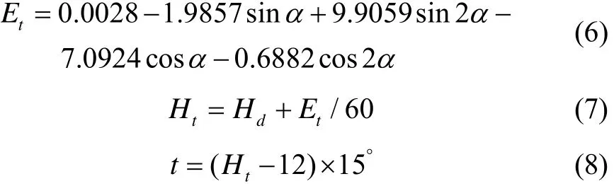
The angle of body long axis and the solar meridian φ can be measured by polarization sensor. In order to obtain the information of yaw angle[5], it is still essential to get solar elevation hsand solar azimuth As. According to the year Y that you carry out the experiments, the solar declination δ can be found as follows:

According to the time and the longitude of observation point, we can get solar hour angle t:

Where Hdis local time, Hand Mrepresent hours and minutes of observation point,λand Lrepresent longitude and minutes of longitude.
The solar elevationhsand azimuthAscan get as follows:
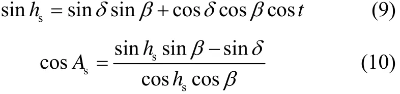
Through the polarization navigation sensor, we can get the angle φ between body long axis and the solar meridian and solar azimuth As. Through calculation, we can get the yaw angle as follows:

1.2 Initial alignment of integrated navigation system
The accuracy of gyroscopes and accelerometers in MIMU is low, so it cannot detect the rotation angular velocity of the earth and the acceleration of gravity to complete the initial alignment independently. So it is necessary to confirm initial azimuth with other information. And the polarization navigation sensor system can provide the yaw angle, so it can be an auxiliary sensor in the process of initial alignment of MIMU.
Let’s define that n is the geographic coordinate system, where Xn, Yn, and Znindicate east, north and up, and b is body axis coordinate system, where Xb,Yb,Zbindicate right, front and up. The initial alignment is to find attitude matrix, just by making sure the yaw angle ψ, the pitch angle θ and the roll angle λ. Supposing the projection of gravity is in body axis coordinate systemgb=()T, the projection of gravity is in local geographic coordinate system, gn=()T=(00-g)T, and the static base initial alignment gb=gn, we can get:
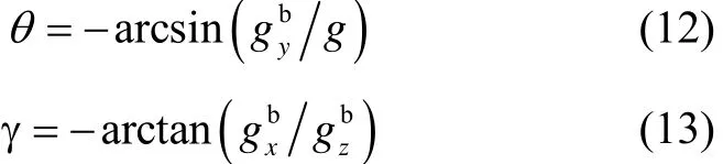
Considering the data from accelerometers in MIMU and the yaw angle from polarization sensor, the attitude matrix can be ontained. In real systems, the data from the accelerometers and polarization navigation sensor need to be processed with IIR low-pass filter.
1.3 Establish KF mathematic model
The Kalman filter state equation used in integrated navigation can be expressed as:

From Eq. (1), the state vector is:
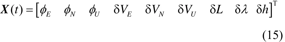
From Eq. (2), φE, φN, φUindicate the mathematic platform misalignment angles, δVE,δVN,δVUindicate the velocity errors of east, west and day directions, δLand δλindicate the errors in longitude, latitude and height[8].
The observation equation can be expressed as follows:

We choose the difference values of the heading angle of polarization navigation sensor and MEMS as observations:

Observation matrix of system:

Observation error matrix of white noise:
According to the state equation and observation equation of the integrated navigation system, we can use the Kalman Filter.
2 Simulation and result analysis
In order to verify the performance of the navigation system which is integrated by polarization navigation sensor and MEMS sensor, we carry out some simulation experiments. The polarization angle information used in this paper is collected by School of Optical Science in Beijing Institute of Technology. The MEMS IMU, whose product model is WGC-1A, is developed by Tsinghua University. Before the integrated navigation, we collect almost 25 min of MEMS sensor data and polarization navigation sensor data. Finally, we select last 5 min data for initial alignment.
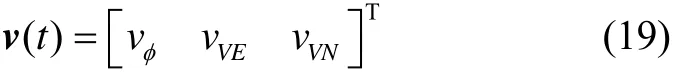
The data collected by MEMS are shown in Fig.1 to Fig.4.
Through the IIR low-pass filter, we can see that the data from the Fig.3 and Fig.4 are better than the data that not use the IIR low-pass filter. We can see that the root mean of square data that use IIR low-pass filter are less than those without using IIR low-pass filter. Tab.1 only intercept a part of accelerometer data as shown.
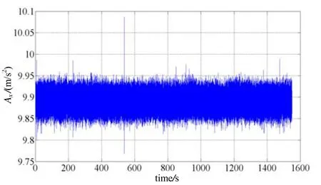
Fig.1 Data of X-axis gyroscope without IIR low-pass filter

Fig.2 Data of X-axis accelerometer without IIR low-pass filter
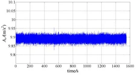
Fig.3 Data of X-axis accelerometer with IIR low-pass filter
Fig.4 Data of X-axis gyroscope with IIR low-pass filter

Tab.1 Test results of IIR low-pass filter
We use 5 min of data from IIR low-pass filter to do initial alignment. As we know, we use the pitch angles and the roll angles provided by MEMS sensor, and the yaw angles provided by polarization navigation sensor to accomplish the initial alignment.
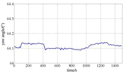
Fig.5 Yaw angle of polarization navigation sensor
And then, we get the initial attitude angles, which are θ=-1.1058°, γ=-0.4698°, and ψ=64.1144°. And the route of experiment is designed and marked in Fig.6, the route from north gate of Beijing Institute of Technology. The total mileage of this experiment is more than 4 km.
From the route, we can see that the car of experimentmake four turns, and the four turns are shown obviously in Fig.9. From Fig.10 and Fig.11, we can see that the divergence of eastward velocity and northward velocity is very large, the divergence of eastward velocity is more than 50 m/s, and the divergence of northward velocity is more than 60 m/s.
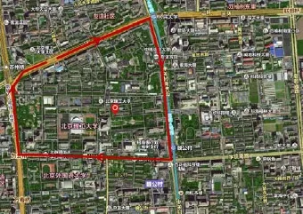
Fig.6 Route of experiment
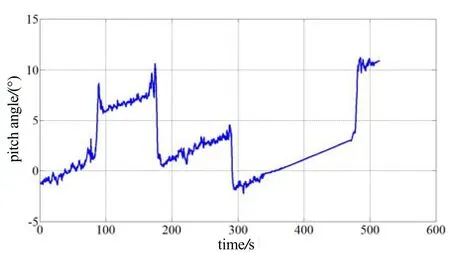
Fig.7 Pitch angle of integared navigation system without Kalman filter
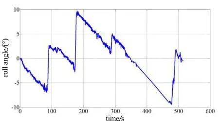
Fig.8 Roll angle of integated navigation system without Kalman filter
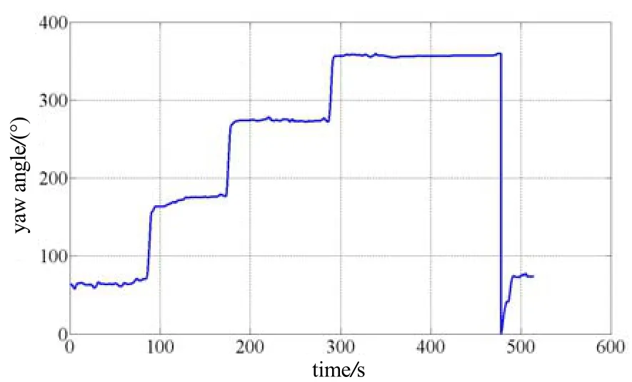
Fig.9 Yaw angle of integated navigation system withnot Kalman filter
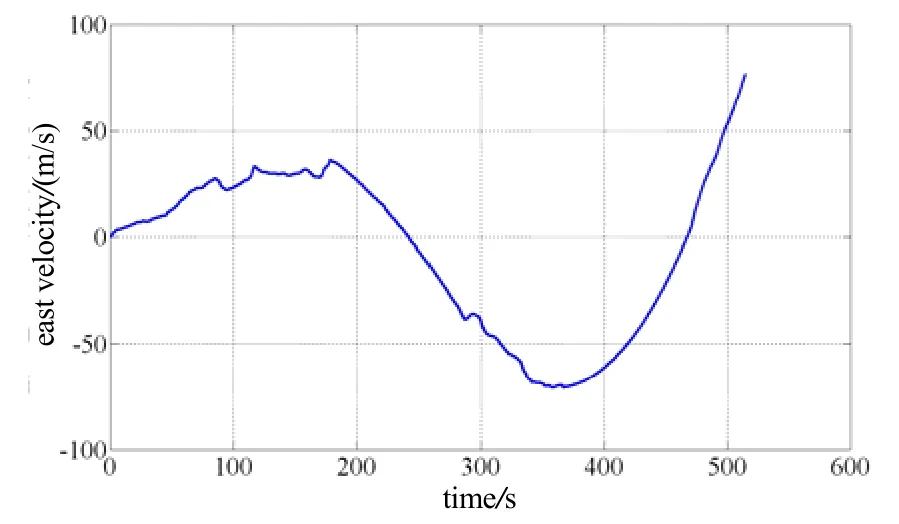
Fig.11 Eastward velocity of integated navigation system withnot Kalman filter
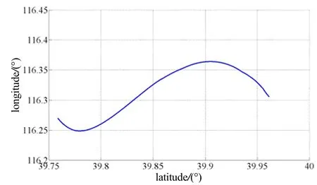
Fig.12 Position of integared navigation system withnot Kalman filter
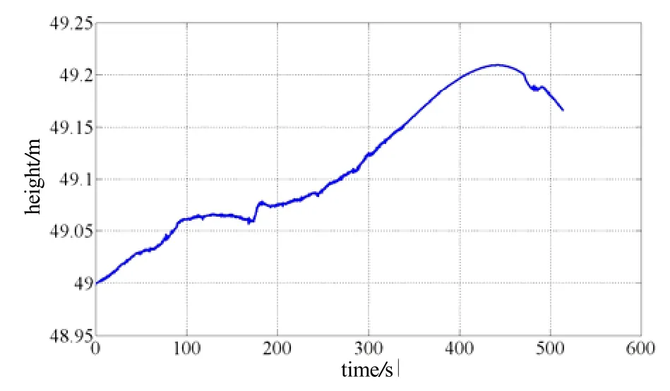
Fig.13 Height of integared navigation system withnot Kalman filter
The polarization navigation sensor/MIMU/odometer are used to complete navigation, and the Kalman filter is used to estimate the error, and then the feedback is used to compensate the error. Some data are better than those without using Kalman filter. There is basically no drift in yaw angles, and the eastward velocity and the northward velocity drifts are little after using the Kalman filter.From the error estimation, we know that the fluctuation range of the yaw angle is less than 0.3°, which improves the stability of the system. By using the Kalman filter (Fig.16 and Fig.17), the integrated navigation system can correctly calculate the velocity, the position also can be calculated correctly by comparing with Fig.6.
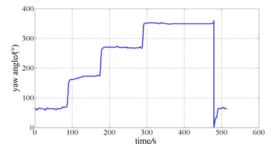
Fig.14 Yaw angle of integated navigation system with Kalman filter
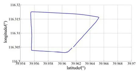
Fig.15 Position of integated navigation system with Kalman filter
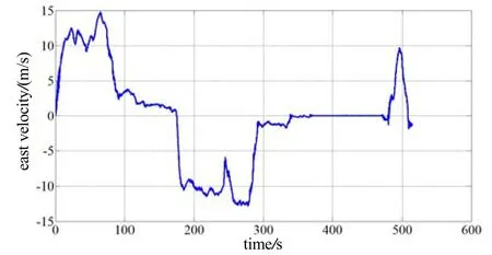
Fig.16 Eastward velocity of integared navigation system with Kalman filter
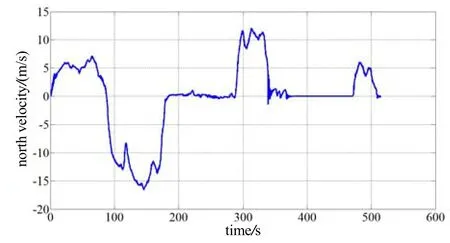
Fig.17 Northward velocity of integated navigation system with Kalman filter
3 Conclusion
Based on the data and simulation, this paper verifies that IIR low-pass filter can eliminate some unnecessary noises since the data’s mean square roots of the MEMS sensor using IIR low-pass filter are better than those without using it. The polarization navigation sensor provides the initial yaw angle which can help MIMU accomplish the initial alignment. In navigational state, an odometer can be used to provide horizontal velocity and formed integrated navigation system with MIMU.
According to measured data, the attitude angle drifts are obvious when MIMU update attitudes and velocities are in the absence of polarization navigation sensor. If MIMU is with the assistant of polarization navigation sensor and odometer, which provide yaw angle and horizontal velocity, the divergences of yaw angle and horizontal velocity can be avoided effectively. When using Kalman filter to compensate the measured data, the precision of yaw angle can be further improved. The Kalman filter can also effectively suppresses the divergence of horizontal velocity, and the integrated navigation system is in close proximity to real velocity and position of the experiment, with the divergence of position being less than 1% of total mileage.
[1] Knaden M, Wehner R. Ant navigation: resetting the path integrator[J]. The Journal of Experimental Biology, 2006, 209: 26-31.
[2] Lambrinos D, Miller R, Labhart T, et al. A mobile robot employ insect strategies for navigation[J]. Robotics and Autonomous systems, 2000, 30(1): 39-64.
[3] 祝燕华, 蔡体菁, 李春, 等. 天空偏振光辅助的组合导航方法[J]. 中国惯性技术学报, 2012, 20(6): 674-677. Zhu Yan-hua, Cai Ti-jing, Li Chun, et al. Integrated navigation method aided by skylight polarization[J]. Journal of Chinese Inertial Technology, 2012, 20(6): 674-677.
[4] 李荣冰, 于永军, 刘建业, 等. 大气辅助的SINS/GPS组合导航系统研究[J]. 仪器仪表学报, 2012, 33(9): 1961-1966. Li Rong-bing, Yu Yong-jun, Liu Jian-ye, et al. Research on SINS/GPS integrated navigation system with air data system[J]. Chinese Journal of Scientific Instrument, 2012, 33(9): 1961-1966.
[5] 陈家斌, 关桂霞, 李磊磊, 等. 偏振光导航[J]. 导航与控制学报, 2014, 13(1): 57-63. Chen Jia-bin, Guan Gui-xia, Li Lei-lei, et al. Polarization navigation[J]. Navigation and Control, 2014, 13(1): 57-63.
[6] Badri A E, Sinha J K, Albarbar A, et al. A typical filter design to improve the measured signals from MEMS accelerometer[J]. Measurement, 2010, 43(10): 1425-1430.
[7] Angrisano A, Petovello M, Pugliano G, et al. Benefits of combined GPS/GLONASS with low-cost MEMS IMUs for vehicular urban navigation[J]. Sensors, 2012, 12(4): 5134-5158.
[8] Noureldin A, El-Shafie A, Bayoumi M, et al. GPS/INS integration utilizing dynamic neural networks for vehicular navigation[J]. Information Fusion, 2010, 12(1): 48-57.
[9] Ali J, Mirza M R U B. Performance comparison among some nonlinear filters for a low cost SINS/GPS integrated solution[J]. Nonlinear Dynamics, 2010, 61(3): 491-502.
[10] 张阳, 景占荣. 基于MEMS-SINS/GPS的组合导航系统设计[J]. 计算机测量与控制, 2011, 19(9): 2282-2285. Zhang Yang, Jing Zhan-rong. Design of MEMS-SINS/ GPS integrated navigation system[J]. Computer Measurement & Control, 2011, 19(9): 2282-2285.
偏振光传感器与微惯性器件组合导航技术
李磊磊,刘 凯,陈家斌,刘慧亚,杨黎明
(北京理工大学 自动化学院,北京 100081)
微惯性系统由于成本低,可靠性高,尺寸小等等优点成为目前研究的热点。但是微惯性系统不能提供正确的航向角,所以无法单独完成初始对准。而仿生偏振光传感器通过计算可得到航向角,并且偏振光传感器的误差不发散可以抑制微惯性器件的误差发散,所以把偏振光传感器和微惯性系统进行组合有很多优点。实验结果验证了偏振光导航传感器的数据是不发散的,并根据偏振光导航传感器提供的航向角完成了初始对准。在导航状态中,里程计用来提供水平速度,并通过卡尔曼滤波将偏振光导航传感器、微惯性系统和里程计组合。最后,通过实验验证了该组合导航系统的可行性。
偏振光导航;微惯性系统;卡尔曼滤波;初始对准;里程计
U666.1
A
1005-6734(2015)02-0219-05
2014-11-26;
2015-03-02
国家国防基金(9140A09050313BQ01127);国家自然科学基金(91120010)
李磊磊(1978—),男,博士,讲师,研究方向为导航、制导与控制。E-mail:lileilei@bit.edu.cn
10.13695/j.cnki.12-1222/o3.2015.02.015
猜你喜欢
物理教师(2022年12期)2023-01-16
导航定位学报(2022年5期)2022-10-13
空间电子技术(2020年5期)2020-03-11
中国惯性技术学报(2019年1期)2019-05-21
当代陕西(2018年12期)2018-08-04
现代职业教育·中职中专(2018年11期)2018-06-11
中国惯性技术学报(2017年1期)2017-06-09
电脑知识与技术(2016年20期)2016-08-19
导航定位与授时(2016年6期)2016-03-16
弹箭与制导学报(2016年5期)2016-03-02
