
UAV Velocity Measurement for Ground Moving Target
2015-11-21 07:08HuangDaqing黄大庆XuCheng徐诚HanWei韩伟WangDongzhen王东振
关键词:大庆
Huang Daqing(黄大庆),Xu Cheng(徐诚),Han Wei(韩伟),Wang Dongzhen(王东振)
1.Research Institute of UAV,Nanjing University of Aeronautics and Astronautics,Nanjing 210016,P.R.China;
2.College of Electronic and Information Engineering,Nanjing University of Aeronautics and Astronautics,Nanjing 210016,P.R.China
UAV Velocity Measurement for Ground Moving Target
Huang Daqing(黄大庆)1*,Xu Cheng(徐诚)1,Han Wei(韩伟)2,Wang Dongzhen(王东振)2
1.Research Institute of UAV,Nanjing University of Aeronautics and Astronautics,Nanjing 210016,P.R.China;
2.College of Electronic and Information Engineering,Nanjing University of Aeronautics and Astronautics,Nanjing 210016,P.R.China
To satisfy the demand of measuring the velocity of ground moving target through unmanned aerial vehicle
unmanned aerial vehicle(UAV);target velocity measurement;target localization;velocity measurement error
0 Introduction
Compared with the manned aircraft,unmanned aerial vehicle(UAV)has the advantages of small size,low cost,convenient operation,low requirement for environment,etc.Therefore,UAV has been widely applied to various fields,including reconnaissance,surveillance,emergency rescue,disaster relief and so on[1-2].
UAV optical target localization is to calculate the position of ground target with the combination of UAV navigation information,the electrooptical platform pointing angle and the ranging information.Lots of researchers in domestic and abroad have investigated and discussed the new method of UAV target localization and the target localization accuracy improvement[3-6].
With the development of science and technology,the ground target location can no longer meet the demand of comprehensive and dynamic information.Therefore,using photoelectric technology to measure the speed of ground targets from the air has become increasingly necessary. In the traditional method,airborne radar,which utilizes the Doppler effect,is adopted to measure the ground target velocity.When a target is close to the radar antenna,the reflected signal frequency will be higher than the transmitter frequency. However,when it is far from the antenna,the reflection signal frequency will be lower than the transmitter frequency.According to the frequency chang,the relative velocity of target and radar can be measured[7].Hence,the target velocity measurement based on photoelectric technology is superior to the conventional radar velocity measurement thanks to its high sensitivity,easy self stealth and so on.It can be used as an effective supplement to radar velocity measurement.
A novel technology for UAV moving target velocity measurement is proposed in this paper.Eirst,a velocity measurement method based on target localization is presented,which is easy to be deployed and realized.Then a mathematical model for measuring target velocity is established,consisting of 15 variables,such as UAV velocity,UAV attitude angular rate,and camera pointing angular rate.Besides,the causes of velocity measurement error is analyzed and the formula is derived for calculating the measurement error.The experimental results show that the method is correct and effective with promising application prospect.
1 System Structure and Coordinate Definition
1.1 Overall system structure
Here,the UAV target velocity measurement system is equipped with GPS,inertial navigation system,and electro-optical platform.Airborne electro-optical platform is installed in the aircraft with upside down.During flight,the position and attitude of UAV always change[8].The stable tracking function of electro-optical platform can insulate the jitter of optic axis in inertial space which is caused by UAV attitude motion and other disturbance torque.Image tracker of electrooptical platform will initiate tracking when it finds an interesting target image.It can keep the target in the center of camera view field to realize stable tracking,as shown in Eig.1.
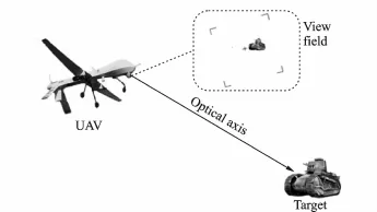
Eig.1 Target velocity measurement system
1.2 Coordinate definition
Eirst we define the following coordinate systems[9-11]:
(1)Geodetic coordinate system
In a geodetic coordinate system,the coordinate origin is the earth′s center,Zoaxis points to the north direction,and Xoaxis to the intersection direction of the Greenwich meridian plane and the earth′s equator.In the geodetic coordinate system,the coordinate of each point can be expressed as(B,L,H),where B,L,H represent latitude,longitude and height of the point respectively.
(2)Geodetic rectangular coordinate system
A geodetic rectangular coordinate system overlaps the geodetic coordinate system.Each point coordinate in the geodetic rectangular coordinates system can be expressed by the projection of the point to each coordinate axis(xg,yg,zg).
(3)Geographic coordinate system
In a geographic coordinate system,the coordinate origin is the aircraft center.Znaxis points to the north direction,and Xnaxis to the sky,as shown in Eig.2.In the geographic coordinate system,each point can be expressed as(xn,yn,zn).
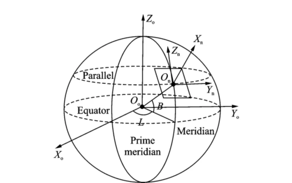
Eig.2 Coordinate system definition
(4)Aircraft coordinate system
In an aircraft coordinate system,the coordinate origin is the aircraft center.Ybrepresents the horizontal axis of the aircraft,and Zbthe vertical axis of the aircraft,Xbpoints to the back from abdomen of the aircraft.The heading angle,the pitch angle and the roll angle of the aircraft represent the three axis attitudes of the coordinate system relative to the geographic coordinate sys-tem.When all the attitude angles are zero,the aircraft coordinate system and the geographic coordinate system overlap.In the aircraft coordinate system,coordinate of each point can be expressed as(xb,yb,zb).
(5)Camera coordinate system
In a camera coordinate system,the coordinate origin is the intersection of camera optical axis and horizontal axis.Xcaxis is camera optical axis pointing to the target.The optical axis pointing angle can be expressed by azimuth angleαand elevation angleβ.
2 Velocity Measurement Based on Target Localization
Target localization is a process to obtain three-dimensional coordinates of the target.The UAV target localization system can output the coordinates of the target in the geodetic coordinate system,namely latitude,longitude and height.
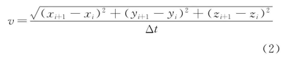
Given the position data(Bi,Li,Hi)and(Bi+1,Li+1,Hi+1)of a target at the moment Tiand Ti+1respectively,the target position data are transformed to(xi,yi,zi)and(xi+1,yi+1,zi+1)in the geodetic rectangular coordinate.The conversion process can be expressed as[12]
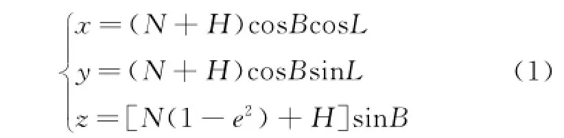

In the interval ofΔt=Ti+1-Ti,the average velocity of moving target is
Though the method is based on the target localization,which is easy to utilize in the existing target localization system,it does not consider the essence of target localization and introduces redundant coordinates conversion.The target localization process based on electro-optical platform is shown in Eig.3,which is essentially a coordinate conversion process from the camera coordinate system to the geodetic coordinate system. During the process,there exists a conversion from the geodetic rectangular coordinate to the geodetic coordinate system.Moreover,in the target velocity measurement process,there is a conversion from the geodetic coordinate to the geodetic rectangular coordinate system.Clearly the above two transformations are redundant,thus bringing forth redundant computing consumption and causing a decline in velocity measurement accuracy.

Eig.3 Process of target localization
3 Target Velocity Measurement Based on Pointing Angle Change
Macroscopically,when the moving target is tracked steadily by UAV,the change of UAV position,attitude and target position is the fundamental reason for the camera pointing angle change.It also shows that the parameters,including UAV velocity,attitude rate,camera pointing angle rate,and target velocity satisfy a mathematical relation,from which the target velocity measuring method can be derived.
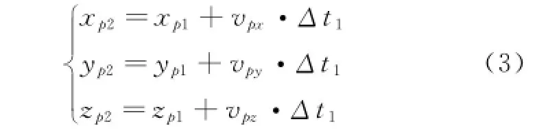
In Eig.4,UAV observes the moving target at P1,P2respectively.M1,M2are the target positions at time T1,T2,respectively.Eor simplicity,the auxiliary coordinate system O-XnYnZnis established,wherein,Xnpoints to the zenith,Ynthe east,and Znthe north.P1-Xn1Yn1Zn1and P2-Xn2Yn2Zn2are the geographic coordinate systems of P1and P2respectively.Besides,the axes of coordinate system O-XnYnZn,P1-Xn1Yn1Zn1,P2-Xn2Yn2Zn2are parallel to each other.Set vmx,vmyand vmzas the three-axis components of the air-craft average velocity in the time intervalΔt1= T2-T1.(xp1,yp1,zp1)is the coordinates of P1in the O-XnYnZn;(xp2,yp2,zp2)the coordinates of P2in the O-XnYnZn;(xm1,ym1,zm1)the coordinate of M1in the O-XnYnZn;and(xm2,ym2,zm2)the coordinate of M2in the O-XnYnZn.
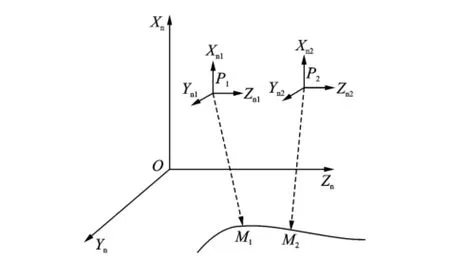
Eig.4 Principle of target velocity measurement
Let(xnm1,ynm1,znm1)be the coordinates of M1in the P1-Xn1Yn1Zn1,(xnm2,ynm2,znm2)as the coordinate of M2in the P2-Xn2Yn2Zn2.
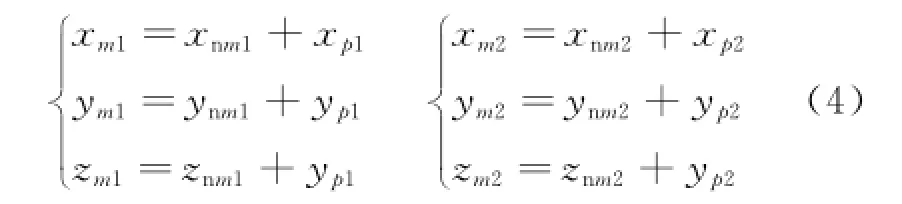
Combined Eq.(3)with Eq.(4),the average velocity of moving target can be derived in the time intervalΔt1=T2-T1.

Thus
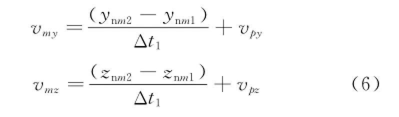
Generally,the average velocity of moving target can be written in the time intervalΔti=Ti+1-Tias
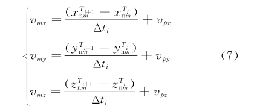
WhenΔtiis infinitesimal,Eq.(7)can be written approximately as follows
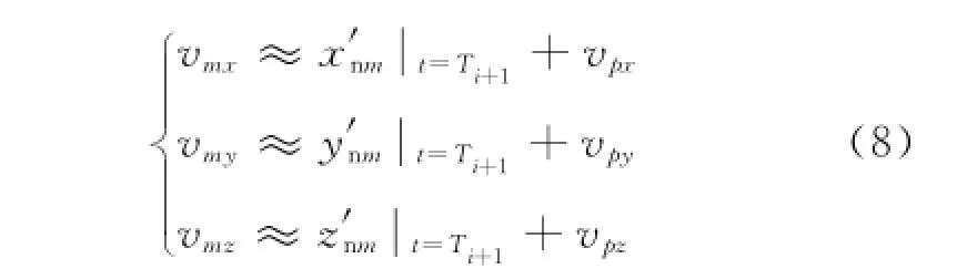
where x′nm,y′nm,z′nmare the derivations of xnm,ynm,znmat time t,respectively.Thus,the average velocity of moving target is derived in the time intervalΔti.In Eq.(8),vpx,vpy,vpzcan be measured directly,but x′nm,y′nm,z′nmcannot. However,they can be obtained by calculation.
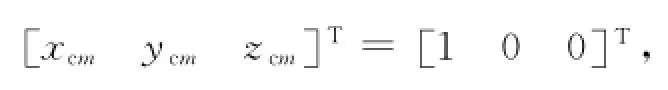
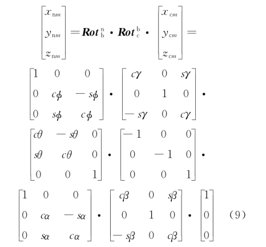
According to Eq.(11)and Eq.(8),the target velocity is related to the following variables: aircraft heading angleφ,pitch angleγ,roll angle θ,camera azimuth angleαand elevation angleβ,laser ranging value r,aircraft heading angle rate φ′,pitch angle rateγ′,roll angle rateθ′,camera azimuth angle rateα′,elevation angle rateβ′,and laser ranging change rate r′.To simplify description,the aircraft heading angle rateφ′is defined asωφ,the pitch angle rateγ′asωγ,the roll angle rateθ′asωθ,the camera azimuth angle rateα′as ωα,the elevation angle rateβ′asωβ,and the laser ranging value rate r′as vr.Therefore,the X axis velocity component of the moving target can be written as
where s(·)is short for sin(·)and c(·)for cos(·).After the expansion and simplification of Eq.(9),Eq.(10)can be acquired.Eurthermore,Eq.(11)can be obtained from the derivation of xnmon t.Similarly,the mathematical expressions of y′nmand z′nmare known.
In Eq.(11),the heading angle rateφ′,the pitch angle rateγ′and the roll angle rateθ′can be measured by aircraft navigation system,the azimuth angle rateα′and elevation angle rateβ′can be measured by the angular velocity sensor of electro-optical platform,and the laser ranging value rate r′can be calculate by two times laser ranging measurement combined with the measurement interval.In practice,the above measurement of each rate should be in a same time period
After the previous derivation,the source of target velocity measurement error includes aircraft attitude angle error(Δφ,Δγ,Δθ),aircraft attitude angle rate error(Δωφ,Δωγ,Δωθ),camera pointing angle error(Δα,Δβ),camera pointing angle rate error(Δωα,Δωβ),laser ranging value errorΔr,laser ranging value rateΔvr,and velocity error of the aircraft(Δvpx,Δvpy,Δvpz).
The target velocity measurement error can be obtained by perfect differential.Taking the solution of moving target velocity error on the X axis for example,partial derivative for each variable respectively will get Eq.(13).Combined Eq.(12)with Eq.(13),the specific velocity error can be acquired.The solutions ofΔvmyandΔvmzare the same as that ofΔvmx.Thus,the velocity error of moving target can be calculated by Eq.(14).
4 Simulation Results
The motion laws of target and aircraft are first established,which are much close to the real condition.Then the target coordinates and air-craft coordinates can be created.Considering that each measured parameters bring errors in practice,it also need to add different noise to these parameters.Then,using the proposed method,the average velocity of moving targets in different times can be calculated.Compared with the located velocity of moving target in simulation,the correctness and the accuracy of the method is validated.
The simulation condition can be expressed as
where(xp,yp,zp)is the aircraft trajectory and(xm,ym,zm)the target trajectory.It is assumed that the measurement parameter error obeys Gauss distribution.The errors of aircraft attitude angle(heading angle,pitch angle,roll angle)and attitude angle rate are 0.3°and 0.1°/s,respectively.The errors of camera pointing angle(azimuth,angular altitude and direction angle rate are 0.02°and 0.01°/s,respectively.The error of laser ranging is 5 m,the error of laser ranging rate 5 m/s,and the error of aircraft velocity 5 m/s.
Measuring the velocity every 0.5 s,100 groups of velocity values be acquired.By repeating simulation calculation of each velocity value for 1 000 times,the final measured velocity of the target is obtained.Eig.5 shows the distribution of measured velocity and actual velocity of the target point duration in 50 s.The measured velocity and actual velocity of moving target are basically coincide,it proves that the target velocity measurement algorithm proposed in this paper can measure the velocity of moving targets effectively.

Eig.5 Simulation results
Eurthermore,two simulation are conducted to study the effect of angular rate measurement errors on measurement precision.
(1)With the increasing aircraft attitude angle rate error(Δωφ,Δωγ,Δωθ)from 0°to 0.5°,the rest of the measurement errors are all zero. The experimental results are demonstrated in Eig.6.Here,the aircraft pitch angular rate error and roll angular rate error have higher impact on target velocity measurement accuracy.Along with the increase of pitch angle rate error and roll angular rate error,velocity error also increases rapidly.Besides,the influence of heading angle rate error on the target measured velocity accuracy is relatively small.
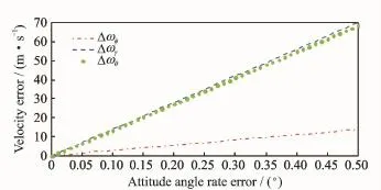
Eig.6 Relation between attitude angular rate error and velocity error
(2)When the camera pointing angle rate error(Δωα,Δωβ)varies from 0°to 0.05°,the rest of the measurement errors are all zero.In Eig.7,the influence of elevation angle rate error is obviously stronger than the azimuth angle rate error on the target measuring velocity accuracy.
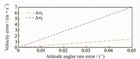
Eig.7 Camera pointing angular rate error v.s.velocity error
Erom the two experiments mentioned above,the following conclusions can be drawn.In the process of UAV target measured velocity,angle rate measured error(Δωφ,Δωγ,Δωθ,Δωα,Δωβ)has larger effect on the target measuring velocity accuracy,especially the aircraft pitch angle rate errorΔωγ,the roll angular rate errorΔωθ,and the camera elevation angle rate errorΔωβ.Therefore the increase of measuring precision of angular rate is an effective way to improve the measurement accuracy of target velocity.
5 Conclusions
Two methods using electro-optical platform of UAV are proposed for velocity measurement. Eirst,an easy velocity measurement method based on target localization is derived,using the position difference between two points.Then a mathematical model for measuring target velocity is established based on 15 variables,including UAV velocity,UAV attitude angular rate,camera pointing angular rate and so on.Besides,the causes of velocity measurement error are analyzed and a formula is derived to calculate the measurement error.The experimental results show that it is feasible and effective to use electro-optical platform and UAV navigation data in velocity measurement of moving target,which provides a new approach to velocity measurement of UAV relative to ground target.
Acknowledgement
This work was supported by the Aeronautical Science Eoundation of China(No.61106018).
[1] Han K,Aeschliman C,Park J,et al.UAV vision: Eeature based accurate ground target localization through propagated initializations and interframe homographies[C]∥Robotics and Automation(ICRA),2012 IEEE International Conference on.[S.l.]: IEEE,2012:944-950.
[2] Kwon H,Pack D J.A robust mobile target localization method for cooperative unmanned aerial vehicles using sensor fusion quality[J].Journal of Intelligent &Robotic Systems,2012,65(1/2/3/4):479-493.
[3] Morbidi E,Mariottini G L.Active target tracking and cooperative localization for teams of aerial vehicles[J].Control Systems Technology,IEEE Transactions on,2013,21(5):1694-1707.
[4] Lin E,Dong X,Chen B M,et al.A robust real-time embedded vision system on an unmanned rotorcraft for ground target following[J].Industrial Electronics,IEEE Transactions on,2012,59(2):1038-1049.
[5] Quigley M,Goodrich M A,Griffiths S,et al.Target acquisition,localization,and surveillance using a fixed-wing mini-UAV and gimbaled camera[C]∥IEEE International Conference on Robotics and Automation.Barcelona:IEEE,2005:2600-2605.
[6] Tisdale J,Ryan A,Kim Z,et al.A multiple UAV system for vision-based search and localization[C]∥American Control Conference.Washington:IEEE,2008:1985-1990.
[7] Liu L,Li Y.Velocity estimation algorithm for traffic surveillance radar based on autofocus[J].Journal of Nanjing University of Aeronautics&Astronautics,2013,45(6):843-848.(in Chinese)
[8] Sun M C,Liu J H,Zhang B,et al.Design of measuring gondola system with high frame rate for image fusion[J].Optics and Precision Engineering,2013,21(1):94-100.(in Chinese)
[9] Rafi E,Khan S,Shafiq K,et al.Autonomous target following by unmanned aerial vehicles[C]∥Defense and Security Symposium.Orlando:International Society for Optics and Photonics,2006:623010-623010-8.
[10]Dogancay K.UAV path planning for passive emitter localization[J].Aerospace and Electronic Systems,IEEE Transactions on,2012,48(2):1150-1166.
[11]Hmam H,Dogancay K.Passive localization of scanning emitters[J].Aerospace and Electronic Systems,IEEE Transactions on,2010,46(2):944-951.
[12]Huang Lei,Liu Jianye,Zeng Qinghua.Optimized strapdown coning correction algorithm[J].Transactions of Nanjing University of Aeronautics and Astronautics,2013,30(4):343-349.
(Executive editor:Zhang Tong)
V249 Document code:A Article ID:1005-1120(2015)01-0009-07
*Corresponding author:Huang Daqing,Researcher,E-mail:radiouav@sina.com.
How to cite this article:Huang Daqing,Xu Cheng,Han Wei,et al.UAV velocity measurement for ground moving target[J].Trans.Nanjing U.Aero.Astro.,2015,32(1):9-15.
http://dx.doi.org/10.16356/j.1005-1120.2015.01.009
(Received 20 November 2014;revised 16 December 2014;accepted 12 January 2015)
(UAV)electro-optical platform,two velocity measurement methods are proposed.Eirstly,a velocity measurement method based on target localization is derived,using the position difference between two points with the advantages of easy deployment and realization.Then a mathematical model for measuring target velocity is built and described by 15 variables,i.e.UAV velocity,UAV attitude angular rate,camera direction angular rate and so on. Moreover,the causes of velocity measurement error are analyzed and a formula is derived for calculating the measurement error.Einally,the simulation results show that angular rate error has a strong influence on the velocity measurement accuracy,especially the UAV pitch angular rate error,roll angular rate error and the camera angular altitude rate error,thus indicating the direction for improving velocity measurement precision.
猜你喜欢
青年文学家(2020年28期)2020-11-02
传媒评论(2019年12期)2019-08-24
小小说月刊(2018年4期)2018-03-20
——高大庆作品欣赏
陶瓷科学与艺术(2018年12期)2018-02-19
艺术家(2017年2期)2017-11-26
东北史地(学问)(2017年1期)2017-06-15
知与行(2017年3期)2017-03-30
声屏世界(2015年8期)2015-02-28
中国火炬(2014年9期)2014-07-25
重庆与世界(2012年12期)2012-08-14
 Transactions of Nanjing University of Aeronautics and Astronautics2015年1期
- Transactions of Nanjing University of Aeronautics and Astronautics的其它文章
- CRB for 2-D DOA Estimation in MIMO Radar with UCA
- Flight Dynamic Analysis of Hypersonic Vehicle Considering Liquid-Solid Coupling
- Tradeoff Analysis of Factors Affecting Longitudinal Carrier Landing Performance for Small UAV Based on Backstepping Controller
- Improved Shuffled Frog Leaping Algorithm Optimizing Integral Separated PID Control for Unmanned Hypersonic Vehicle
- Beamforming of Whole Airspace Phased Array TT&C System Based on Linear Subarrays
- Trim Drag Prediction for Blended-Wing-Body UAV Configuration