
Long-term dynamic behavior of monopile supported offshore wind turbines in sand
2015-11-21 08:48LuQingYuLiZhongWngZhenGuoBhtthryNikitsLingLingLiYueLongXing
Lu-Qing Yu,Li-Zhong Wng,Zhen Guo,S.Bhtthry,G.Nikits,Ling-Ling Li,Yue-Long Xing
aResearch Center of Coastal and Urban Geotechnical Engineering,Zhejiang University,Hangzhou 310058,China
bZhejiang Electric Power Design Institute,Zhejiang,Hangzhou 310012,China
cUniversity of Surrey,Department of Civil and Environmental Engineering,Guildford,Surrey GU2 7XH,UK
Long-term dynamic behavior of monopile supported offshore wind turbines in sand
Lu-Qing Yua,b,Li-Zhong Wanga,∗,Zhen Guoa,S.Bhattacharyac,G.Nikitasc,Ling-Ling Lia,Yue-Long Xingb
aResearch Center of Coastal and Urban Geotechnical Engineering,Zhejiang University,Hangzhou 310058,China
bZhejiang Electric Power Design Institute,Zhejiang,Hangzhou 310012,China
cUniversity of Surrey,Department of Civil and Environmental Engineering,Guildford,Surrey GU2 7XH,UK
A R T I C L E I N F O
Article history:
Received 23 October 2014
Accepted 29 December 2014
Available online 14 March 2015
Offshore wind turbine
Long-term
Dynamic behavior
Strain accumulation
Similitude
The complexity ofthe loads acting on the offshore wind turbines(OWTs)structures and the significance of investigation on structure dynamicsare explained.Testresults obtained froma scaled wind turbine model are also summarized.The modelis supported on monopile,subjected to differenttypes ofdynamic loading using an innovative out of balance mass system to apply cyclic/dynamic loads.The test results show the natural frequency of the wind turbine structure increases with the number of cycles,but with a reduced rate of increase with the accumulation of soil strain level.The change is found to be dependent on the shear strain level in the soil next to the pile which matches with the expectations from the element tests of the soil.The test results were plotted in a non-dimensional manner in order to be scaled to predict the prototype consequences using element tests of a soil using resonant column apparatus.
©2015 The Authors.Published by Elsevier Ltd on behalf of The Chinese Society of Theoretical and Applied Mechanics.This is an open access article under the CC BY license(http://creativecommons.org/ licenses/by/4.0/).
Introduction Harvesting offshore wind energy is a new initiative and a promising option for protecting the environment.Offshore wind turbines(OWTs)are relatively new structures with no long term track record of their performance yet they are to be constructed and meant to produce energy for 25-30 years[1-4]. OWTs,due to their slender nature coupled with irregular mass and stiffness distribution,are dynamically sensitive structures.The first natural frequencies of these structures are very close to the forcing frequencies imposed by the environments and the onboard machinery.Changes of the foundation stiffness under cyclic loading will ultimately result in changes to the natural frequency of the structure.Therefore,the design of foundations and prediction of long term performance are very challenging.The loading on an OWT is complex and is a combination of static,cyclic,and dynamic loads:
(1)the external load produced by the wind and its turbulence,applying approximately one-way cyclic load to the foundation,
(2)the external load caused by waves,which is approximately two-way cyclic,
(3)the internalload caused by the vibration at the hub leveldue to the mass and aerodynamic imbalances of the rotor(this load has a frequency equal to the rotational frequency of the rotor(referred to as 1P loading in the literature)and is dynamic in nature),
(4)dynamic internal loads on the tower(as shown in Fig.1)due to the vibrations caused by blade shadowing effects(referred to as 2P/3P in the literature),which is dynamic in nature.
Typical natural frequencies of OWTs are in the range of 0.3-0.9 Hz[1].The load frequencies that are close to the natural frequency of the turbines can be classified as dynamic load which requires special consideration,i.e.,the ratio of forcing frequency to natural frequency(ff/fn)and the damping in the system.
A case study Shanghai Donghai Bridge offshore wind farm is one of the first large scale commercial developments[5].Figure 2 shows the main frequencies for a three-bladed 3 MW Sinovel wind turbine with an operational interval of 8.1-19 RPM(revolutions per minute).The 1P lies in the range 0.135-0.316 Hz and the corresponding 3P lies in the range 0.405-0.948 Hz.The figure also shows typical frequency distributions for wind and wave loading. The peak frequency of typical waves is about 0.12 Hz.It is clear fromthe frequency contentofthe applied loads thatthe designer of the turbine and foundation has to select a system frequency which lies outside this range of frequencies in order to avoid system resonance and ultimately increased fatigue damage.
Three types of designs are possible(see Fig.2):(1)‘‘soft-soft’’design,where the target frequency is placed below the 1P frequency range,i.e.,less than 0.135 Hz,which is a very flexible structure and almost impossible to design for a grounded system,(2)‘‘softstiff’’design,where the target frequency is between 1P and 3P frequency ranges and this is the most common in the current offshore development,(3)‘‘stiff-stiff’’design,where target natural frequency have a higher natural frequency than the upper limit of the 3P band and willneed a very stiffsupportstructure.Det Norske Veritas(DNV)[6]also specified that the system frequency should be at least±10%away from operational 1P and 2P/3P frequencies,as indicated by the dotted lines in Fig.2.Therefore,the available range of safe frequency content to place the OWT is narrow.
Prediction of OWT’s long term behavior OWTs are subjected to approximately 107-108cycles of loading in their life time and two aspects are important with regards to the design of foundations:(1)assessment of the change of soil behavior due to effect of cycling and its impact on the foundation(this is similar to the fatigue problem)and(2)dynamic amplification ofthe response of the structure over a range of excitation frequencies close to the natural frequency of the system.This would mean higher displacement of the foundation,i.e.,higher strain in the soil.This is similar to the resonance problem.Recent observations of wind turbines suggest that resonance is a serious issue[7-10].Field measurement indicates that the resonance issue is caused by the change of its foundation stiffness after several years of service[2].
Therefore,the design problems are:(1)prediction of the long term tilt in the wind turbine due to the change in the soil properties owing to irregular and asymmetric cycling,(2)long term shift in naturalfrequency ofthe systemand how close can the frequency be with respect to the forcing frequencies.This is particularly important for‘‘soft-stiff’’design as any increase/decrease will impact on the forcing frequency causing higher fatigue damage[11].
Due to its previous successful application in OWTs,monopile is still the prevailing foundation option for supporting OWT for water depth of less than 30 m in standard soils(sand,soft and stiff clay).More than 75%of the OWTs in Europe(i.e.,UK,Denmark,Germany,and Netherlands)are supported on monopiles[1].This paper therefore investigates the long-term dynamic behavior of monopile supported OWT through a series of small scale tests.This is in contrast to the tests carried out in other researchers’work,see for example Refs.[12,13],where the dynamics ofthe problemis not considered and fatigue type problem is investigated.
Derivation of the correct scaling laws constitutes the first step in an experimental study.Every physical process or mechanism can be expressed in terms of non-dimensional groups and the fundamental aspects of physics must be preserved in the design of model tests.In this paper,the main principle of scaling related to OWTs comprises of geometrical and mechanical similarities between scaled model tests and prototype.And this part has been discussed in detail in Refs.[1,14,15]and the readers can refer to those publications for more information.
Dynamic loading system Previous research[1,14-16]on dynamic testing as shown in Fig.3(a)used an actuator to apply all the cyclic and dynamic loads atone location(denoted by ycin Fig.3(b))and the methodology to find out the load is shown in Fig.3(b)[1]. After applying a user defined number of cycles,the actuator is disconnected to obtain the natural frequency through free vibration test.Then,the actuator needs to be reconnected to apply the next set of cyclic loads.This causes not only some amount of inconvenience to the testing but also unavoidable disturbance to the soil around the foundation.Furthermore,the actuator can only provide one directional regular cyclic loads.But in reality,due to the misalignment of wind and wave,the cyclic load is always multidirectional.This led to the development of an innovative cyclic loading system used in this paper.
The physics behind this innovative device is simple and follows the concepts of centripetal forcing,i.e.,for a body of mass m,which is rotating about a center in a circular arc of radius r at a constant angular frequencyω,the mass will exert an extra force acting towards the center of rotation in the magnitude of Fn(Fn=mrω2,see Fig.4(a)).Figure 4(b)shows the final design of the device and itproducesa harmonic loading in two perpendicular directions when two masses(m1and m2)complete one revolution(shown in Figs.4(c)and 4(d)).Thus,the simple and economic device is comparable to an actuator,but with an obvious advantage of producing two directional two-way cyclic loading,which indicates a misalignment of wind and wave in real field.The frequency ff(Hz)of the applied loads is determined by the voltage U(V)that drives the motor of the device.The amplitude and frequency of the cyclic loads can be adjusted by replacing the masses(m1and m2)on the gears and the voltage output.
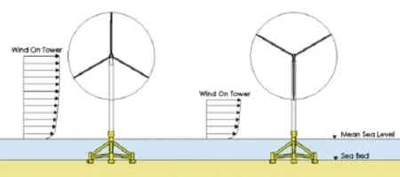
Fig.1.Cyclic/dynamic load acting on the tower due to blade shadowing effect.

Fig.2.Forcing frequencies against the power spectral densities for a 3 bladed 3 MW Sinovel OWT.

Fig.3.(a)An actuator used to supply dynamic loads.(b)The method to compute the load P and height yc.
Test preparation and procedures Dynamic tests are carried out in a model tank(1150 mm long,950 mm wide,and 600 mm high). The soil used in this experiment is Red Hill 110 silica sand,which is quite typical of that encountered in the North Sea,and it is representative of the soil along the southeast coastline of China[3]. Some basic properties of this sand is given is Table 1.The sand bed is prepared by pouring sand from a hopper,maintaining the same rate of flow and the same height.The final thickness of the sand bed is approximately 500 mm.Relative density of the sand bed is 63%as medium dense sand.Shear modulus of the sand bed G is obtained as approximately 10 MPa by the in-situ shear wave velocity method.Based on the scaling laws,set-up of the experiment is shown in Fig.5.The model turbine mainly consists of 3 parts,more detailed information is given in Table 2.The innovative cyclic loading device is connected to a volt generator,and mounted on top of the tower.A set of micro electro mechanical system(MEMS)accelerometer[17]is used to obtain the naturalfrequency and damping during the free vibration testing.The tests were carried out in the following procedures.
(1)Before the cyclic loading is applied,a small amplitude free vibration test is performed,and the response signal is recorded in the time domain by accelerometers to obtain the initial natural frequency of the system.

Fig.4.(a)Circular motion of a mass point.(b)Out-of-balance mass system.(c)Sketch of the principles.(d)The resultant forces in X and Y directions.

Fig.5.Photo of the test set-up.

Table 1Properties of the red hill silica sand.

Table 2Detailed parameters of the model turbine.
(2)The model turbine is then subjected to cyclic loading for a chosen time of interval(typically 5000 cycles)with a certain levelof frequency and amplitude.The dynamic property is then evaluated atthe end ofthe chosen number ofcycles through another free vibration test.This operation is repeated until sufficient number of cycles was reached and a trend is established.
(3)Another set of test under different cyclic loading is conducted by adjusting m1and m2in the gear system and the output voltage.
Four groups of tests are performed on the 1:100 scaled wind turbine model,aiming to study the long-term dynamic behavior of monopile supported model in sand.The investigation focuses on the influence from the amplitude of cyclic loads.Bhattacharya et al.[14]showed that the ratio of forcing frequency to natural frequency(ff/fn)is close to 1 in field,so the dynamic effects from the exciting loads is also considered by setting ff/fnas 1.302.It is subjected up to 196,515 cycles,and the innovative cyclic loading device is used to apply one directional single frequency cyclic loads on the model turbine,but with different forcing amplitudes,corresponding to different non-dimensional P/GD2and M/GD3,where P is lateral load in the foundation,M is the mudline bending moment,G is the shear modulus of the soil,and D is the pile diameter.Lombardi et al.[1]showed that P/GD2and M/GD3represents the shear strain in the soil around the pile.Throughout the tests,m1=m2is maintained,detailed information about all of the tests is given in Table 3.
Test results and interpretation Figure 6(a)shows a typical time domain acceleration signal recorded by the accelerometer during the free vibration test.Assessment of the model turbine’s natural frequency is performed in the frequency domain using the Welch method[19],and the result is given in Fig.6(b).The first two peaks in Fig.6(b)correspond to the first two orders of natural frequency of the model structure.
Changes of the 1st natural frequency(fn/fn-initial)of the system with respect to the number of cycles(N)in tests MST-1 to MST-4 are shown in Fig.7(a).It can be clearly seen that,in test MST-1,the structure’s natural frequency is almost around its initial value throughout the test;while in tests MST-2 to MST-4,the overall trend of the change in natural frequency follows a similar nonlinear relationship,first increasing with a reduced rate,andthen stabilizing and later decreasing.The maximum increment of the system’s 1st natural frequency is around 4%-10%compared to its initial value.It can also be noted from Fig.7(a),the amplitude of the natural frequency’s increment increases with the increase of the amplitude of cyclic load.High values of soil strain level(i.e.,P/GD2)will lead to high increment of natural frequency.
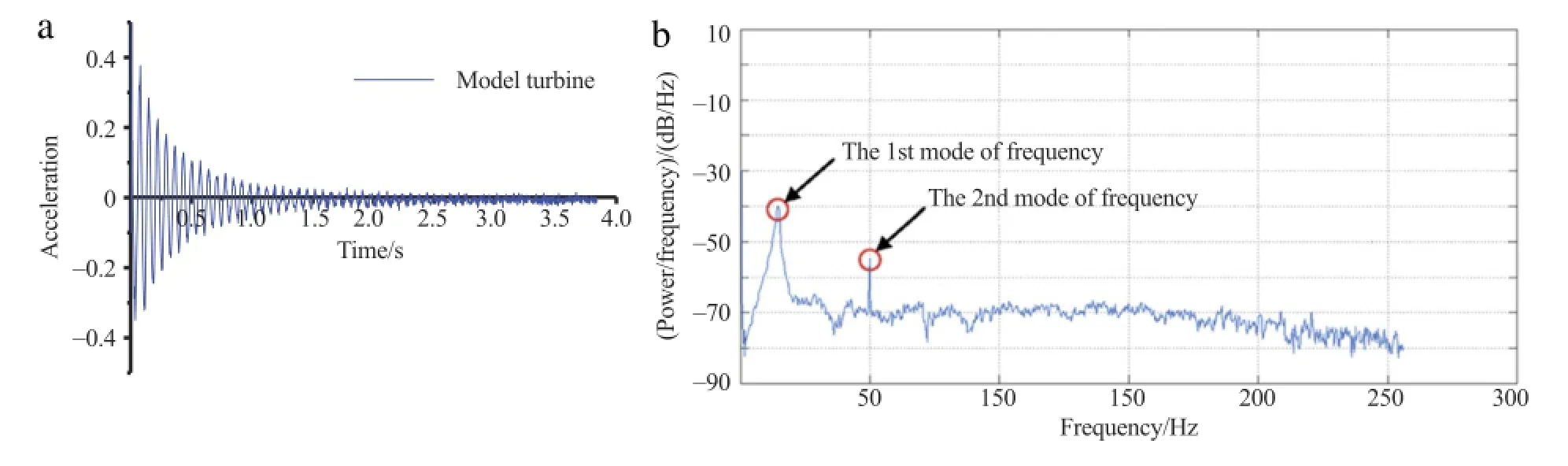
Fig.6.(a)Acceleration records from free vibration test.(b)Frequency response from Welch’s method.

Fig.7.(a)Change of structure’s natural frequency.(b)Change of sand’s shear modulus under different strain level[18].

Table 3Detailed scheme of the test programme.
Taking into account the medium dense state sand used in the test,with the decrease of soil void ratio under cyclic loading,the sand will get densified,and will lead to an increase in the foundation stiffness,which ultimately contribute to the increase of structure’s natural frequency.While the decrease of the system’s natural frequency during the late period could be attributed to the sand particles’migration and loss mechanism,further details on this aspectcan be found in Ref.[13].Itis interesting to note thatthe results from the resonant column test given in Fig.7(b)[18]could be used to explain the modeltestresults.Itcan be clearly seen from Fig.7(b),when the soil strain level is low(i.e.,γc=1.6×10⁻⁴),change of its shear modulus with respect to the number of cycles is negligible.In contrast,when the soil strain reaches a high level(i.e.,γc=6×10⁻⁴),the soil’s shear modulus grows with the increase of cycles.This phenomenon matches well with the model test results as observed in Fig.7(a):high values of soil strain level(i.e.,P/GD2)will lead to high increment of natural frequency.
Conclusions In this paper,a simple,economic,and innovative device has been adopted to apply cyclic loads.The natural frequency of the model turbine supported on pile in sand,is found to increase with the load cycles,after reaching a certain number of cycles,it tends to stabilize and then decrease with more load cycles. Higher level of the amplitude of cyclic loading will lead to higher amplitude of natural frequency’s increment.Increase of the model structure’s natural frequency is attributed to the densification of the surrounding soil under cyclic loading,while the soil particles’migration and loss mechanism will lead to the decrease of the system’s natural frequency.Therefore,the natural frequency of OWT is recommended to put close to the upper limit of 1P band for the strain stiffen sand field.
Acknowledgment This work was supported by the National Natural Science Foundation of China(51109184,51209183 and 51325901).
[1]D.Lombardi,S.Bhattacharya,D.M.Wood,Dynamic soil-structure interaction of monopile supported wind turbines in cohesive soil,Soil Dyn.Earthq.Eng. 49(2013)165-180.
[2]W.H.Hu,S.Thöns,S.Said,W.Rucker,Resonance phenomenon in a wind turbine system under operational conditions,in:Proceedings of the 9th International Conference on Structural Dynamics,EURODYN,Porto,Portugal,2014.
[3]L.Z.Wang,L.Q.Yu,Z.Guo,Z.Y.Wang,Seepage induced soil failure and its mitigation during suction Caisson installation in silt,J.Offshore Mech.Arctic Eng.136(2014)1-11.
[4]P.Cuellar,M.Baebler,W.Rucker,Ratcheting convective cells of sand grains around offshore piles under cyclic lateral loads,Granular Matter.11(2009)379-390.
[5]K.T.Chang,D.S.Jeng,etal.,Soilresponse around Donghaioffshore wind turbine foundation,in:Proceedings of the ICE,Geotechnical Engineering,vol.167,2014,pp.20-31(in Chinese).
[6]Det Norske Veritas,Offshore Standard:Design of Offshore Wind Turbine Structures.DNV-OS-J101,Hovek,Norway,2007.
[7]S.Thöns,M.H.Faber,W.Rücker,Fatigue and serviceability limit state model basis for assessment of offshore wind energy converters,J.Offshore Mech. Arctic Eng.134(2012)031905.
[8]S.Thöns,M.H.Faber,W.Rücker,Ultimate limit state model basis for assessment of offshore wind energy converters,J.Offshore Mech.Arctic Eng. 134(2012)031904.
[9]A.Staino,B.Basu,Dynamic and control of vibrations in wind turbines with variable rotor speed,Eng.Struct.56(2013)58-67.
[10]W.Y.Liu,The vibration analysis of wind turbine blade-cabin-tower coupling system,Eng.Struct.56(2013)954-957.
[11]M.B.Zaaijer,Foundation modeling to assess dynamic behavior of offshore wind turbines,Appl.Ocean Res.28(2006)45-57.
[12]M.Achmus,Y.S.Kuo,K.A.Rahaman,Behavior of monopile foundations under cyclic lateral load,Comput.Geotech.36(2009)725-735.
[13]C.Leblanc,B.W.Byrne,G.T.Houlsby,Response ofstiff piles in sand to long term cyclic loading,Geotechnique 60(2010)79-90.
[14]S.Bhattacharya,D.Lombardi,D.M.Wood,Similitude relationships for physical modelling of monopile-supported offshore wind turbines,Int.J.Phys. Modelling Geotech.11(2011)28-68.
[15]S.Bhattacharya,N.Nikitas,J.Garnsey,N.A.Alexander,J.Cox,D.Lombardi,D. Muir Wood,D.F.T.Nash,Observed dynamic soil-structure interaction in scale testing of offshore wind turbine foundations,Soil Dyn.Earthq.Eng.54(2013)47-60.
[16]S.Bhattacharya,S.Adhikari,Experimental validation of soil-structure interaction of offshore wind turbines,Soil Dyn.Earthq.Eng.31(2011)805-816.
[17]S.Bhattacharya,A.Murali Krishna,D.Lombardi,A.Crewe,N.Alexander,Economic MEMS based 3-axis water proof accelerometer for dynamic geoengineering applications,Soil Dyn.Earthq.Eng.36(2012)111-118.
[18]V.P.Drnevich,J.R.Hall,F.E.Richard,Effects of amplitude of vibration on the shear modulus ofsand,in:Proc.,Int.Symp.on Wave Propagation and Dynamic Properties of Earth Mat.,Albuquerque,N.M.,1967,pp.189-199.
[19]P.D.Welch,The Use of Fast Fourier Transform for the Estimation of Power Spectra:A Method Based on Time Averaging Over Short,Modified Periodograms,1967.
∗Corresponding author.
E-mail address:wlzzju@163.com(L.-Z.Wang).
*This article belongs to the Solid Mechanics
 Theoretical & Applied Mechanics Letters2015年2期
- Theoretical & Applied Mechanics Letters的其它文章
- Failure mechanisms of a spudcan penetrating next to an existing footprint
- Difficulties and measures of driving super long piles in Bohai Gulf
- Assessment of pipeline stability in the Gulf of Mexico during hurricanes using dynamic analysis
- Coupling model for waves propagating over a porous seabed
- Elasto-plasticity and pore-pressure coupled analysis on the pullout behaviors of a plate anchor
- Experimental study on the stability of plate anchors in clay under cyclic loading