
Dynamic Model Identification for Ultrasonic Motor Frequency-SPeed Control
2015-11-24 02:39ShiJingzhuo史敬灼SongLe宋乐
Shi Jingzhuo(史敬灼)*'Song Le(宋乐)
College of Electrical Engineering'Henan University Science and Technology'Luoyang 471023'P.R.China
Dynamic Model Identification for Ultrasonic Motor Frequency-SPeed Control
Shi Jingzhuo(史敬灼)*'Song Le(宋乐)
College of Electrical Engineering'Henan University Science and Technology'Luoyang 471023'P.R.China
The mathematical model of ultrasonic motor(USM)is the foundation of the motor high performance control.Considering the motor speed control requirements'the USM control model identification is established with frequency as the independent variable.The frequency-speed control model of USM system is developed'thus laying foundation for the motor high performance control.The least square method and the extended least square method are used to identify the model.Ey comparing the results of the identification and measurement'and fitting the time-varying parameters of the model'one can show that the model obtained by using the extended least square method is reasonable and possesses high accuracy.Einally'the frequency-speed control model of USM contains the nonlinear information.
ultrasonic motor;speed control;extended least square method
0 Introduction
Since ultrasonic motor(USM)has the performance and characteristics different from those of the traditional electromagnetic motors'it is widely used not only in the domestic electronics' micro-robots'aerospace'and so on'but also has broad application prospects in many control fields of motion control[1].With further research on USM'the relatively lagging motion control method of USM becomes the main factor to restrict its widely used.
The mathematical model of USM is the basis for analyzing and mastering the nonlinearity in its operation.And it is a necessary premise for studying and designing the control strategies'e.g. adaptive'which makes the modeling method for USM control become the foundation of motion control study.The model obtained from theoretical modeling or numerical modeling is too complex for real-time applications[2-3]because the operation of USM contains a series of processes with nonlinearity and large dispersibility such as piezoelectric energy conversion'friction energy transfer'etc.Therefore'the study of USM control model and the corresponding modeling method can be suitable for the main operational characteristics and USM control'which has been one of the research directions at present[4-6].
Considering the requirement of the speed control of USM'which set the driving frequency as the independent variable'the system identification method is used to establish the frequencyspeed control model of USM system.It is benefit to the high performance research of speed control.In the paper'including the design of experiment'the identification modeling process and method are discussed.And it can be a reference for the modeling research of USM and traditional electromagnetic motor.
1 Design of ExPeriment for Data Test
System identification is a kind of experimen-tal modeling method'which measures and evaluates the input and the output data of the identified object to get the approximate mathematical model.The output signal is the response of the input signal through the identified object.If the input signal is appropriately selected and designed'we can get a desirable mathematical model of the object by a relatively simple identification method[7].Studies show that the white noise with broad spectrum and constant amplitude is an ideal input signal for model identification.However'it is difficult to be obtained.Therefore'pseudo-random signal with similar statistical characteristics is usually used as input signal in actual model identification.Among these signals'the longest linear shift register sequence(M sequence)is widely used for it has simple form'excellent statistical properties and is easy to be obtained.
The M sequence must satisfy certain conditions when used as the input signal for motor model identification.In order to not only make the effective frequency band of M sequence cover the whole expected identification band and possess the statistical characteristics similar to white noise in the frequency range'but also ensure the system features of the identified motors can be excited sufficiently and continuously'thus'the length Npof M sequence'the sampling timeΔt and other parameters should be designed to satisfy the following empirical formulas
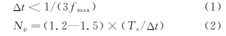
where fmaxand Tsare the maximum operating frequency and the dynamic transition time of the motor system to be identified'respectively.
Two-phase traveling wave USM USR60 is to be identified.In order to get its frequency-speed model for control'the input and the output signals are driving frequency and speed'respectively.The tested frequency-speed step response curves of different amplitudes show that the transition time Ts<80 ms.Hence'considering the control performance and actual condition of the system'the maximum operating frequency fmaxshould be set to 500 Hz.According to the empirical formula above'the sample timeΔt<1/(3fmax)=0.67 ms.Therefore'we set the sample timeΔt as 0.5 ms.The value of Npshould not be less than 1.2×(Ts/Δt)=192.Therefore'we set the M sequence length Npas 255'i.e.the 8 bit M sequence with the period of 127.5 ms.The amplitude of M sequence signal should ensure the variation range of motor speed relatively large to improve the signal-to-noise ratio(SNR)of the measured signal as high as possible.However' the mechanism of USM limits the adjustment of its frequency of the driving voltage in a small scope.The motor will stall once it goes beyond the limitation.Considering the operating characteristics of the USM USR60'the amplitude of M sequence signal is set as 250 Hz.Eig.1 shows the M sequence signal used in the experiments.
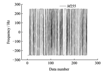
Eig.1 M sequence used in the experiments
The controllable variables of two-phase traveling wave ultrasonic motors are the frequency of the driving voltage'the amplitude'the phase difference'etc[8].The speed of motor will be changed if any of the three factors is altered.In order to ensure the operational state of the motor close to the ideal situation'the phase difference is not usually adjusted to control the speed but fixed at±90°instead.Therefore'the motor speed is only related to frequency and amplitude.The modeling purpose of the paper is to achieve the closed-loop control of motor speed by adjusting the frequency.In order to design the speed closed-loop controller'the frequency-speed dynamic model of the motor is necessary'and the impact of the voltage amplitude to speed shouldbe taken into account as well.Therefore'based on the expected working state of the closed-loop control system'the experiments of obtaining input and output data are designed as:Set the amplitude of the driving voltage as a fixed value'and the frequency of the driving voltage as the input signal'then the response data of the speed of motor.Since USM can only operate within a small frequency range'we select different frequency basic values superimposing M sequence signal as the input frequency signal in the experiments to ensure the normal operation of the motor.Moreover'the basic values of the frequency should be selected to make the measured values of motor speed cover the entire range of usable speed.The above experiment is conducted'then'the amplitude of the driving voltage should be changed to repeat the process of experiments as above-mentioned.Einally'based on these experimental data'the dynamic frequency-speed model can be achieved by identification considering the influence of amplitude of the voltage.
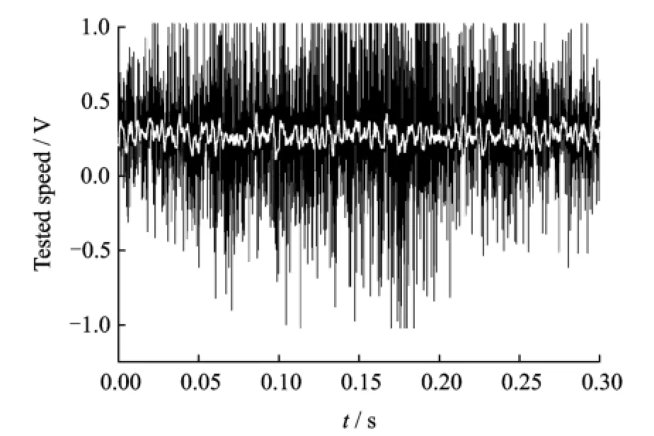
Eig.2 Tested speed response data
In the experiments'a DC tachogenerator is rigidly coaxially connected with the measured motor.And the output voltage of the tachogenerator are sampled as the tested data for the output speed of motor.When the M sequence is added to the input signal'it is hard to obtain the actual speed signal'for the output signal of speed contains lots of noises.To ensure the accuracy of the data measured'the record of data should keep away from this section of the signal.Hence'the experiment is designed to start collecting test data from the fiftieth M sequence cycle.The recording time is 0.4 s'slightly longer than three M sequence periods.The two test data of these periods is used for identification calculation'and the other is used for model validation.
2 ExPerimental Analysis of Testing Data
When the peak-peak value of the driving voltage of USM reaches 300 V'30 groups of input and output data at different speeds which cover the whole usable range of speed are measured. Eor each speed'two groups of input and output data are measured continuously to avoid the impact of abrupt external interference.The analysis of 30 groups of data indicates that the two groups of data tested at the same speed have good consistency'namely no obvious difference.The tested basic values of input frequency f and the corresponding motor speed values are shown in Table 1.As mentioned above'the measured values of the experiments are the response data of the output speed corresponding to different frequency basic values superimposing M sequence signal. Taking the first group tested data in Table 1 for example'the basic value is 41.657 k Hz'and the corresponding frequency jump range becomes 41.407—41.907 k Hz when M sequence signal is superimposed(Eig.1).

Table 1Partial test data distribution
The rated speed of the measured motor is 100 r/min.Since the speed of motor is low'theamplitude of the output voltage of tachogenerator is low as well(valid data<0.7 V).Thus'the noise is obvious in the actual measurement data as shown in black line in Eig.2.The calculation indicates that SNR of the measured speeds are all less than 15 dE'and with the decrease of the speed'SNR will decrease even to negative'which is unfavorable for any identification algorithm.In order to reduce the effect of noise'the measured speeds should be pretreated with the methods like low-pass filtering.Considering the reqirement of control response that bandwidth should not be larger than 500 Hz'the low-pass filtering with the cut-off frequency of 1 000 Hz can be conducted on the measured speed data.In this way'the measured speed data is obtained by the identification calculation as the white line in Eig.2.It can be seen from the white line that the selected amplitude of M sequence can change the speed of motor significantly.
3 Model Identification for USM Frequency-SPeed Control
The least square method is an identification algorithm widely used in control field to get the minimal optimal estimation results for the criterion function of residual sum of squares[9].Then' the frequency-speed control model of the ultrasonic motor USR60 is identified by using the method.To make it universal'the frequencyspeed random variance model of USM is set as

where

where y(k)is the output data'u(k)the input data'andε(k)the white noise.a1'…'ana'b1'…' bnbare the model parameters to be identified which are noted as a=a1'…'ana;b=b1'…'bnb.
Considering both of the requirements of the precise of identification and the feasibility of the model obtained to apply in the actual system'the order of model can be selected as four or five initially.According to the algorithm above'under the two kinds of model order of the measured data'we use Matlab to caculate identification.Einally'the model with the same order and different numbers of zero points are obtained.The most appropriate model structure is determined by comparing the model verification results.In order to verify the validity of the model obtained by identification'the cursive calculation is conducted by using the model established on the basis of the input data'and the output of model is achieved as

Eig.3 shows the comparison between the model outputsˆy(k)by calculated and the measured values of a set of data.In Eig.3'arx 440 represents the least square method'and the order of model is na=4'nb=4;wf1 represents the test data of modeling.It should be noted that the length of actual time of the data is 0.4 s.In order to make the graph clear'only some typical data are given.To illustrate the convergence process of the recursive calculation of Eq.(6)'the data given in Eig.3 are starting at the time of 0.
It can be seen from Eig.3 that the output of model is close to the measured data while there is still obvious deviation between them.The main reason is that the least square method requires the noiseε(k)in the system to be white noise.
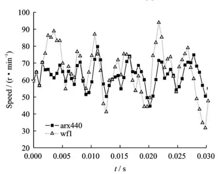
Eig.3 Model verification using least square method
However'the measured noise of the actual motor system is always some kind of colored noise e(k)'which affects the approximation de-gree of model parameter identification.According to the representation theorem'the colored noise e(k)in the actual system can be expressed by the white noiseε(k)

where

Obviously'the model with noise should be taken into account to get a better identification effect in the identification process.Extended least square method is a kind of method that can identify the parameters of model and the parameters of the model with noise simultaneously.Considering the noise'the stochastic difference of the frequency-speed model of USM can be expressed as

where c1'…'cncare the parameters which should be identified.
The model parameters in the conditions of same model order and different numbers of zeros are obtained by conducting identification calculation through programming with extended least square method.The output of modelˆy(k)is obtained by recursive calculation based on the output data and the structure and parameters of the model.One set of the calculated data is shown in Eig.4'where armax4430 represents the least square method'and the order of model is na=4' nb=4 and nc=3.It can be seen that the identification effect when using the extended least square method is better than using the least square method.And the consistency between the output of model and the measured verification data is improved obviously.
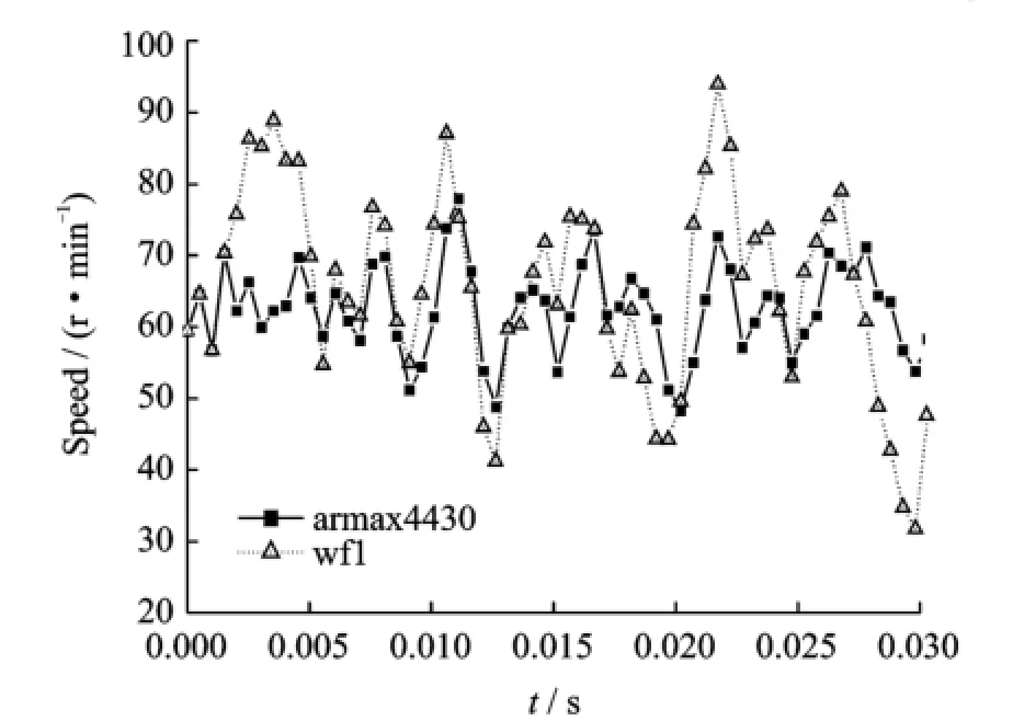
Eig.4 Model verification using extended least square method
Eigs.3'4 and identification calculations of many models show that when the order of model is five'the identification effect is better than that of four order models.With the same order of model'the more the zeros'the better the effect. Therefore'the structure of motor′s model should be set as five orders and the number of zeros is five'that is

The model of motor is set as Eq.(10).Eor the experimental data measured under frequencies and driving voltages'the parameters of a and b are obtained by using the extended least square method to identify the frequency-speed method. The values of some typical parameters are shown in Tables 2'3.The variance between the output data of the identified model and the measured data are shown in the second column of Table 4.
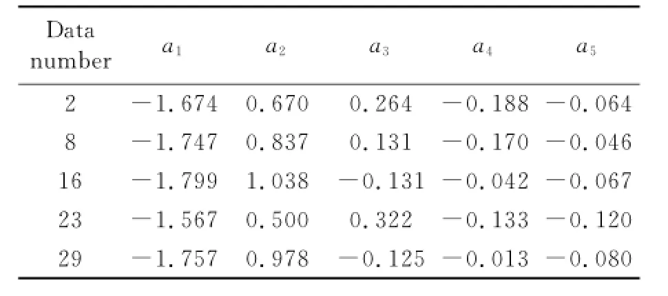
Table 2 Identification model Parameter a using extended least square method
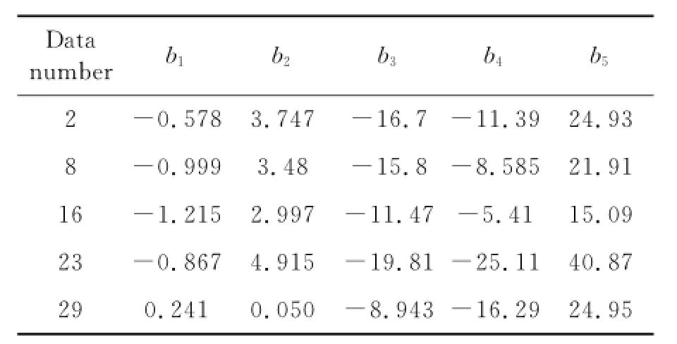
Table 3 Identification model Parameter b using extended least square method
A set of the verified results under different amplitudes of the driving voltage are shown in Eigs.5'6'where armax5530 represents the extended least square method'and the order ofmodel is na=5'nb=5 and nc=3;wefe represents the test data of fitting.It shows that the model obtained by identification is reasonable and has high precision'and it can meet the requirement of control.
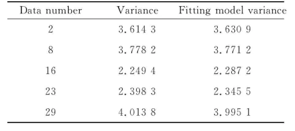
Table 4 Variance between identification model outPut and measured data
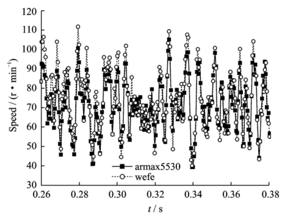
Eig.5 Model verification using extended least square method(Uref=300 V)

Eig.6 Model verification using extended least square method(Uref=250 V)
4 Model ExPression with Time-Varying Parameters for Frequency-SPeed Control
Ey the analysis of Tables 2'3'we can see that the model parameters have obvious time-varying characteristic'and it reflects the strong nonlinearity of the USM.In order to make the model full reflect the time-varying nonlinearity of the motor'the time-varying characteristic of the parameters should be expressed in the motor model.Due to the fact that the motor will show different characteristics under different frequencies of the input'the time-varying nonlinearity can be characterized by the change of model parameters with the change of frequency.Eurthermore'the output of the speed controller is the given value of frequency in the actual control process of the USM system.The given value of frequency can be seen as actual value.If the dynamic process of frequency regulation is ignored(This response process is fast enough compared with the control response process).Hence'the frequency value is the known quantity in the real-time control process'and the control model of motor is computable with the frequency as the independent variable.Thus'the frequency f can be used as independent variable to fit parameters of a and b' and they are expressed as a(f)and b(f)'respectively.Eased on the change rules of model parameters'polynomial functions that only contain multiply and add operation are selected to fit the parameters.Therefore'it is convenient to use control chips such as DSP to calculate online.
The fitting calculation shows that under different amplitudes of voltage'all the polynomial functions with the order lower than three can achieve good fitting of the parameters a1—a5and b1—b5.The form of fitting functions is shown as Eq.(11).
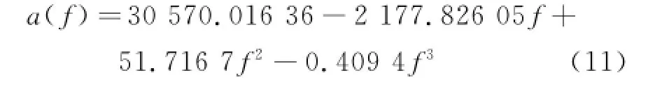
After the above identification and the fitting calculation of the time-varying of parameters'the final frequency-speed control model of the USM system is obtained as follows

Eig.7 is a set of model verification resultsobtained by using the fitted model parameters' which are consistent with the calculated results of model parameters obtained from the identification.The third column of Table 4 shows the variances between the output data of the corresponding identification model and the experimental data.

Eig.7 Model verification using fitting parameters
To further verify the validity of the obtained model'the pole assignment speed controller of USM is designed by using the fitting model of Eq.(12)'and the frequency of driving voltage is set as the control variable.Then'the closed-loop speed control of the experimented motor USR60 is conducted.The model parameters are changing with the change of the driving frequency of the motor.Therefore'the parameters of the speed controller are changing online to ensure a better adaptibility.Eig.8 shows the tested step response of speed when the motor is in an unloaded state. It can be seen that the step response has small overshoot and quick response'and the consistency of the speed response process of the motor is admirable at different speeds.
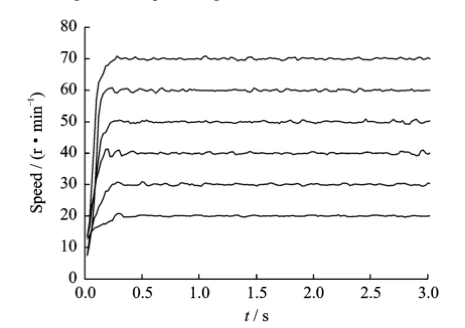
Eig.8 Measured step response of speed
5 Conclusions
The speed data are designed to measure at specific situation of the two-phase traveling wave ultrasonic motor.The frequency-speed control model of USM system is identified by the least squares algorithm'and the control model obtained contains the nonlinear information.
Result shows that the model is an approximate description of the actual system.And the obtained model is suitable for the application of frequency-speed control.In other words'it is a better model fitting the dynamic characteristics of USM while considering the control requirements and feasibility.
To establish the motor of USM by identification'we should select appropriate input signal to fully motivate the characteristics of the motor that we concern'and the M sequence is a good choice.
The design of the experiments and the selection of input signal parameters should both ensure the identification demands and improve SNR of the test data.Meanwhile'the test data should be pretreated by low-pass filtering for the identification accuracy.
The colored noise is the mainly measurement noise in the motor system.Extended least square method has better tolerance to the colored noise and the identification effect is better than the least square method.
The model parameters are the important parts of the motor model.The time-varying expression form of the parameters is an effective mean to express the nonlinear dynamic characteristics of the motor system.
Acknowledgement
This work was supported by the National Natural Science Eoundation of China(No.U1304501).
[1] Zhao Chunsheng.Ultrasonic motor technology and application[M].Eeijing:Science Press'2007.(in Chinese)
[2] Wang Xinjian'Jin Long'Yao Eo'et al.System identification model of traveling wave ultrasonic motors based on nonparametric estimation method[J]. Chinese Journal of Electrical Engineering'2008'28(18):83-89.(in Chinese)
[3] Senjyu T'Nakamura M'Urasaki N'et al.Mathematical model of ultrasonic motors for speed control[C]∥21st Annual IEEE'Applied Power Electronics Conference and Exposition'2006(APEC′06).Dallas'TX'United States:IEEE'2006.
[4] Pirrotta Simone'Sinatra Rosario'Meschini Alberto. A novel simulation model for ring type ultrasonic motor[J].Meccanica'2007'42(2):127-139.
[5] Juang P'Tsai C.Equivalent circuit modeling of an asymmetric disc-type ultrasonic motor[J].IEEE Transactions on Instrumentation and Measurement' 2009'58(7):2351-2357.
[6] Chen T C'Yu C Hn'Tsai M C.A new driver based on dual-mode frequency and phase control for traveling-wave type ultrasonic motor[J].Energy Conversion and Management'2008'49(10):2767-2775.
[7] Zhang Jiantao'Zhang Tiemin'Liang Li.Nonlinear modeling and generalized predictive control of ultrasonic motor[J].Electric Machines and Control' 2011'15(6):50-56.
[8] Senjyu T'Kashiwagi T'Uezato K.Position control of ultrasonic motors using MRAC and dead-zone compensation with fuzzy inference[J].IEEE Transactions on Power Electronics'2002'17(2):265-272.
[9] Chen Xingmin.Recursive identification for MIMO Hammerstein systems[J].IEEE Transactions on Automatic Control'2010(4):895-902.
(Executive editor:Xu Chengting)
TM383 Document code:A Article ID:1005-1120(2015)02-0218-08
*CorresPonding author:Shi Jingzhuo'Professor'E-mail:sjznew@163.com.
How to cite this article:Shi Jingzhuo'Song Le.Dynamic model identification for ultrasonic motor frequency-speed control[J].Trans.Nanjing U.Aero.Astro.'2015'32(2):218-225.
http://dx.doi.org/10.16356/j.1005-1120.2015.02.218
(Received 5 January 2015;revised 28 January 2015;accepted 12 Eebruary 2015)
 Transactions of Nanjing University of Aeronautics and Astronautics2015年2期
- Transactions of Nanjing University of Aeronautics and Astronautics的其它文章
- StePPing Control Method of Linear DisPlacement Mechanism Driven by TRUM Based on PSoC
- Design and ExPeriment of Vertical Motion Dual-stage with Piezo-actuated NanoPositioning Stage
- Large Thrust Trans-scale Precision Positioning Stage Based on Inertial Stick-SliP Driving
- Intelligent Control Algorithm of PTZ System Driven by Two-DOF Ultrasonic Motor
- Dynamic Loads and Wake Prediction for Large Wind Turbines Based on Free Wake Method
- Numerical Investigation on Drag Reduction Effect by Mass Injection from Porous Boundary Wall