
Hydrodynamics and modeling of a ventilated supercavitating body in transition phase*
2015-11-25 11:31KIMSeonHongKIMNakwan
水动力学研究与进展 B辑 2015年5期
KIM Seon-Hong, KIM Nakwan
Department of Naval Architecture and Ocean Engineering, Seoul National University Seoul, Republic of Korea,E-mail: rlatjsql@snu.ac.kr
Hydrodynamics and modeling of a ventilated supercavitating body in transition phase*
KIM Seon-Hong, KIM Nakwan
Department of Naval Architecture and Ocean Engineering, Seoul National University Seoul, Republic of Korea,E-mail: rlatjsql@snu.ac.kr
2015,27(5):763-772
Compared to other underwater vehicles, supercavitating vehicles can attain a high speed because they eliminate drag by creating a large cavity, thus establishing the so-called “supercavitating condition.” Such a cavity is difficult to develop under normal conditions, hence, ventilation is used to attain the supercavitating condition in the initial phase of flight. In this paper, we focus on the hydrodynamic characteristics of a ventilated supercavitating vehicle. First, dynamic modeling of the supercavitating vehicle is performed to calculate the hydrodynamic force/moment acting on the vehicle for a given size of cavity. We then define the relationship between the ventilation rate and the cavitation number based on an air entrainment model of the ventilated cavity. Numerical simulations were performed to analyze the physical feasibility and characteristics of the modeling. The results show that the cavity length/radius increases with the ventilation rate, proving that ventilation can be used to attain the supercavitating condition.
entilated supercavity, hydrodynamical modeling, supercavitating body, transition phase, cavity closure mode, dynamics modeling
Introduction
Supercavitating technology is applied to underwater vehicles as a means of overcoming the limit on their speed resulting from drag. It was developed based on the concept that the wetted surface of an underwater vehicle can be eliminated by surrounding the vehicle with a bubble of gas. The bubble of gas is called a “cavity” while a supercavity is that state in which the cavity is large enough to envelop the entire body of the vehicle. The cavity can occur naturally as in the case of an object moving underwater at high speed, such as in the case of a propeller, or it can be created artificially by blowing gas into the cavity. The former is called “natural cavity” and the latter is a“ventilated cavity.” The performance of the vehicle depends on how quickly it can reach the supercavitating condition and, by extension, how quickly it can make a cavity large enough to envelop the entire vehicle body. The ideal condition for developing supercavitation is high speed and shallow depth. Generally, however, the condition is less than ideal in the initial phase of flight. Therefore, ventilation provides an effective means of leading to the creation of a supercavity, especially under such non-ideal conditions.
The dynamics and characteristics of a supercavitating vehicle have been studied by many researchers,but their efforts have not addressed the modeling of a supercavitating system in the transition phase, and have instead been limited to a portion such as longitudinal dynamics. Dzielski and Kurdila researched the modeling and control problem in the early development phase[1]. The longitudinal dynamics and control problem were studied by[2-4].
Basic research for the formation of the cavity length and shape was undertaken in the mid to late 1990s[5-7]. Varghese et al.[8]studied the characteristics of a supercavitating body in the partially cavitating condition. Research related to gas-leakage from a ventilated cavity in a twin-vortex regime was studied by Campbell and Hilborne[9]while Spurk[10]addressed the same in a toroidal vortex. Semenenko described this in detail with respect to the physical characteristics and modeling of a ventilated cavity[11]. Kinzel suggested the modeling of a ventilated cavity considering all types of cavity closure modes[12]. Recently, Zouet al.[13]studied the gas-leakage rate of an unsteady ventilated supercavity and established a gas leakage formula.
In this study, a six degree-of-freedom (DOF)equation of motion for a supercavitating vehicle system is constructed, with the goal of modeling a ventilated supercavity considering the cavity closure types. A supercavitating vehicle system was divided into the cavitator, fins, and vehicle body while the forces and moments acting on each part were determined for a range of cavity sizes. The modeling of each part was based on previous research, and we integrated them to define the dynamics of the supercavitating system. In the modeling part, we define all the terms included in the 6-DOF equation of motion in Section 1.1, while the calculation of the terms is explained in Sections 1.2 to 1.7. After the mathematical model is constructed, we perform a numerical simulation of a ventilated cavity and open loop system in Section 2. In the simulation results, the results of the numerical simulation are presented such that we can identify whether the modeling is physically reasonable. In Section 3,the conclusions and discussions of the study are presented.

Fig.1 Supercavitating vehicle
1. Modeling of supercavitating vehicle
1.1 6-DOF equation of motion
The cavitator is located at the front of the vehicle,and a disk and four fins are located aft in the shape of a cross(+), as shown in Fig.1. We selected two coordinate systems, namely, an earth-fixed coordinate system OE-XEYEZEand a body-fixed coordinate systemOB-XBYBZB, as shown in Fig.1. The origin of the earth-fixed coordinate system was at sea level (zero)while the origin of the body-fixed coordinate system was located at the center of gravity.
The forces and moments acting on the vehicle are generated by the four fins, the cavitator, gravity, thruster, wetted area of the body, and planing. The nonlinear equations of the supercavitating vehicle can be derived by using the linear momentum and angular momentum equations.
Here,(u,v,w)are the linear velocities during the surge, sway, and heave motions, and(p,q,r)are the angular velocities during the roll, pitch, and yaw motions. In this paper, we assume that the thrust force is acting only in theXB-direction with magnitudeT.

Fig.2 Axisymmetric cavity and cavity sections
1.2 Cavity model
The cavity is the major component of a supercavitating system. The behavior of the cavity bubble around the vehicle affects the fins and body immersion. The cavitator continuously creates a cavity while the vehicle is moving. The cavity center and axis are equal to the trajectory of the cavitator, provided there is no gravity effect and the cavitator angle of attack is zero, in other words, when the cavity is axisymmetric. The plane that is perpendicular to the trajectory of the cavitator is called the “cavity section” and the cavity contour is obtained by integrating all of the cavity sections along the trajectory of the cavitator. The cavity changes with time, independently of the vehicle dynamics. Each cavity section first expands until it reaches its maximum radius and then starts to contract and disappear (Fig.2). The semi-empirical formula of Ref.[14]also represents the cavity radius of each cavity section:

The cavity shape and cavity axis are calculated because the immersion of the vehicle, which plays animportant role in the hydrostatic/dynamic forces, is determined by the position of the cavity relative to the vehicle. Figure 3 shows the delayed cavity section. The vehicle immersion can be calculated from the location of the cavity center at the fin,Xcavity, and the cavity radius. LetXcavitator(t)be the present cavitator position andτbe the time required for the cavity to reach the position of the fins. The position of the cavitator at the time t-τ in the earth-fixed frame can be written as follows
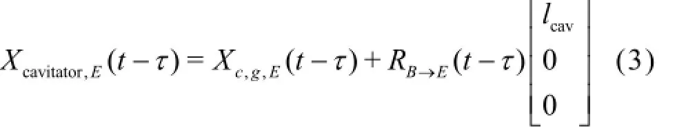
Xcavitator,Eand Xc,g,Eare the cavitator location and center of gravity in the inertial frame,lcavis the distance between the center of gravity and the cavitator,andRB→Eis the rotation matrix from the body frame to the earth-fixed frame.

Fig.3 Delayed cavity section

Fig.4 Mass balance in supercavity
1.3 Ventilated cavity model
The main problem presented by the ventilated cavity is the calculation of the magnitude of the gas supply required to maintain a given cavitation number(i.e., a given cavity size). Therefore, the relationship between the gas supply for ventilation and the cavitation number should first be defined. Mass balance in supercavity is shown in Fig.4. The mass balance equation for a ventilated supercavity can be written as follows

Here,m˙inand m˙outare the mass flow rates into the cavity and escaping from the cavity, respectively.
By assuming that the flow inside a cavity is isotropic, incompressible, and adiabatic, Eq.(4) can be transformed to Eq.(5).

Here,pcis the pressure inside the cavity,andare the volumetric gas flow rates into and out of the cavity, respectively. Becauseis equal toin the steady state, the cavitation number(σ)according to the gas leakage rate)is an important issue for determining a ventilated cavity.
There are three types of cavity closure modes. The characteristics of the gas leakage depend on its cavity closure mode.
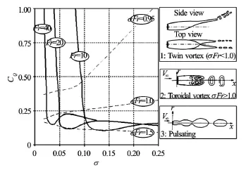
Fig.5 Sample CQ-σcurve with corresponding cavity types,figure taken from [12]
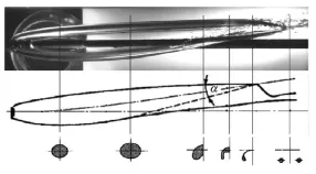
Fig.6 Image of twin vortex cavity and scheme of deformation of cavity, figure taken from [15]
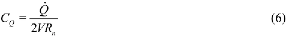
Diagrams of the cavity types are shown in Fig.5. CQis the ventilation coefficient, defined by Eq.(6).
Semenenko[11]found that the cavity closure modes can be divided into three types: twin-vortex, to-roidal vortex, and pulsating. Twin-vortex closing cavities are rather large, stable, transparent cavities. The effects of gravity are significant for this type of closure mode (Fig.6).
The twin-vortex type has been the object of most studies, both theoretical and experimental.
In this paper, the twin-vortex mode model presented by Campbell and Hilborne[9]is used. This model is based on the correlation between the circulation around the cavity centerline and the buoyant loads on the cavity. Zou proposed a slightly modified form of the Campbell and Hilborne model, as follows[13]

Here,FrNis the Froude number scaled by the cavitation diameter, while VVTis the velocity of the air traveling out of the cavity.Aandk are empirical parameters that are approximately 2.0 and 1.0, respectively.
There have been very few studies of toroidal vortex cavity closing. It is known that this type of cavity is non-stationary, multi-parametric, and unsteady with gas being periodically rejected at the tail of the cavity,as shown in Fig.7.
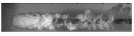
Fig.7 Toroidal vortex cavity closure, figure taken from [15]
Spurk[10]recently suggested the importance of the mechanisms occurring upstream of these toroidal vortices, and that the air being transported along the interfacial shear layers to the end of the cavity consist of air that eventually fills the toroidal cavities. The theory is in good agreement with measured results under high FrNconditions and for reentrant cavities with minimal buoyancy.
Spurk’s model is given as

where kQis an empirically determined constant and approximately 0.02 in this study.
It was noted that the determinant variables of the cavity closure modes are the cavitation number and Froude number. A twin vortex is formed when the σFrNvalue is less than 1, while a toroidal vortex is formed when the value is greater than 1. The transition between the two modes occurs when the value is around 1[9]. However, recent experiments have shown that the transition occurs when the value is 6 not 1[15]. The transition regime is still an area of development,including the hysteresis phenomenon. Kinzel et al.[12]proposed a cavity closure model covering the toroidal,transition phase, and twin vortexes, but the proposed model cannot exactly represent gas leakage in the transition phase. The model is shown in Fig.8.
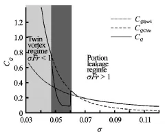
Fig.8 Kinzel’s gas leakage model
The third type of cavity closure is the pulsating cavity. This type of cavity closure is unstable. Generally, a cavity loses its stability when the gas supply rate is very high. Paryshev developed the linear stability theory for a ventilated cavity whereby the stability is determined by dynamics parameterβ, which is a dimensionless parameter expressed as follows[16]

where σvis the natural cavitation number. The cavity is stable when 1≤β<βcri=2.645and unstable when β>2.645. The large value ofβis equal to small values ofσand implies that the gas supply into the cavity is much greater than the cavity can contain. The self-induced vibration in pulsating cavity mode is the cause of the stability loss.
1.4 Cavitator model
The cavitator is a fundamental part of the vehicle. It creates a cavity bubble around the body and generates forces and moments by changing the deflection angle to control the vehicle. The cavitator shape was assumed to be a disk that rotates only about the yaxis. The following relationships have been employed to estimate the drag and lift coefficients acting on the disk cavitator in the flow axis[17]:
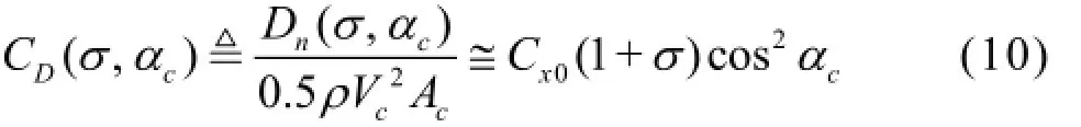
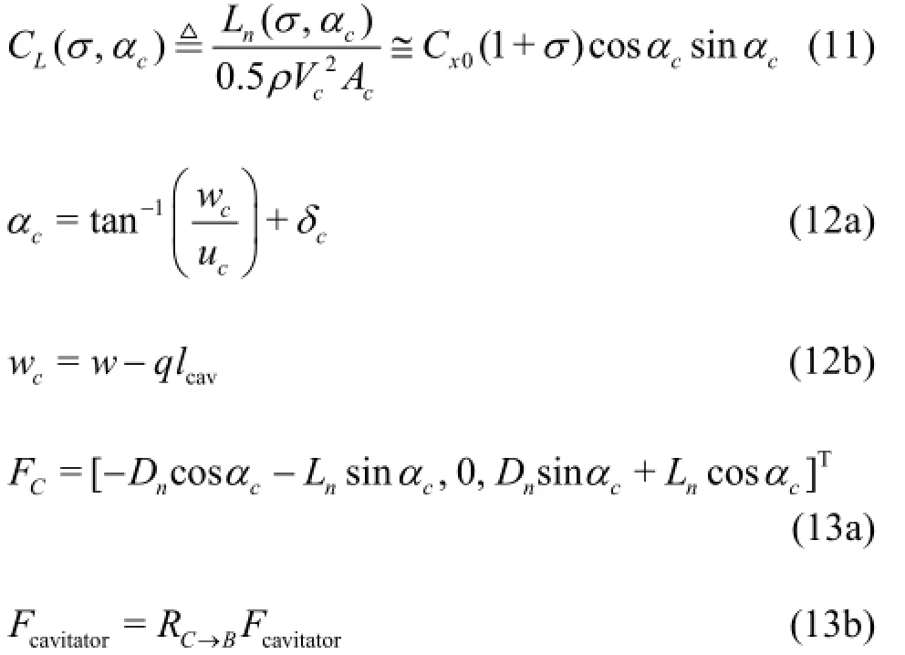
where CDand CLare the drag and lift coefficients,respectively,Dnand Lnare the magnitudes of the drag and lift forces, respectively,FCis the component of the cavitator force in the cavitator frame,Fcavitatoris the component of the cavitator force in the bodyfixed frame,RC→Bis the rotation matrix from the cavitator frame to the body frame,Acis the disk area,Vcis the magnitude of the cavitator velocity with its component,[u,v,w]T, at the cavitator center exprecccssed in the body-fixed frame, andαcis the angle of attack calculated from the cavitator deflection angle δcand the heave velocity. The drag coefficient when the angle of attack was zero,Cx0, was determined from the experimental results obtained in Ref.[18]. The frictional drag acting on the cavitator is negligible and the force about the added mass was calculated from results obtained in Ref.[19].
1.5 Fin model
Four fins are located at the aft end of the vehicle,and the location of the fin root relative to the center of gravity is defined as lf. The forces acting on the cavitatin[g18]finsare complicated by thedifferentflow regimes.Itwas assumed that the fins have awedgeshaped cross-section and that the coefficients of the fin force and moment vary with the angle of attack of the fin(αf)and the immersion depth (df). The coefficients we[r1e8]determined by interpolating the data provided by. The forces and moments generated by the fin are given in fin coordinates, as follows:

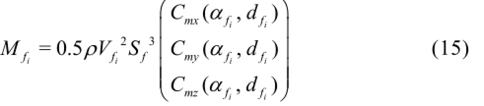
The terms (Cx,Cy,Cz)are the fin force and moment coefficients,(Cmx,Cmy,Cmz), expressed in fin coordinates. The subscripti=1,2,3,4refers to each fin,Vfiis the velocity of each fin in fin coordinates,andSfis the fin span length. The forces and moments in each fin coordinate are transformed to bodyfixed coordinates using the rotation matrix, as follows:
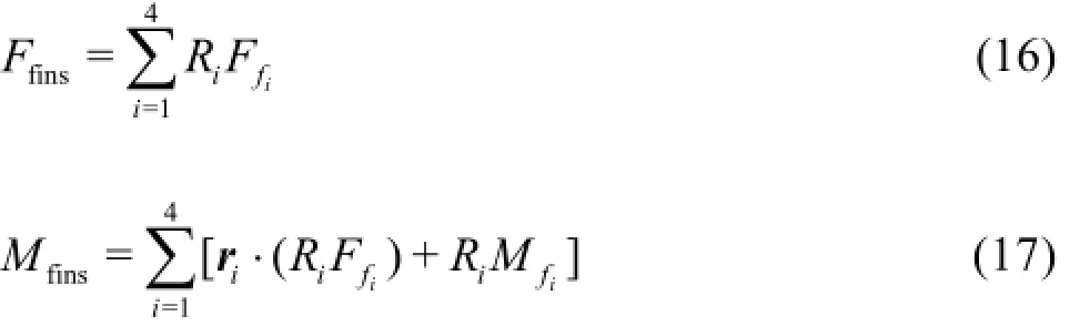
where Riis the rotation matrix from the fin coordinate ito the body-fixed coordinate, as determined by the fin deflection angleδf, and riis the moment arm between the coordinate origin of each fin and the center of gravity. The angle of attack of the fin can be calculated from its deflection angle and the velocity in fin coordinates, as follows:

where Vfis the velocity vector at the coordinate origin of the fin expressed in body-fixed coordinates, and lfis the position vector from the center of gravity to the coordinate origin of the fin.
1.6 Forces acting on wetted body
In the case of partial cavitation, the vehicle body extends beyond the cavity closure point. The wetted area and volume of the body can be easily calculated by utilizing the cavity profile. The hydrostatic forcesand moments are the buoyancy forces and moments as calculated using (20) and (21), respectively.

Here,(φ,θ,ψ)are the Euler angles,Bwetis the magnitude of the buoyancy and given byBwet=ρgVwet,andXbuoy=[xb,yb,zb]Tis the position vector from the center of gravity to the center of buoyancy.

Fig.9 Hydrodynamic forces acting on XB-axis
The hydrodynamic forces acting on the wetted area are the pressure drag, frictional drag, and forces caused by the added mass. The hydrodynamic forces are calculated in two directions: the XB-axis and YB,ZB-axis. This is because, for a supercavitating vehicle, the hydrodynamic forces acting on the sectional shape are the same as those acting along theXBaxis(YB-ZBplane). Figure 9 shows the hydrodynamic forces acting on theXB-axis. The pressure drag and forces that are caused by the added mass and which act on the cavitator are included in the cavitator model. The normal pressure contributions along the wetted body are assumed to have x-axis symmetry, further, it is assumed that the pressure drag exists only at the cavitator. The viscous contributions to the frictional drag coefficient(CF)along the wetted portion of the body are calculated by using the Hughes line for the friction coefficient[20], thus, (22) expresses the frictional drag on the wetted body.
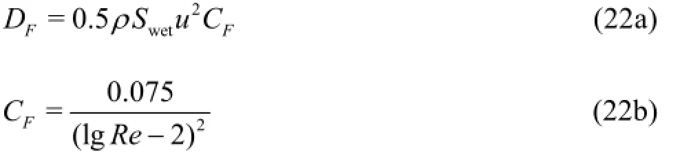

DFis the magnitude of the friction drag that acts against the forward motion of the body,Re is the Reynolds number, andρis the fluid density. The hydrodynamic force acting on the YB-ZBplaneis calculated by Morison’s equations[20], as follows (Eqs.(23) and (24)): Fmorisonis calculated by integrating dFmorison, which is the differential hydrodynamic force acting on the wetted part of the vehicle body. Then,dsis the differential length along theXB-axis,FIis the force proportional to the acceleration,FDis the force proportional to the square of the velocity, which is the sum of the friction drag and pressure drag,Cmand CDare the added mass and drag coefficients (1 and 1.3, respectively) for the cylindrical section, andV and V˙ are the velocity and acceleration, respectively, of the flow in the YB-ZBplane relative to the body. The moment generated by the force in Eq.(23) can be written as follows

where lh,cis the distance from the center of gravity to the hydrodynamic center ofFmorisonalong the XB-axis, and Fmorison,yand Fmorison,zare the YB-and ZB-axes components of Fmorison, respectively.
The total forces and moments acting on the wetted body can thus be written as follows:


Fig10 Planing of body on cavity wall
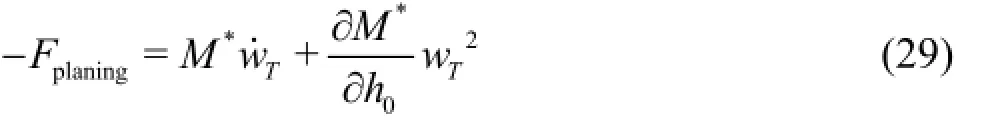
1.7 Planing force model
The planing of the body on the cavity generates forces and moments. The planing force is the interaction force between the vehicle transom and cavity wall. The planing force model was investigated by[21,22]. In this paper, the model developed in Ref.[22]is employed because it fits the experimental data better[23]. Figure 10 shows the planing of a body on the cavity wall. The coordinateζis at a distance along the XB-axis from the transom.αDis the planing angle and h0is the immersion depth when ζ=0,this is the maximum immersion depth. The apparent mass per unit length can be calculated using Eq.(28).
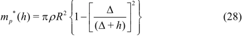
Here,∆is the gap between the body and cavity radius, i.e.,∆=Rc-R,h is the immersion depth.
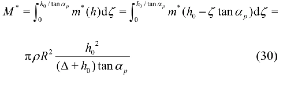
Using the apparent mass per unit length, the planing force is as follows[23]
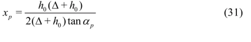
Here,wTis the transom velocity, which is equal to the immersion velocity of the body into the cavity wall, andM∗is the apparent mass, which is expressed as follows
The planing moment can be obtained by calculating the center of pressure of the planing force,xD
In this planing model, several conditions are assumed. The immersion velocity is constant, the planing is steady, and the gap has a positive small value,∆>0,∆≪R.
2. Numerical Simulation
2.1 Ventilated cavity simulation
The modeling of a ventilated cavity was performed in Section 1.3, and the numerical simulation results are given in this section. Figure 11 shows the cavitation number and cavity size of a ventilated cavity according to the ventilation rate CQ. It is clear that the cavitation number decreases and that the cavity size(both radius and length) increases with the ventilation rate. The slope of the plot in Fig.11 is slightly different before and after t =0.3. This is caused by a change in the gas leakage regime from a toroidal vortex to a twin vortex. Figure 12 shows the cavitation number change for the ventilation rate as well as the Froude number. The cavitation number becomes small enough to encompass the vehicle body as a result of supplying gas or attaining a high vehicle speed. A ventilation rate of zero corresponds to natural cavitation.2.2 Open loop simulation
Fig.11 Cavitation number according to ventilation rate and Froude number varying
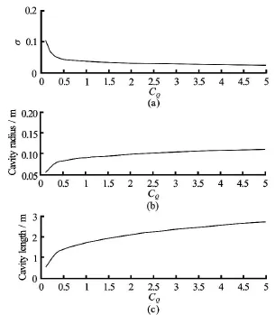
Fig.12 Ventilated cavitation number and cavity size
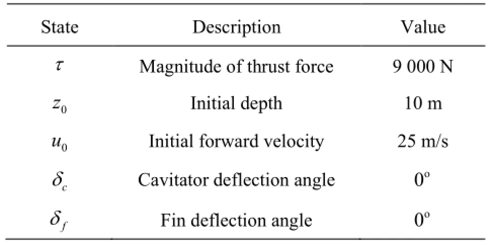
Table 1 Conditions for numerical simulation

Fig.13 Open-loop time responses of integrated model
Open loop simulations of the integrated model were performed to analyze the characteristics of the system and validate the modeling. The vehicle parameters are listed in Table 1, these are based on the benchmark high-speed supercavitating vehicle model used by Ref.[1]. Figure 13 shows the open-loop time response of the integrated model. The simulation conditions are listed in Table 1.
The variables shown in the figure are vertical plane variables because the lateral plane variables are constant and equal to zero. Here,xandz are the XEand ZEpositions, respectively, in the earth-fixed frame, while anduandw respective are the velocities.θis the pitch angle andqis the angular velocity. The pitch angle of the vehicle negatively increases until90o, because the fins (elevators in this case) and the cavitator generate a negative pitch moment. The forward speed is always positive due to the thrust force, and the heave velocity is also always positive due to the effect of gravity. Therefore, the angle of attack of the cavitator and theZB-axis force are positive according to Eqs.(12) and (13), respectively,and the cavitator generates a negative pitch moment. Similarly, the fins generate a negative lift force and moments. The angle of attack of the cavitator and the fins falls to zero when the pitch angle reaches-90o,this implies that the forward velocity of the vehicle is in the same direction as gravity and therefore, the pitch moment also becomes zero.
Figure 14 shows the cavity radius and length according to the cavitation number. In the initial stages, the cavitation number is relatively small and the cavity is developed. The growth of the cavity reduces the wetted area of the body as well as the frictional drag. Therefore, the forward speedu rapidly increases in the initial state. The drag coefficient of the cavitator is a minimum when the cavitation number is zero and increases with the cavitation number (Eq.(10)). The maximum drag coefficient,CD,max, is 1.17 in this study,which is identical to the disk drag coefficient in water. Hence, the forward speed converges to a constant value (approximately 106 m/s), and the drag coefficient reaches a maximum.

Fig.14 Cavity profile versus cavitation number

Fig.15 Immersion depth and attack angle of fin
The immersion depth and attack angle of the fin are shown in Fig.15. The immersion depth decreases to 93% when the radius of the cavity is a maximum. The angle of attack is calculated from Eqs.(18) and(19), and its sign is mostly positive; it reaches zero when the pitch angle reaches -90o.
It is clear that the vehicle states diverge when not controlled. The depth, especially, should be controlled to maintain the supercavitating condition. However,the design of the controller falls outside the scope of this research. Therefore, we performed a 1-DOF numerical simulation of the supercavitating vehicle. The magnitude of the thrust force is much less than that obtained in the previous simulation,T=3000N,which is not enough to enable the creation of a supercavity. Instead, the ventilated cavity is used to create the supercavity. The ventilation rateCQis 0.1 before t=3. In this condition, the ventilation rate is still not sufficient to enable supercavitation. Aftert=3, the ventilation rate continues to increase with a slope of 0.5t.
Figure 16 shows the 1-DOF simulation results for the supercavitating body. Sequentially from top to bottom, the forward speed, forces acting on the cavitator,and vehicle body are shown. The cavity length and radius are shown in Fig.17. These values are not sufficient to enable the enveloping of the entire vehicle body withCQ=0.1before t =3. This means that the vehicle is in the partially cavitating condition. Therefore, the value of the force acting on the body,Fwet,is negative and not zero. Therefore, the forward speed is less than 60 m/s, which is less than the maximum vehicle speed required to establish the supercavitating condition. Aftert=3, the cavity size increases sufficiently to envelop the vehicle body as the ventilation rate increases. As the cavity size grows, the wetted area of the body is totally eliminated, becoming zero at aboutt=4. Therefore, the forward speed also increases and reaches a maximum.
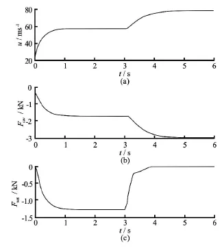
Fig16 Forward velocity and hydrodynamic force with ventilation
3. Conclusion
In this study, we constructed a 6-DOF equation of motion for a supercavitating vehicle system with the aim of modeling a ventilated supercavity conside-ring the cavity closure type. A 6-DOF equation of motion was constructed by defining the forces and moments acting on the supercavitating body. Each part of the vehicle was modeled by referring to previous research, and we integrated the different models to obtain the dynamics of a supercavitating system. We also modeled the relationship between the cavitation number and the ventilation rate according to the cavity closure type. Finally, by using the numerical simulation results, the physical characteristics of the supercavitating vehicle are analyzed and the modeling completeness is validated. Numerical simulation results show that the cavity size increases with the ventilation rate and that pitch control is required to make the vehicle stable and maintain the vehicle’s depth. The results of a 1-DOF simulation show that the vehicle can attain the supercavitating condition in spite of a “small thrust force” through the application of ventilation. Ventilation is an effective way of eliminating the wetted area of the body and helps to reach the supercavitating condition in the initial phase of flight. Our research results can be used to understand and employ ventilated supercavitating vehicle systems. Our future research will address the design of a controller for a ventilated supercavitating system, including attitude control using control surfaces and gas supply rate control to maintain the desired cavitation number.
Acknowledgments
This work was supported by the Basic Science Research Program through the National Research Foundation of Korea (NRF), the Ministry of Education, Science and Technology (Grant No. NRF-2012R1A1A2008633). It was also supported by the Civil-Military Technology Cooperation Program funded by the Civil-Military Technology Cooperation Center (CMTC) (Grant No. 14-BR-EN-31).
References
[1] DZIELSKI J., KURDILA A. A benchmark control problem for supercavitating vehicles and an initial investigation of solutions[J]. Journal of Vibration and Control, 2003, 9(7): 791-804.
[2] VANEK B., BOKOR J. and BALAS G. J. and ARNDT R. E. A. Longitudinal motion control of a high- speed supercavitation vehicle[J]. Journal of Vibration and Control, 2007, 13(2): 159-184.
[3] DZIELSKI J. Longitudinal stability of a supercavitating vehicle[J]. Journal of Oceanic Engineering, 2011,36(4): 562-570.
[4] FAN H., ZHANG Y. and WANG X. Longitudinal dynamics modeling and MPC strategy for high-speed supercavitating vehicles[C]. Electric Information and Control Engineering (ICEICE), International Conference on IEEE. Wuhan, China, 2011, 5947-5950.
[5] GARABEDIAN P. Calculation of axially symmetric cavities and jets[J]. Pacific Journal of Mathematics,1956, 6: 611-684.
[6] LOGVINOVICH G., SEREBRYAKOV V. On methods of calculating a shape of slender axisymmetric cavities[J]. Gidromehanika, 1975, 32: 47-54.
[7] MAY A. Water entry and the cavity-running behavior of missiles[R]. Final Technical Report NAVSEA Hydroballistics Advisory Committee, Silver Spring,Maryland, USA, 1975, 76.
[8] VARGHESE A. N., UHLMAN J. S. and KIRSCHNER I. N. Numerical analysis of high-speed bodies in partially cavitating axisymmetric flow[J]. Journal of Fluids Engineering, 2005, 127(1): 41-54.
[9] CAMPBELL I., HILBORNE D. Air entrainment behind artificially inflated cavities[C]. Proceedings of the Second Symposium on Naval Hydrodynamics. Washington DC, USA, 1958.
[10] SPURK J. On the gas loss from ventilated supercavities[J]. Acta mechanica, 2002, 155(3-4): 125-135.
[11] SEMENENKO V. N. Artificial supercavitation. physics and calculation[R]. VKI/RTO Special Course on Super Cavition. Von Karman Institute for Fluid Dynamics,Brussels, Belgium, 2001.
[12] KINZEL M., LINDAU J. and KUNZ R. Air entrainment mechanisms from artificial supercavities: Insight based on numerical simulations[C]. Proceedings of the 7th International Symposium on Cavitation, CAV 2009-No. 136. Ann Arbor, Michigan, USA, 2009.
[13] ZOU Wang, YU Kai-ping and WAN Xiao-hui. Research on the gas-leakage rate of unsteady ventilated supercavity[J]. Journal of Hydrodynamics, 2010, 22(5): 778-783.
[14] SAVCHENKO Y. N. Investigation of high speed supercavitating underwater motion of bodies, high-speed motion in water[R]. AGARD Report 827, 20-1-20-12,1998.
[15] KAWAKAMI E., ARNDT R. E. Investigation of the behavior of ventilated supercavities[J]. Journal of Fluids Engineering, 2011, 133(9): 091305.
[16] PARYSHEV E. Theoretical investigation of stability and pulsations of axisymmetric cavities[J]. Trudy TsAGI, 1978, 1907: 17-40.
[17] MAY A. Water entry and the cavity-running behavior of missiles[R]. NAVSEA Hydrodynamics Advisory Committee, Report TR 75-2, 1975.
[18] KIRSCHNER I. N. et al. Control strategies for supercavitating vehicles[J]. Journal of Vibration and Control,2002, 8(2): 219-242.
[19] UHLMAN J. S., FINE N. E. and KRING D. C. Calculation of the added mass and damping forces on supercavitating bodies[C]. Fourth International Symposium on Cavitation. Pasadena, CA, USA, 2001.
[20] NEWMAN J. N. Marine hydrodynamics[M]. Cambridge, MA, USA: MIT Press, 1977, 31.
[21] LOGVINOVICH G. V. Some problems in planing surfaces[J]. Trudy TsAGI, 1980, 2052: 3-12.
[22] VASIN A. D., PARYSHEV E. V. Immersion of a cylinder in a fluid through a cylindrical free surface[J]. Fluid Dynamics, 2001, 36(2): 169-177.
[23] DZIELSKI J. Experimental validation of planing models for supercavitating vehicles[C]. Proceeding of the Undersea Defense Technology Pacific. San Diego, CA,USA, 2006.
10.1016/S1001-6058(15)60538-8
(February 16, 2015, Revised March 16, 2015)
* Biography: KIM Seon-Hong (1987-), Male,Ph. D. Candidate
KIM Nakwan,E-mail: hwkim@snu.ac.kr

- 水动力学研究与进展 B辑的其它文章
- Classification of flow regimes in gas-liquid horizontal Couette-Taylor flow using dimensionless criteria*
- Effect of structure parameters of the flow guide vane on cold flow characteristics in trapped vortex combustor*
- MHD flow of a visco-elastic fluid through a porous medium between infinite parallel plates with time dependent suction*
- Polymer flow through water- and oil-wet porous media*
- Numerical analysis of the unsteady behavior of cloud cavitation around a hydrofoil based on an improved filter-based model*
- Thermal instability and heat transfer of viscoelastic fluids in bounded porous media with constant heat flux boundary*