
Laboratory model study of the effect of aeration on axial velocity attenuation of turbulent jet flows in plunge pool*
2015-12-01 02:12DENGJun邓军ZHANGFaxing张法星TIANZhong田忠XUWeilin许唯临LIUBin刘斌WEIWangru卫望汝StateKeyLaboratoryofHydraulicsandMountainRiverEngineeringSichuanUniversityChengdu610065Chinamaildjhao2002scueducn
水动力学研究与进展 B辑 2015年6期
关键词:刘斌
DENG Jun (邓军), ZHANG Fa-xing (张法星), TIAN Zhong (田忠), XU Wei-lin (许唯临), LIU Bin (刘斌),WEI Wang-ru (卫望汝)State Key Laboratory of Hydraulics and Mountain River Engineering, Sichuan University, Chengdu 610065,China, E-mail:djhao2002@scu.edu.cn
Laboratory model study of the effect of aeration on axial velocity attenuation of turbulent jet flows in plunge pool*
DENG Jun (邓军), ZHANG Fa-xing (张法星), TIAN Zhong (田忠), XU Wei-lin (许唯临), LIU Bin (刘斌),WEI Wang-ru (卫望汝)
State Key Laboratory of Hydraulics and Mountain River Engineering, Sichuan University, Chengdu 610065,China, E-mail:djhao2002@scu.edu.cn
(Received November 2, 2013, Revised April 12, 2014)
In the laboratory model experiment, the velocities of the jet flow along the axis are measured, using the CQY-Z8a velocity-meter. The velocity attenuations of the jet flow along the axis under different conditions are studied. The effects of the aeration concentration, the initial jet velocity at the entry and the thickness of the jet flow on the velocity attenuation of the jet flow are analyzed. It is seen that the velocity attenuation of the jet flow along the axis sees a regular variation. It is demonstrated by the test results that under the experimental conditions, the velocity along the axis decreases linearly. The higher the air concentration is, the faster the velocity will be decayed. The absolute value of the slopeK increases with the rise of the air concentration. The relationship can be defined as K=ACa+Kb. The coefficientAis 0.03 under the experimental conditions. With the low air concentration of the jet flow, the thinner the jet flow is, the faster the velocity will be decayed. With the increase of the air concentration, the influence of the thickness of the jet flow on the velocity attenuation is reduced. When the air concentration is increased to a certain value, the thickness of the jet flow may not have any influence on the velocity attenuation. The initial jet velocity itself at the entry has no influence on the variation of the velocity attenuation as the curves of the velocity attenuation at different velocities at the entry are practically parallel, even coinciding one with another. Therefore, improving the air concentration of the jet flow and dispersing the jet flow in the plunge pool could reduce the influence of the jet flow on the scour.
jet flow, air concentration, velocity
Introduction0F
With respect to the funds, the ski-jump energy dissipation prevails among considerations of the hydraulic projects with high head and large discharge locating in the alp valleys. The energy dissipation is always a major issue in hydraulic engineering. Experiments conducted previously provide an understanding of the factors affecting scouring, such as the tailrace,the density and the Froude number[1-5]. Some studies show that the scour geometry is affected by the characteristics of the jet flow[6,7]. Canepa and Hager[7]showed that the scour depth is decreased significantly by the addition of air to the jet. Deng[8,9]did a series of experiments about aerated jet flows with different air concentrations. He indicated that the air entrainment can reduce the impinging pressure at the pool bottom. However, with the increase of the air content in the jet flow, the maximum fluctuation pressure increases. Duarte et al.[10]studied the influence of the air entrained by water jets on the dynamic pressures applied on the bottom of a plunge pool. Pagliara and Palermo[11]showed that the presence of the air in the jets deeply affects the scour morphology, and the scour geometry was analyzed and compared with the respective obtained in black water conditions. Chanson[12]studied the air-water flow characteristics close to the jet nozzle in pools at small velocities. Bollaert and Schleiss[13]compared wall pressure measurements at the pool bottom. Manson et al.[14]presented experimental studies for turbulent high-velocity jets plunging in a water pool with a flat bottom. It is shown that the impactpressures under the jet have a negative skewness in shallow pools and a positive skewness in deep pools. Melo[15]documented the impact conditions of submerged water jets with artificial air entrainment for velocities of 10 m/s. His experiment shows that the air entrainment reduces the mean impact pressure. Some theoretical expressions has been developed to estimate the aeration effect on the jet flows[16-18]. In overall, different relevant topics were approached for the aerated jet flow in plunge pools, but there is still not a comprehensive analysis of the velocity attenuation of the aerated jet flow in limited-depth pools. This paper presents a series of experimental studies of the aerated jet flow. The effects of the initial velocity, the air concentration and the initial jet thickness are analyzed, respectively, for a further understanding of the velocity characteristics of the aerated jet flow.

Fig.1 Layout of experimental setup
1. Experimental setup
The experiments are carried out at State Key Laboratory of Hydraulics and Mountain River Engineering of Sichuan University. There are a relatively large number of cascade reservoirs. To measure the velocity of the aerated jet flow, an experimental facility is used,as shown in Fig.1 with a rectangular glass flume of 3.5 m×0.25 m×0.8 m. An air-compressor and an air flow-meter are used to provide and control stable air. The air concentration varies from 0 to 0.2. The place of a honeycomb grid (with diameter d=0.001m),immediately upstream of the bend, is the air entrainment region to improve the homogeneity of the flow over the section. These features are to improve the jet flow stability. The diameter of air bubbles in the airwater jet flows are in the range of 0.001 m-0.002 m. The jet outlet is rectangular, with a nozzle exit of 0.22 m×0.02m. The incident angle of the jet flow is 60o. Eight gauging points are placed along the jet axis(defined as x direction, and at the nozzle entry, x=0 m) from A to H at intervals of 0.06 m, and the velocity at each gauging point is measured. The gauging Point A is 0.01 m (x=0.01m)away from the nozzle exit along the jet axis, and the velocity measured at Point A is considered as the initial velocity of the jet flow under each working condition.

Fig.2 Sketch of the double-tip conductivity probe
The velocities of the jet flow along the axis are measured using the CQY-Z8a velocity-meter. The airwater velocities are recorded by using a double-tip conductivity probe (Fig.2). The probe consists of two identical tips with an internal concentric electrode made of platinum and an external stainless steel electrode of 200 µm in diameter. The two tips are aligned in the flow direction and the distance between the two tips isdl (0.01 m). The cross-correlation function between the signals from the two tips assumes the maximum value for the average time dttaken for an air bubble interface to travel from the first tip to the second tip. The velocity at each gauging point (from A to H) is deduced from the time delay between the signals from the two tipsdt and the two-tip separation distancedl.
The velocity along the axial way is measured in the test for different initial velocities VA, different air concentrations Ca(2%, 5%, 10%, 15%, 20%), and different thicknesses of the jet flow b(0.02 m, 0.03 m, 0.04 m). The detailed data about each working condition (37 groups in all) are shown in Table 1.
2. Velocity attenuation along axial way for different initial velocities at entry
The experimental velocity attenuations for different jet velocities at the entry along the way are shown in Fig.3. The relative velocity attenuation value V/ VBis defined as the velocityV at each gauging point over the velocity VBat the nozzle exit. The VAmeasured at the gauging Point A is the initial velocity at the entry. It can be seen that, for different initial velocities at the entry, the velocity along the axis decreases linearly. As the curves of the velocity attenuation for different velocities at the entry are practically the same, the initial jet velocity itself at the entry has noinfluence on the variation of the velocity attenuation. When b =0.02 mand Ca=2%, as shown in Fig.3(a),the absolute value of the slope K of the velocity atte-
nuations is almost the same where VA=3.15 m/s, 4.02 m/s, 5.83 m/s, respectively. This can also be seen under other working conditions, as shown in Figs.3(b)-3(d). In this paper, because the initial velocity has no influence on the variation of the axial velocity attenuation of the jet flows, the average value of V/ VBfor different initial velocities at the entry with the same air concentration and thickness of the jet flow can be used to reduce the measurement error.

Table 1 Experimental working conditions
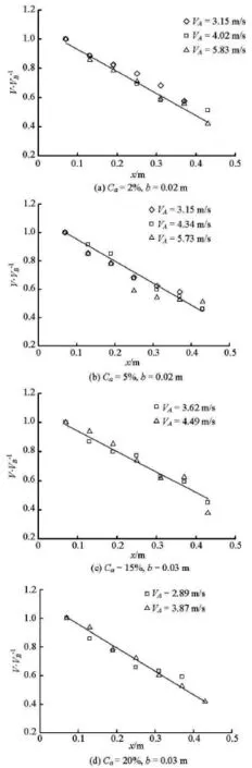
Fig.3 Velocity attenuation of jet flow along the axis for different jet velocities at entry

Fig.4 Velocity attenuation of jet flow along the axis for different aeration concentrations
3. Velocity attenuation along axial way for different air concentrations
The experimental velocity attenuation for different air concentrations along the way is shown in Fig.4. Each figure is for a certain thickness of the jet flowb. The measurement data of V/ VBare the average value of V/ VBfor different initial velocities at the entry, because the initial velocity has no influence on the variation of the velocity attenuation along the axial way when the thickness of the jet flow and the air entrainment conditions are the same.
It can be seen, as a whole, the values of V/ VBdecrease very fast as the values of the air concentration increase. When b=0.02 m, the absolute value of the slopeK of the velocity attenuation increases from 0.0150 to 0.0209 with the air concentration of the jet flow increasing from 2% to 20%. The value of K is increased by 39.33%. When b =0.03m, theK increases from 0.0112 to 0.0163 with the air concentration increasing from 2% to 20%. The K is increased by 45.54%. When b =0.04 m, theKincreases from 0.0091 to 0.0143 with the air concentration increasing from 2% to 20%. TheK is increased by 57.14%.
The results show that the improvement of the air concentration can accelerate the velocity attenuation of the jet flows along the way. There are two possible mechanisms for the air entrainment to affect the velocity attenuation of the jet flows. The first one is, the jet flow has a good air carrying capacity when the velocity is high. The aerated jet flow can be seen as a continuous medium. The density of the aerated jet flow is lower than that of water in the flume. The buoyancy force acts as a resistance to the movement of the aerated jet flow. When the air concentration of the jet flow increases, the buoyancy effect becomes more significant. The other one is, in the experiments, the air bubbles in the aerated jet flow would spill over in a great amount. This movement of air bubbles may destroy the configuration of the jet water. With the increase of the air concentration of the jet flow, the turbulent motion becomes more severe. Therefore, the energy dissipation may become greater along the way. So, the improvement of the air concentration of the jet flow may reduce the influence of the jet flow on the scour.

Fig.5 The relationship between CaandKfor different values ofb
Figure 5 depicts the relationship between the air concentration of the jet flow and the absolute value of the slopeK for a certain value ofb. The analysis of the data indicates that, for a certainb, theK increases linearly with the increase of Ca. ThisKis best correlated by

whereA is a coefficient and Kbis the absolute value of the slope for a certain bwhen Ca=0.Kbvaries with the thickness of the jet flow at the entry. The coefficientA is about 0.03, as deduced from the data under the working conditions for the three different values of b.
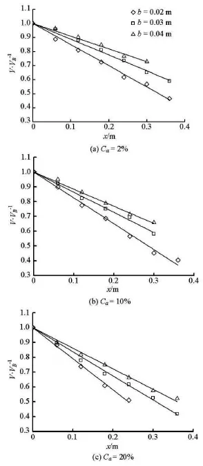
Fig.6 Velocity attenuation of jet flow along the axis for different thicknesses of jet flow
4. Velocity attenuation along axial way for different thicknesses of jet flow
Figure 6 shows the velocity attenuation of the jet flow along the axis for different thicknesses of the jet flow and a given Ca. It can be seen that for a certain air concentration of the jet flow, the velocity along the axial way decays slower with the increase of the thickness of the jet flow at the entry.
When Ca=2%, the absolute values of the slope of the velocity attenuation curve Kare 0.0150, 0.0112 and 0.0091 for b =0.02 m,b =0.03mand b =0.04 m, respectively. Taking theK when b= 0.02 m as a standard reference, the ratio relationship is 1: 0.747: 0.607. This shows the margin of the velocity attenuation whenb increases. The velocity along the axial way decays slower with the increase of the thickness of the water flow. This result shows that the ratio of the shearing dissipation area is the most important element in the energy dissipation in the plunge pool. Under a certain working condition, when the thickness of the water flow decreases, the hydrodynamic radius diminishes. This makes the shearing area of the water flow increase, comparing with the transverse section. Therefore, the energy diffuses rapidly, and the velocity attenuation quickens as well.

Fig.7 The relationship betweenband K/ Kb=2for different values of Ca
When Ca=10%, the values ofKare 0.0175,0.0133 and 0.0116 for b =0.02 m,b =0.03mand b =0.04 m, respectively. Taking the K when b= 0.02 m as a standard reference, the ratio relationship is 1:0.760:0.6763. When Ca=20%, the values ofK are 0.0209, 0.0163 and 0.0143 for b =0.02 m,b= 0.03 m and b=0.04 m. And the radio relationship is 1: 0.780: 0.684. This shows that the differences ofK between a thicker water flow and a thinner water flow are reduced with the increase of the air concentration of the jet flow, as shown in Fig.7. This means that when the air concentration of the jet flow increases to a certain value, the thickness of the water flow maynot have effects on the velocity attenuation along the axial way.
This conclusion is obviously different from that of the non-aerated jet flow. Because the experiments are conducted under artificial aeration conditions and the velocity is not large enough, the air concentration of the jet flow cannot be very high. There is a very special situation. With the increase of the air concentration, the water flow may be discontinuous, just like raining at sea. Raining can be seen as a jet flow with a very high air concentration. For a certain rainfall intensity, the velocity attenuation of the raindrops does not vary no matter how the area of rain changes.
5. Conclusions
(1) In this paper, the velocity along the axis decreases linearly. For a certain thickness and a concentration of the jet flow, the initial jet velocity itself at the entry has no influence on the variations of the velocity attenuation along the axial way.
(2) For a certain thickness of the jet flow, the improvement of the air concentration can accelerate the velocity attenuation of the jet flows along the way. The relationship can be defined as K=ACa+Kb. The coefficientA is 0.03 under the experimental conditions.
(3) The differences of Kbetween a thicker water flow and a thinner water flow are reduced with the increase of the air concentration of the jet flow. The thickness of the water flow may not have effects on the velocity attenuation along the axial way when the air concentration of the jet flow increases to a certain value.
[1] MELO J. F., PINHEIRO A. N. and RAMOS C. M. Forces on plunge pool slabs: Influence of joints location and width[J]. American Society of Civil Engineers,2014, 132(1): 49-60.
[2] LI A., LIU P. Mechanism of rock-bed scour due to impinging jet[J]. Journal of Hydraulic Research, 2010,48(1):14-22.
[3] SARKAR A., DEY S. Review on local scour due to jet[J]. International Journal of Sediment Research,2004, 13(9): 210-238.
[4] PAGLIARA S., HAGER W. H. and MINOR H. E. Hydraulics of plane plunge pool scour[J]. Journal of Hydraulic Engineering, ASCE, 2005, 132(5): 450-461.
[5] PAGLIARA S., AMIDEI M. and HAGER W. H. Hydraulics of 3D plunge pool scour[J]. Journal of Hydraulic Engineering, ASCE, 2008, 134(9): 1275-1284.
[6] AZAMATHULLA H. M., GHANI A. A. and ZAKARIA N. A. Genetic programming to predict ski-jump bucket spill-way scour[J]. Journal of Hydrodynamics,2008, 20(4): 477-484.
[7] CANEPA S., HAGER W. H. Effect of jet air content on plunge pool scour[J]. Journal of Hydraulic Engineering, ASCE, 2003, 129(5): 358-365.
[8] DENG Jun, XU Wei-lin and QU Jing-xue et al. Influence of aeration on scouring[J]. Journal of Hydraulic Engineering, 2002, 10(1): 8-13(in Chinese).
[9] DENG Jun, XU Wei-lin and LIU Shan-jun et al. Influence of water ject aeration on pressure in scour pool and plunge pool[J]. Advanced in Water Science, 2009,20(3): 373-378(in Chinese).
[10] DUARTE R., SCHLEISS A. J. and PINHEIRO A. Influence of jet aeration on pressures around a block embedded in a plunge pool bottom[J]. Environmental Fluid Mechanics, 2015, 15(1): 1-21.
[11] PAGLIARA S., PALERMO M. Analysis of scour characteristics in presence of aerated crossing jets[J]. Australian Journal of Water Resources, 2013, 16(2):163-172.
[12] CHANSON H., AOKI S. and HOQUE A. Physical modeling and similitude of air bubble entrainment at vertical circular plunging jets[J]. Chemical Engineering Science, 2004, 59(4): 747-758.
[13] BOLLAERT E. F. R., SCHLEISS A. J. Scour of rock due to the impact of plunging high velocity jets[J]. Journal of Hydraulic Research, 2003,41(5): 465-480.
[14] MANSON P. A., BOOLLAERT E. F. R. and SCHLESIS A. J. Impact pressures of turbulent high-velocity jets plunging in pools with flat bottom[J]. Journal of Experimental Fluids, 2007, 42(1): 49-60.
[15] MELO J. F. Reduction of plunge pool floor dynamic pressure due to jet air entrainment[C]. International Workshop of Rock Scour: Rock Scour Due to Falling High-Velocity Jets. Lisse, The Netherlands, 2002,125-136.
[16] MAZIAR M., SCGLEISS A. Dynamic analysis of anchored concrete linings of plunge pools loaded by high velocity jet impacts issuing from dam spillways[J]. Dam Engineering, 2010, 20(4): 307-327.
[17] LIU Shan-jun, XU Wei-lin and WANG Wei et al. Aeratiion effect of submerged jet on hydraulic characteristics[J]. Journal of Hydrodynamics, Ser. B, 2002, 14(3):35-39.
[18] MELO J. F., PINHEIRO A. N. Effect of jet aeration on hydrodynamic forces on plunge pool floors[J]. Canadian Journal of Civil Engineering, 2008, 35(5):521-530.
* Project supported by the National Natural Science Foundation of China (Grant Nos. 51179113 and 51379138).
Biography: DENG Jun (1973-), Male, Ph. D., Professor
ZHANG Fa-xing,E-mail: zhfx@scu.edu.cn
猜你喜欢
河南科技(2022年8期)2022-05-31
考试与评价·八年级版(2020年3期)2020-11-02
学苑创造·A版(2019年8期)2019-08-15
——身体的悲剧,人生的喜剧
当代陕西(2018年22期)2018-12-21
东坡赤壁诗词(2018年4期)2018-11-07
艺术生活-福州大学厦门工艺美术学院学报(2016年4期)2016-07-31
现代家长(2016年1期)2016-01-15
中学化学(2015年5期)2015-07-13

- 水动力学研究与进展 B辑的其它文章
- An effective method to predict oil recovery in high water cut stage*
- Impact of bridge pier on the stability of ice jam*
- Implicit large eddy simulation of unsteady cloud cavitation around a planeconvex hydrofoil*
- Prediction of ship-ship interactions in ports by a non-hydrostatic model*
- Flow hydrodynamics in embankment breach*
- The variations of suspended sediment concentration in Yangtze River Estuary*