
Dynamic Simulation Analysis of the Flexible SwapDevice
2015-12-20 09:14CUIYanbo崔艳波ZHAOLasheng赵腊生ZHANGQiangZHANGJianxin张建新
CUI Yanbo(崔艳波),ZHAO Lasheng(赵腊生),ZHANG Qiang(张 强),ZHANG Jianxin(张建新)
Key Laboratory of Advanced Design and Intelligent Computing,Dalian University,Dalian116622,China
Introduction
With the increasing ability in research,development and application of space,many countries have developed and launched a variety of tasks involved with spacecraft.Many enabling technigues have been developed in the past two decades and several technology demonstration missions have been completed[1-3].The structure and composition of spacecraft become more complex and the requirements of the technical performance get higher[4].The important issue for the current space technology has been solved.On-orbit service technology is used for spacecraft,including onorbit refueling,module replacement and on-orbit assembly.The technology can enhance performance,prolong the service life of satellite,reduce the cost and risk,and expand the range of application.
Flexible swap device can effectively enhance the quality of the rail service,reduce investment costs and improve reliability and security of the system.But,maintaining or reparing satellites in orbit is a delicate task that requires expert skills[5].Therefore,the structural design and analysis of the characteristics of flexible plug agencies can improve the use of modeling software and corresponding virtual prototyping technology[6].We can create the design and simulation plug body functions,meet the design requirements of agency system and provide some guidance meaning and a high practical value.
In this paper,the model is established according to the requirements and swap-bodies function.At first,Pro/E is used to build the 3Dgeometric model of organizations and identify the major components and spatial distribution agencies.Then automatic dynamic analysis of mechanical systems(ADAMS)is applied to determining influencing factors by operating dynamics analysis.At last,we can optimize the structure of the model.
1 Research Status of Flexible Swap Devices
For on-orbit assembly operation,the design of module replacement is a basic work and the primary condition.Replaceable modular structure design is mainly embodied in the replaceable modular structure installation mechanism[7].
Replaceable module structure is designed in the form of packaging,which is the main function part of module.In addition,all the components are encapsulated in the standard letter box.Figure 1shows the replaced module overall structure diagram.The module includes function module and control module which are encapsulated inside the package and become standard of replaceable module.
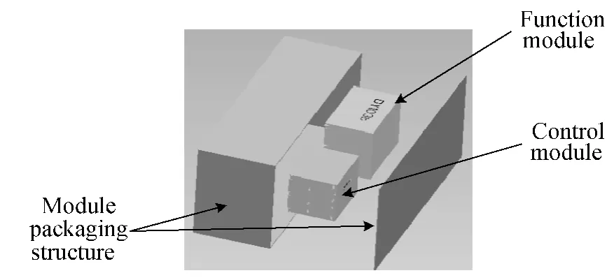
Fig.1 Schematic diagram of the module
The flexible swap device is an important component of replaceable module,whose reliability directly affects the completion of the whole system task.The flexible swap device links the module shell and base and realizes insert and pull of the module replacement.The device consists of modules,module base,gears,racks,compression springs,lock hooks,and guide pins.The form of the flexible swap device docking and separation is determined by the general system requirements.Based on replaceable modules,connected form can be divided into spring connection,the gear-rack connection form,chain link,connecting rod type connection forms and the piston pin type.Spring connection often needs to open the module front cover,including the spring guide slider,compression spring and guide pins.Connection type gearrack consists of gear,transverse rack,longitudinal rack and compression spring.The operation is simple and easy to use,which is the mature technology.However,the mechanism is relatively complex.Chain type interlocking institutions require specialized tensioning device,but the structure is relatively complex which needs the reliability of the chain gear type.Connecting rod type structure is such an inconvenient arrangement which is in large size with complex character that works long time which may affect the accuracy of plug pin.Its use is similar to the mechanical wear.
2 Flexible Swap Device Modeling
2.1 Requirements of design agency
The 3Dgeometry model mechanism describes the relationship between each component entity model static position[8].Each component has six degrees of freedom which are three directions of freedom and three rotation degrees of freedom.In order to get the ideal motion transformation movement relationship of each component,the motion constraints between parts will be applied.Taking the factors of influence on the mechanism into consideration,we add the constraints.The flexible swap device installs on the repair or service spacecraft.Figure 2shows the 3Dsolid model of the flexible swap device.

Fig.2 The solid model of the flexible swap device
2.2 Working principle of the agency
Mainly including movable module,the flexible swap device inserts a new module.Figure 3shows the cutaway view of the flexible swap device.The main structures include locking pin,buffer mechanism,compression spring,locking mechanism,linkage mechanism and locking hook.Working principle of the device is that servicing spacecraft or spacecraft grasps the clamping mechanism linkage with the remote control.The linkage mechanism transfers the forces from the locking device to complete unlock.When the device is unlocked,the mechanical arm drives module free pulling and inserting function.In the whole process,we should make sure of the force in an effective range.
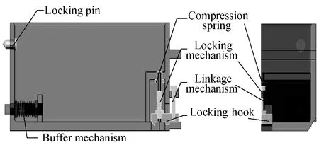
Fig.3 The inner shell structure
3 Dynamic Modeling and Simulation
3.1 Establishment of dynamic model
For the dynamic model,we can establish the system kinematics equation of the Lagrange multiplier method[9-10].

where T,Q,ρ,q,μand·qdenote the kinetic energy of the system,the generalized force,corresponding to the integrity constraints of Lagrange multiplier array,the generalized coordinates of the system array,corresponding to the Nonholonomic constraint Lagrange multiplier array,and the generalized coordinates of the system speed,respectively.And the superscript T denotes the transpose of the variable.
The contact-impact process should take the friction on system convergence effect into account,for the equation is solved mainly by the modified Newton-Euler iterative algorithm.While dealing with contacts-collision phenomenon,we treat them as continuous dynamic problems and determine the collision force by recovery coefficient method of impulse theorem.The flexible swap devices system mainly analyzes the impact of collision on mechanism performance.The collision process is preferentially analyzed when the system collision occurs.The simplifying process of collision model of flexible plugging mechanism is shown in Fig.4.M1,M2,F,K,x,˙x and c denote the inner shell of module,the outer shell of module,the level force exerted by mechanical arm,non-linear function of the relative displacement,the relative displacement,the relative speed and the damping coefficient,respectively.Correct reasonable collision model is the key to solving the problem of impact dynamics system.

Fig.4 Collision model
The normal collision force:

where Fsand Fddenote the spring force and the daming force,respectively.
3.2 Adding constraints and motion
3Dgeometric model is input the material property parameters which import into the dynamic simulation software ADAMS.The model of each component material is set with steel material.After the material attributes is set,software will automatically calculate the centroid,moment of inertia and mark position of center of mass.
The models are added joints and motion based on the work requirements[11-12].The module housing connects a fixed joint to the ground.The guide pin connects a translational joint to the module box.The linkage mechanism connects a translational joint to the guide bolts.While the linkage connects fixed joints with the rod linkage and the locking lever.The buffer connects translational joints with the module housing and the module box.The locking pin of the locking mechanism is connected to the module housing by a fixed joint and to the modules by a translational joint.The model consists of 14rigid bodies,6motion pairs,5fixed sides,2 contact pairs and 2spring dampers and the model has two degrees of freedom.The constraint is shown in Fig.5.
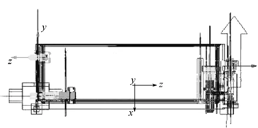
Fig.5 Model motion and joints
3.3 The simulation model of the mechanism
The simulation process mainly includes geometric model,drive mechanism,coordination mechanism and locking mechanism[13].The input parameters and conditions consist of coordinates,geometric parameters,part of the mass,moment of inertia,compression spring and driving force.For the flexible plug mechanism,the whole movement process is implemented in outer space without gravity,which we should set the gravitational acceleration to zero.The spring buffer is installed in the flexible swap device.We can set K=0.1and c=0.8meeting the Hooke's law for spring buffer.The ADAMS/view main functions are the displacement function,velocity,acceleration function,contact function,constraint function,binding function,force function,mathematical functions and data function.This paper mainly adopts the driving function design which force is established by STEP function[14]during the motion process.STEP function used to the mechanical arm is as follows:
(1)the horizontal direction of the drive:
STEP(time,0.4,0,0.9,370)+STEP(time,2.0,0,2.5,-370);
(2)the vertical direction drive:
STEP(time,0,0,0.3,9)+STEP(time,1.2,0,1.5,9)+STEP(time,1.6,0,1.9,9)+STEP(time,2.6,0,2.9,-9).
The kinematic analysis of the flexible swap device system mainly aims at the form of movement and stress conditions in the working process.The working process of inserting mechanism is divided into the unlocking process,the insertion process,the locking process and the pull out process.The mechanical arm with remote control captures the module shell,unlocks the locking device between the shell and the house,pulls out of the inner shell and completes the movement out of the old module.With the help of the mechanical arm,the new module owns the function of inserting into the shell within the module.The buffer module installs in the front of module and the shell contact collision.Buffer action can reduce the mechanical arm force,preventing too high impact on the spacecraft deviated from the normal track.When the inner shell arrives at a certain position,the sensor receives the information and transmits the signal to the central processor.Then the mechanical arm will stop action.The inner shell fixes track and locks system.The whole movement process of this body,trajectory of locking pin and the inner shell centroid are shown in Figs.6and 7.

Fig.6 The trajectory of locking pin

Fig.7 The trajectory of inner shell centroid
The motion trajectory locking pinand locking mechanism are shown in Fig.6in the whole process.Motion trajectory is 9mm.In the unlocking process,the gradual movement is upped.The displacement of trajectory decreases gradually and maintains a gentle curve.In the insertion phase,both pin and displacement stay constants.After the module is fully inserted,the pin returns to the original displacement by the action of the spring.The module locking is fixed at a position.Through the track of pin,we can see that the kinematic condition meets the design requirements.
The track of the inner shell centroid is shown in Fig.7.The trajectory of the center of mass is 390mm.When the structure is in the unlocking state,the inner shell does not move and maintains a constant trajectory at the moment.Along with the body of insertion,the inner shell starts moving.Its trajectory is shown in the insertion process stage.The displacement decreases gradually after insertion and maintains the lock state when it is completed.When the device is pulled out,its track is shown in the figure.The track is also gradually increasing and reaching a constant value,so we can complete the pull out process.From the inner shell centroid trajectory,it can be seen that the structure design of insert draw mechanism meets the design requirements.
Figures 8and 9are the simulation results of the impact force and the collision torque of the swap device spring buffer collision model in a different spring and damping.The contrasts show that the collision force and torque coupled with the deeper level increase in gentle as the damping and spring stiffness become small.The verification of different experiments proves that the figures tend to be a certain amount which is optimal,from which we can see that the flexible swap device installed with buffer can effectively reduce the collision force and energy absorption.Buffers are a result of decrease in the presence of collision between the housing and the outer housing swap within the organization.The impact on the organization system of equations is relatively small.So we select the buffer mechanism with mounted module which is feasible.

Fig.8 Comparison of buffer impact force moment
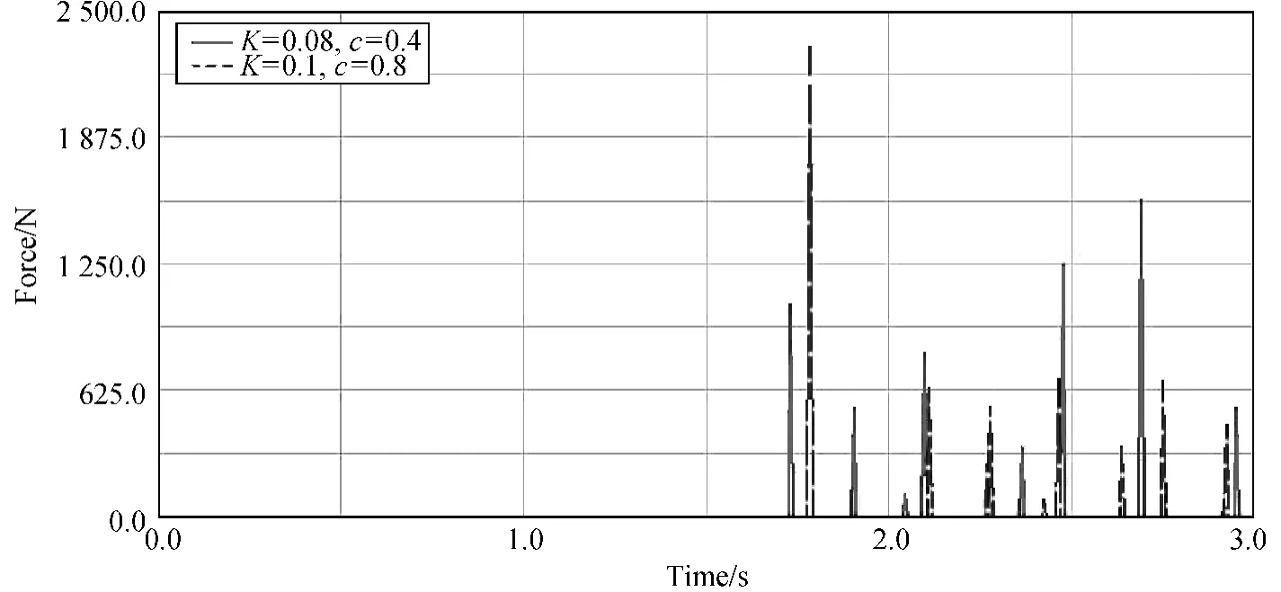
Fig.9 Comparison of buffer impact torque

Fig.10 Force diagram of the guide pins
Figure 10shows the positioning pin is affected by the collision force amplitude in the process of collision.From Fig.10,we can see that the positioning pin on initial contact isn't immediately changed,but has produced a relatively small force and then directly becomes a maximum value.The phenomenon reason is that the positioning pin only plays the positioning and guiding role,rather than reduces the collision force.
4 Conclusions
(1)Through the analyses of the flexible plug mechanism,it can be seen that the mechanism can both reach the design requirements and accord the theoretical system of equations.
(2)The collision model system dynamics equations aim to analyze the effect of model of kinematics equations and collision mechanism in the process and confirm the feasibility of mechanism design.
(3)This paper provides the basis for designing multi-body system and rigid flexible coupling system,creating the flexible swap device and offering reference for stability analysis of mechanism.
[1]Wang D K,Huang P F,Cai J.Coordinated Control of Tethered Space Robot Using Mobile Tether Attachment Point in Approaching Phase[J].Advances in Space Research,2014,54(6):1077-1091.
[2]Hong S B,Na H,Ahn J.Assessment of Architectural Options for a Dual-Mode Disaster Monitoring Constellation Supported by On-orbit Propellant Depots[J].Journal of Aerospace Engineering,2014,228(11):2108-2122.
[3]Aziz S.Development and Verification of Ground-Based Tele-robotics Operations Concept for Dextre[J].Acta Astronautica,2013,86(3):1-9.
[4]Chen X Q,Yuan J P.On-orbit Servicing of Space Systems[M].Bei-jing:China Aerospace Press,2009.(in Chinese)
[5]Wolff R,Preusche C,Gerndt A.A Modular Architecture for an Interactive Real-Time Simulation and Training Environment for Satellite On-orbit Servicing[J].Journal of Simulation,2014,8(1):50-63.
[6]Zhang J Y.Movement Mechanism with Clearance Vice Kinetic Models[D].Xi'an:Xidian University,2006.(in Chinese)
[7]Yu W Y,Ji L H,Jin D W.A Survey of Dynamics Model of Pairs with Clearances in Mechanism[J].Mechanical Science and Technology,2001,20(5):665-668.(in Chinese)
[8]Zeng H,Chen Z T,Wang Z W.Research on the Innovative Design of Mechanism Experimental Platform Based on Pro/E[J].Mechanical Engineer,2012(3):64-65.(in Chinese)
[9]Du Z H,Wang X G,Di C C.Using PRO/E and ADAMS Combined to Create Complex Mechanical System Simulation Mode[J].Machinery,2002,29(S1):64-66.(in Chinese)
[10]Li J.ADAMS Tutorial Examples[M].Beijing:Beijing Institute of Press,2002.(in Chinese)
[11]Liang H,Yu Y Q,Zhang C X.A Dynamic Simulation System for Flexible Robot Manipulators Based on ADAMS &ANSYS[J].Mechanical Science and Technology for Aerospace Engineering,2002,21(6):892-895.(in Chinese)
[12]Chen L P,Zhang Y Q.Mechanical System Dynamics Analysis and ADAMS Application Tutorial[M].Beijing:Tsinghua University Press,2005.(in Chinese)
[13]Ma S J,Liu G,Wu L Y.A Review of the Modular Design Methods for Spacecraft Structure[J].Mechanical Science and Technology for Aerospace Engineering,2011,30(6):960-961.(in Chinese)
[14]Guo A P,Hong J Z,Yang H.Flexible Multi-body System Dynamics Model of Impact Substructure[J].Science in China (Series E),2002,32(6):765-770.(in Chinese)
 Journal of Donghua University(English Edition)2015年2期
- Journal of Donghua University(English Edition)的其它文章
- Analysis of Co3O4/ Mildly Oxidized Graphite Oxide (mGO )Nanocomposites of Mild Oxidation Degree for the Removal of Acid Orange 7
- Ontology-Based Semantic Multi-agent Framework for Micro-grids with Cyber Physical Concept
- A Motivation Framework to Promote Knowledge Translation in Healthcare
- Aircraft TrajectoryPrediction Based on Modified Interacting Multiple Model Algorithm
- Two Types of Adaptive Generalized Synchronization of Chaotic Systems
- A Dependent-Chance ProgrammingModel for Proactive Scheduling