
In fluence of Defects and Crystallographic Orientation on Mechanical Behavior of Nanocrystalline Aluminium∗
2016-05-10 07:38JunCaiQiongDengMinRongAnHaiYangSongandMengJiaSu
Jun CaiQiong DengMin-Rong AnHai-Yang Songand Meng-Jia Su
1School of Aeronautics,Northwestern Polytechnical University,Xi’an 710072,China
2Department of Mechanical Engineering,University of North Carolina at Charlotte,North Carolina 28223,USA
3College of Materials Science and Engineering,Xi’an Shiyou University,Xi’an 710065,China
1 Introduction
In recent years,with the development of nano science and technology,nano materials have attracted more and more attention due to its superior mechanical,electrical,magnetic,optical and chemical macroscopic properties in the aerospace,electronics,metallurgy,chemical,biological,and medical fields.[1]Therefore,understanding the relationship between the nanocrystalline metal microstructure and its mechanical properties,as well as the deformation mechanism is of great significance for the material design in certain application requirements.
Over the past decades,molecular dynamics(MD)simulation is one of the most promising methods,which can be used to investigate internal physical mechanisms of nanostructure by atomic motions in detail.[2−11]
It is well-known that the defects,such as dislocations and voids,may affect the mechanical properties of materials significantly.And a great deal of the researches have been applied to investigate the influence of defects on the materials.Makino et al.[12]simulates void formation in nickle face-centered cubic(fcc)metal using MD method by subjecting in finitely long cylinders to a multiaxial tensile strain field and their work is primarily focused on void nucleation and stable void growth.Potirniche et al.[13]also simulated the void growth and coalescence in single crystal nickel.They had considered the size effects from the nanoscale to the larger scales under tensile loading.Their results showed that the specimen length scale changes the dislocation pattern.Wu et al.[14]reported that the existence of voids resulted in a decrease in elastic modulus of single crystalline materials,and the decreasing amount is almost linearly related to the radius squared of the void.Besides,other researchers also did some investigation about the defect effects.[15−18]
The crystallographic orientation of single crystals shows strong in fluence on the plastic deformation and fracture modes in elongation experiments.[19−22]To evaluate and explain the fundamental mechanisms in the process of the mechanical deformation,Diao et al.[23]used atomistic simulations to study a surface-stress-induced phase in gold nanowires,and found that the emergence of the transformations is controlled by initial orientation.Gao et al.[24]investigated the mechanical properties of copper nanowire(NWs)along h100i,h110i,and h111i crystallographic orientation under tensile loading at different temperatures.They observed that Cu NWs in different crystallographic orientations behaved differently during the deformation,and the Young’s modulus decreased linearly with the increased temperature.
However,little work[13]has been done to analysis the deformation of single-crystal Al in different crystallographic orientations with voids.In this work,one-void and two-void single crystal Al along h100i,h110i,and h111i crystallographic orientation are used to investigate the influence of nano-voids and crystallographic orientation on the deformation under tensile loading of 0.01 K.
The paper is organized as follows.In Sec.2 we describe the simulation method and the models choosed for our study.Section 3 provides the results and discussion.Finally,some conclusions are present in Sec.4.
2 Simulation Models and Methods
Three types of single crystal Al are constructed for analogous simulation,i.e.,h100i,h110i,and h111i oriented single crystal Al,respectively.In order to investigate the void growth and coalescence,we use two types of specimens,as indicated in Fig.1.In both models,the initial voids are introduced by removing the atoms from the perfect crystals.The dimensions of all specimens are about 21 nm×10 nm×2.3 nm.The periodic boundary conditions are applied in all three spatial directions to model a bulk-like structure without free surfaces.All the simulations are running at a constant temperature of 0.01 K.
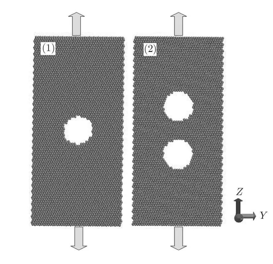
Fig.1 Schematic of a simulated sample used for the simulation.Model 1 represents the specimen with one void,where the specimen 2 is the specimen with two voids.
In this work,MD simulations have been performed with embedded-atom method(EAM)potential developed by Cleri et al.,[25]which provides an effective description of the atomic interactions of Al atoms in the simulation.All the MD simulations are performed using the Verlet integration algorithm with the time step of 3 fs.In order to start the simulation,the system is relaxed for 30 ps in the canonical ensemble(namely,number of atoms,volume,and temperature conservation).This procedure causes the pre-stress to be set to zero in the lattice.Atoms near the surface lose their electrons and obtain a force field different from those of bulk atoms.Therefore it is needed to carry out,which makes atoms to readjust themselves in order to minimize their kinetic energy.[1,26−28]A constant strain of 0.001 is applied to the specimens during the simulation.Here,strain is introduced by uniformly adjusting each atom in y-coordinate during the simulation according to the applied strain rate.[29−30]The common neighbor analysis(CNA)[31]is used to detect the deformation of the microstructure and this is implemented by using the Open Visualization Tool(OVITO).[32]The analysis and classification of each atom according to its environment allow us to identify various deformation mechanisms during tension loading.[15]Here,the hexagonal close-packed(hcp),face-centered cubic(fcc)and non-structured atoms are colored red,green and white,respectively.
3 Results and Discussion
This section presents the results regarding the elastic and plastic deformation of the specimens with one-or two-voids.The effect of anisotropic on elastic and plastic deformation is also investigated in the last part of this section.
3.1 Effect of Voids on Mechanical Properties of the Material
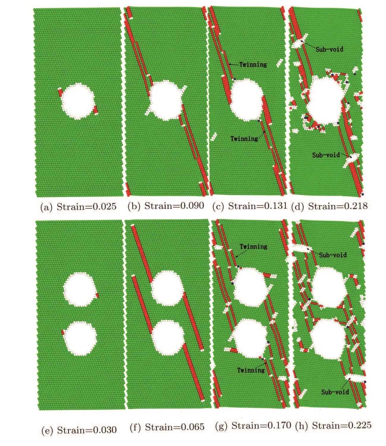
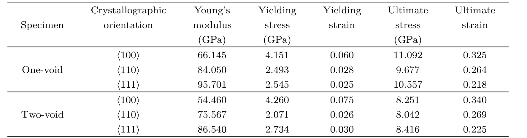
Figure 2 shows the typical stress-strain curves of Al for three different specimens with h111i orientation.As shown in Fig.2,the stress increases linearly with increasing of strain.After an initial elastic range,the dislocations emit from the void surfaces in single-crystal Al(The stress is defined as yield stress at this point),and the Young’s modulus is derived from the stress-strain relationship at a small tensile strain level in the linear elastic regime.Upon further loading,the stress increases unceasingly and a stress drop is observed after the stress peak(at this point,the peak stress is defined as ultimate stress),which implies that a mass of dislocations generate and propagate in the crystal.As presented in Table 1,the Young’s modulus is shown to be Evoid-free>Eone-void>Etwo-voidfor single-crystal Al,while the yield strength to be Svoid-free Fig.2 (Color online)Stress-strain curves for different single-crystal Al with h111i crystallographic orientation at 0.01 K. Table 1 The Young’s modulus,Yielding stress,Yielding strain,Ultimate stress and Ultimate strain for different specimens in h111i crystallographic orientation. Fig.3 Atomic structure con figurations of h111i single-crystal Al under tensile loading at 0.01 K.(a)Strain ε=0.025,the first dislocations are nucleated on the opposite sides of the void;(b)Strain ε=0.090,dislocations generate and emit;(c)Strain ε=0.131 void increases in volume and three-layer twins exist;(d)Strain ε=0.218,the ultimate stress comes;(e)Strain ε =0.303, first nucleation;(f)Strain ε=0.065,dislocation lines emit towards the edge;(g)Strain ε=0.170,four twin bands are observed near the voids;(h)Strain ε=0.225,the ultimate stress comes. Figures 3(a)–3(d)show the atomic con figuration of the nanocrystal Al with one void.As shown in Fig.3(a),the first dislocations are nucleated on the opposite sides of the void due to the stress concentration,which corresponds to the yield strength about 2.545 GPa at the strain of 0.025.With further deformation,it is observed that dislocation emitted from the same location of the void nut on adjacent{111}plane,as shown in Fig.3(b).Besides,some new dislocations are nucleated on the other sides of the void.By increasing the applied strain,more dislocations are initiated from the void and propagate toward the edge of the specimen.At the same time,the void increases in volume and two three-layer twin bands exist(indicated by arrows),as shown in Figs.3(c).Figure 3(d)shows the atomic con figuration of the single crystal Al when the stress peak emerges at about 0.218 strain level.It is shown in Fig.3(d)that the dislocations blunt the propagation of void.Accompanied by the emission of more dislocations,some sub-voids(indicated by arrows in Fig.3(d))emerge and traverse the dislocation lines.These dislocation behaviors clearly indicate that the emergence of the voids make the structure hard to bear the load,higher than the peak stress.We also record the amount of different atoms for single-crustal Al with one void in tensile loading.It is observed that the hexagonal close-packed(hcp)atoms fraction reaches a maximum about 0.086 when the stress peak emerges while the non-structured atoms fraction continues to rise with the increasing strain(implies the continuous generation and propagation of dislocation during the tensile loading). Figures 3(e)–3(h)show the atomic con figuration of the nanocrystal Al with two voids.As shown in Fig.3(e),the dislocations are noticed to nucleate in the voids near the region between the two voids and the uniaxial stress reaches the yield stress of 2.734 GPa at the strain of 0.03.different form one-void specimen,only one region nucleated in each void.But four stacking fault emit from the voids(Fig.3(f)).Two of them emit from the location of nucleation while another two slip in a flash.With further deformation,the dislocations slip towards the edge of the specimen,and some dislocations are observed across the stacking faults in Fig.3(g).Besides,three-layer twin bands are observed near the voids in Fig.3(g)(indicated by arrows).Figure 3(h)shows the atomic con figuration of single-crystal Al at the ultimate stress about 8.416 GPa(at 0.225 strain,which is bigger than value of onevoid specimen).With the increase of strain,as shown in Fig.3(h),new defects are observed and the voids expand to the edge of the structure.Besides,with the accumulation energy increasing,the dislocations are able to transmit through the region between the two voids,starts to collapse to form one large void.It indicates that dislocations emitting across the void,causing the stress drops of the single-crystal Al. The comparison of results between the three models indicates that the defects such as voids weaken the mechanical properties of materials.Stress concentration around the void result in the fracture of the materials easily.Besides,with the increasing amount of voids,both the Young’s modulus and ultimate stress decrease.In the sequential tensile loading process,the twinning and dislocation slip play an important role in the plastic deformation of h111i single-crystal Al. It is suggested from the above study that the voids have a strong influence on the mechanical properties for single-crystal Al.Here,we investigate the anisotropic effects on the mechanical behavior. Figure 4 shows the stress-strain relationship of two different oriented specimens at 0.01 K.As presented in Fig.4,the stress increases linearly with the increasing of strain.After an initial elastic range,the dislocation emit from the void surfaces in single-crystal Al(at this point,the stress is defined as yield stress)and the Young’s modulus is determined by applying a curve to fit the data in the elastic region.Upon further loading,the stress drops after the stress peak(at this point,the peak stress is defined as ultimate stress).As is presented in Table 2,it is clear to see that Eh111i>Eh110i>Eh100ifor single-crystal Al,indicating that the Young’s modulus is strong dependence on the crystallographic direction.The calculated dependence relations are in agreement with Cu monocrystals in atomistic calculation.[24] Table 2 The Young’s modulus,Yielding stress,Yielding strain,Ultimate stress and Ultimate strain for different specimens. In Fig.5,some snapshots are present to investigate the variation of atomic con figuration of the one-void nanocrystal Al with different orientations.For the samples with one void,the first dislocation nucleates near the void at the strain about 0.028 as shown in Fig.5(a).Two parallel dislocations emit and traverse toward the edge of the surface along a{111}slip plane(Fig.5(b)).The second dislocations nucleate near the first nucleation region and emit in parallel with the first dislocations,as shown in Fig.5(c).Besides,a small number of the non-structured atoms emerge near the first nucleation region and emit along the dislocations,which implies voids starting to expand to the boundary.With further loading,the stress peak emerges at the strain of 0.264.The void is going to penetrate the boundary and a large number of the paralleled dislocations slip as shown in Fig.5(d).At the same time,there are some twin bands existing(indicated by arrows in Fig.5(d)).But during the process of the tensile deformation,we do not observe the formation of the sub-voids like the h111i oriented specimen,which indicates the h110i oriented one-void specimen has good malleability than specimen with h111i orientation.The value of the ultimate strain is another evidence,in which the ultimate strain is 0.218 for h111i orientation and 0.264 for one-void specimens with h110i orientation.The h100i oriented specimen with one void is also performed by tensile loading. Fig.4 (Color online)Stress-strain cures for different single-crystal Al at 0.01 K.(a)One-void specimen.(b)Two-void specimen. Four snapshots are presented in Figs.5(e)–5(h).The specimen comprises an elastic portion up to a strain of 0.06 and a value of the yield strength of about 4.151 GPa.As the yield strength is reached first,dislocation nucleate near the void in Fig.5(e).Figure 5(f)shows that the partial dislocations are characterized by a dislocation core loop enclosing hcp stacking faults.So,the ultimate stress of h100i oriented specimen with one void is about 11.092 GPa,which is bigger than the one-void specimens with other orientations.It is demonstrated in Fig.5(g)that the dislocation loops travel with the expansion of void and the accumulation of hcp stacking faults.The hcp stacking faults penetrate the dislocation loops,then emit and slip along a{111}slip plane in the form of dislocations.With the increase of strain,the stress reaches the maximum value.A large number of non-structured atoms and hcp atoms emerge in the specimen and dislocation lines account for a small proportion(Fig.5(h)).But we do not observer clear twinning deformation during the tensile loading and only twinning-like is seen. Also,single-crystal Al with two voids for different loading directions is simulated.The deformed shapes of h110i oriented two-void specimen in tension loading is presented in Figs.6(a)–6(d).Figure 6(a)shows the nucleation of dislocation emerges near the voids due to the stress concentration.With tension loading going on,the dislocation emit and slip towards the surface.The dislocations meet at the surface and a distinct lozenge slip plane is formed in the single-crystal Al.At the same time,another dislocation emits and propagates through the specimen in parallel with the first dislocations,as shown in Fig.6(b).With further strain applied,more dislocations emit and propagate,as seen in Fig.6(c).The region between two voids nucleates and the dislocation loops bounding the stacking faults are also observed.But during the tensile deformation,voids almost do not expand.Figure 6(d)shows the deformation at the peak stress about 8.215 GPa.The main deformation mechanism of h110i specimen is dislocation slip.However,we do not observe clear twinning deformation in h110i oriented two-void specimen during the tensile loading,and the failure model may be influenced by the loading rate and surface effects during the tensile loading. Figures 6(e)–6(h)illustrate the process of tensile deformation about h100i oriented two-void specimen.The dislocations nucleate indicating a yield stress of 2.071 GPa at the strain of 0.026,and the dislocation loops surrounding hcp stacking faults travel towards the surface(Figs.6(e)and 6(f)).Unlike h100i oriented one-void specimen,dislocation loops reach the surface and then travel in opposite direction to meet each other,as shown in Fig.6(f).As applied strain increases,the region between the two voids shrank and the two voids tend to form one large void in Fig.6(g).The density of dislocation is enhanced and the dislocations emit from the stacking faults with the strain increasing,as shown in Fig.6(f).We do not observe clear twinning deformation,just like the h100i oriented one-voiced specimen,during the tensile loading.The main deformation mechanism is the generation and emission of dislocation loops,without clear twinning deformation,which is different from h110i and h111i oriented specimens. Table 2 presents the detailed datum about the different oriented specimens during tensile loading. As given in Table 2,the Young’s modulus is shown to be Eh111i>Eh110i>Eh100i,whether the one-void specimens or two-void specimens.[33−34]Schmidt factor is the important factor to evaluate the plastic deformation of bulk single crystal under tensile loading.The relationship between the Schmidt factor of the leading partial dislocation(ml)and the trailing partial dislocation(mt)decide the plastic deformation mode in bulk single crystal.[24]Twinning is favored under the condition(mt Fig.5 Atomic structure con figurations of h110i and h100i single-crystal Al with one void under tensile loading at 0.01 K.(a)Strain ε=0.028,the first dislocation are nucleated near the void;(b)Strain ε=0.043,dislocation generate and emit;(c)Strain ε=0.131 more dislocations are nucleated;(d)Strain ε=0.218,the ultimate stress comes and some three-layer twin bands exist;(e)Strain ε=0.060, first nucleation;(f)Strain ε=0.116,the partial dislocations are characterized by a dislocation core loop enclosing hcp stacking faults;(g)Strain ε=0.211,hcp stacking faults penetrate the dislocation loops then emit and slip along a{111}slip plane;(h)Strain ε=0.325,the ultimate stress comes. Fig.6 Atomic structure con figurations of h110i and h100i single-crystal Al with two voids under tensile loading at 0.01 K.(a)Strain ε=0.026, first nucleation;(b)Strain ε=0.057,the second dislocation emits and propagates through the specimen in parallel with the first dislocations;(c)Strain ε=0.115 dislocations generate and emit;(d)Strain ε=0.269,the ultimate stress comes;(e)Strain ε=0.075, first nucleation;(f)Strain ε=0.142,dislocation loops reach the surface and then travel in opposite direction to meet each other;(g)Strain ε=0.238,the region between the two voids shrank and the two voids tend to form one large void;(h)Strain ε=0.340,the ultimate stress comes. It is well-known,Al is the typical FCC metal.In our work,the simulation results are in agreement with other FCC metals,such as Ni,[12−13]Cu,[24]and so on.The main mechanical mechanism of the FCC metals is dislocation nucleation and motion.But in this work,we also find that twinning is also an important mechanical mechanism.The twinning was seen in both h111i and h110i oriented specimens,due to the repulsive force of dislocation and voids.It demonstrates that the void has great Effect on the mechanical mechanism of nanocrystalline Al. In conclusion,we have studied the influence of voids and different crystallographic orientations on the mechanical behavior of single-crystal Al under tensile loading.The main conclusions are as follows: (i)The emergence of defects like voids has a great influence on the mechanical properties of crystals.Young’s modulus,yielding stress and ultimate stress decrease with the emergence of voids. (ii)Specimens with voids have a great malleability than perfect specimens,which may due to the repulsive force of dislocations and voids.With the accumulation energy increasing,the dislocations are able to transmit through the void or the region between the voids. (iii)The single-crystal Al with h100i crystallographic orientations have good malleability. (iv)The difference of Young’s modulus is shown as Eh111i>Eh110i>Eh100i.h111i oriented single-crystal Al has greater axial rigidity than specimens with other crystallographic orientations. (v)The plastic property is found to be orientation dependent.For tensile loading,dislocation motion and twinning were seen in both h111i and h110i oriented specimens,except h110i oriented specimen with two voids.While the motion of pure slip was observed in h100i oriented specimens. References [1]A.R.Setoodeh,H.Attariani,and M.Khosrownejad,Comput.Mater.Sci.44(2008)378. [2]H.Wu,G.Liu,and J.Wang,Mater.Sci.Eng.12(2004)225. [3]H.Ra fii-Tabar,Phys.Rep.325(2000)239. [4]Z.Pan,Y.Li,and Q.Wei,Acta Mater.56(2008)3470. [5]J.Zhou,R.S.Averback,and P.Bellon,Acta Mater.73(2014)116. [6]C.M.M¨uller and S.Parviainen,Acta Mater.82(2015)51. [7]S.Xu,Y.F.Guo,and A.H.W.Ngan,Int.J.Plast.43(2013)116. [8]I.Salehinia and J.Wang,Int.J.Plast.59(2014)119. [9]P.S.Branicio and A.Nakano,Int.J.Plast.51(2013)122. [10]B.Cheng and A.H.W.Ngan,Int.J.Plast.47(2013)65. [11]Y.T.Zhu,X.Z.Liao,and X.L.Wu,Prog.Mater.Sci.57(2012)1. [12]M.Makino,T.Tsuji,and N.Noda,Comput.Mech.26(2000)281. [13]G.P.Potirniche and M.F.Horstemeyer,Int.J.Plast.22(2006)257. [14]H.A.Wu and G.R.Liu,Modell.Simul.Mater.Sci.Eng.12(2004)225. [15]M.R.An and H.Y.Song,Sci.China 56(2013)1938. [16]E.Q.Lin and L.S.Niu,Science China Physics 55(2012)86. [17]B.Liu,X.Qiu,and Y.Huang,J.Mech.Phys.Solids 51(2003)1171. [18]D.Fang and B.Liu,J.Am.Ceram.Soci.87(2004)840. [19]V.Rodrigues and T.Fuhrer,Phys.Rev.Lett.85(200)4124. [20]L.G.C.Rego and A.R.Rocha,Phys.Rev.B 67(2003)5412. [21]Y.Oshima and K.Mouri,Surf.Sci.531(2003)209. [22]P.Z.Coura and S.B.Legoas,Nano Lett.4(2004)1187. [23]J.Diao and K.Gall,Nature Materials 2(2003)656. [24]Y.Gao and H.Wang,Comput.Mater.Sci.50(2011)3032. [25]F.Cleri and V.Rosato,Phys.Rev.B 48(1993)22. [26]R.A.Johnson,Phys.Rev.B 39(1989)12554. [27]R.A.Johnson,Phys.Rev.B 37(1988)3924. [28]H.C.Andersen,J.Chem.Phys.72(1980)2384. [29]J.Schiøtz and K.W.Jacobsen,Sci.301(2003)1357. [30]A.Cao and Y.Wei,Phys.Rev.B 76(2007)024113. [31]D.Faken and H.J´onsson,Comput.Mater.Sci.2(1994)279. [32]A.Stukowski,Modell.Simul.Mater.Sci.Eng.18(2010)5012. [33]F.Milstein and D.Rasky,Philos.Mag.A 45(1982)49. [34]B.Clausen and T.Lorentzen,Acta Mater.46(1998)3087. [35]Y.H.Wen and Y.Zhang,Comput.Mater.Sci.48(2010)513. [36]Y.C.Lin and D.J.Pen,Nanotechnology 18(2007)5705.

3.2 Effect of Loading Direction on Dislocation Evolution


4 Conclusion
 Communications in Theoretical Physics2016年10期
- Communications in Theoretical Physics的其它文章
- E ff ect of Mis fit Strain on Pyroelectric Properties of(111)Oriented Pb(Zr1−xTix)O3 Thin Films∗
- On d-Dimensional Lattice(co)sine n-Algebra∗
- Critical Behavior of Spatial Evolutionary Game with Altruistic to Spiteful Preferences on Two-Dimensional Lattices∗
- First-Principles Study of Structural,Magnetic,Electronic and Elastic Properties of PuC2∗
- Study of Friction between Liquid Crystals and Crystalline Surfaces by Molecular Dynamic Simulations∗
- Relativistic Correction on Neutrino Emission from Neutron Stars in Various Parameter Sets∗