
Study on the Connector Loads Characteristics of a Very Large Floating Structure in the Impact Accident
2016-05-16 02:41GUJiayangZHUYueXIEYulinGUANGYifengQIEnrongLUYe
船舶力学 2016年12期
GU Jia-yang,ZHU Yue,XIE Yu-lin,GUANG Yi-feng,QI En-rong,LU Ye
(1.School of Naval Architecture and Marine Engineering,Jiangsu University of Science and Technology, Zhenjiang 212003,China;2.China Ship Scientific Research Center,Wuxi 214082,China)
Study on the Connector Loads Characteristics of a Very Large Floating Structure in the Impact Accident
GU Jia-yang1,ZHU Yue1,XIE Yu-lin1,GUANG Yi-feng1,QI En-rong2,LU Ye2
(1.School of Naval Architecture and Marine Engineering,Jiangsu University of Science and Technology, Zhenjiang 212003,China;2.China Ship Scientific Research Center,Wuxi 214082,China)
Accurate assessment of the connector loads characteristics has an important engineering significance for the hydrodynamic design and structural safety of the very large floating structure (VLFS).In this paper,the combined effects of ship impact,wind,wave and current load are considered to study a semi-submersible VLFS consisting of five modules.The AQWA software is used to carry out the numerical calculation for loads characteristics of connectors.The ship impact load is simplified as a rectangular pulse,and the steady wind,steady flow and JONSWAP spectrum are used to discuss the influence of the ship impact angle,the impact position,the environmental load and other factors on the connector loads characteristics.The studied results can provide some basis for the design and strength calculation of the VLFS.
VLFS;connector;impact load;environmental load;motion response
0 Introduction
In recent years,with the rapid development of the exploiting and utilization of marine resources,the design schemes for different types of VLFS have been proposed.Very large floating structures(VLFSs)are generally connected by flexible connectors that allow the relative motion of modules.In the harsh marine environment,VLFSs suffer the combined effects of wind, wave and current load,which cause large relative deformation between modules,and the stress caused by the deformation is borne by the connector.At present,there is no mature product can be used as the connectors between the very large floating modules.The connectors remain in the research phase,so it has an important engineering significance to carry out the dynamic load forecasting and structure design of connectors.
Wang et al[1]adopted a time sequence analysis method to study the extreme motion re-sponse and connector extreme load of a VLFS which consists of three semi-submersible modules by considering the effect of connector stiffness and using the Airy wave theory and Morrison equation.Qi et al[2]designed a connector model which is composed of a ball hinge and a spring sliding block device,and conducted experiments to study the connector stiffness characteristic of shallow draft VLFS,as well as floating body motion response under dynamic load. Based on the three dimensional potential theory,Liu et al[3]adopted rigid module flexible connector(RMFC)model to carry out a short term forecast for the hydrodynamic performance and connector load of VLFS consisting of 5-modules.This paper also compared the response rules of connectors under different size of floating body structure,connector stiffness and two typical draft(300 m and 50 m).By an extended hydroelasticity theory taking into account hinge rigid modes,Fu et al[4]studied the effects of connector and module stiffness on the hydroelastic response of a two-module interconnected structure with flexible modules and connectors.The characteristics of the bending moment distribution are also discussed.Based on three dimensional hydroelastic theory,Fu et al[5]carried out numerical calculations for a VLFS model in regular waves with varied bending stiffness and wave frequency.The effect of bending stiffness on hydroelasticity response of VLFS was discussed in detail.The numerical results of hydroelastic behaviors included vertical response amplitude,generalized displacement and bending moment.Lai et al[6]used the numerical simulation method to calculate the motion response of VLFS consisting of five semi-submersible modules connected by hinge type connector.Based on hydroelasticity theory considering the second-order fluid loads induced by the coupling of first-order wave potentials,Chen et al[7]calculated the bending moments and the vertical displacements of a floating plate in multidirectional irregular waves.Gu et al[8]proposed a time domain method to calculate the connector load of the VLFS in waves,and adopted RMFC model to study the motion characteristics of connector load under impact load.Considering a ribbon bridge subjected to a moving load,Wang et al[9]analyzed the hydroelastic response of the floating bridge and the fatigue behavior of the connectors by employing the local stress-strain approach.The result showed that fatigue life of the connector sharply goes down with the increase of the passing speed of the moving load.Basing on the potential flow theory,Yu et al[10-11]analyzed the effect of sea conditions,connector stiffness and interaction of modules on the connector load by self-fabricated software HYCOFELS.Miguel et al[12]introduced the development history,functional characteristics,structural form and connector form of VLFS,Mega-Float,MOB(Mobile offshore Base),and PSP(Pneumatically Stabilized Platform).Riggs et al[13]studied the effect of connector stiffness on the motion response of VLFS consisting of five modules by adopting RMFC,and discussed the connector load and the motion characteristics of VLFS under different wave frequency and wave direction.Riggs et al[14]simplified MOB as RMFC model and investigated the influence of the connection scheme and the damping of the connector on the motion of VLFS.Riggs et al[15]used two-dimensional and three-dimensional hydroelasticity methods to predict the responses of a 5-module and 16-module VLFS in regular waves.Then,the effects of the interaction between the modules on the connector load and the motion of module were analyzed.Riggs et al[16]studied the motion characteristics of twotypical structures of 5-modules MOB.
The dynamic motion characteristics of the VLFS subjected to impact load are studied by other related researchers,too.Watanabe et al[17]used the finite element program to analyze the transient response of VLFS under impact loading caused by plane landing.Hisayoshi et al[18]studied the motion response of the VLFS under the combined action of plane takeoff,landing and wave motion,and calculated the drag loads acting on the aircraft caused by the deformation of the VLFS.Kashiwagiet al[19]calculated the elastic transient deformation of a pontoontype VLFS during plane takeoff and landing.
1 VLFS and mooring system
This paper studies a VLFS consisting of five-semi-submersible modules with a flexible hinged connector linking the head and tail of modules.The single module is shown in Fig.1. The length is 300 m,the width is 100 m,the depth is 27 m,and there are 5 floats,the float is assigned laterally along the width direction of platform,the longitudinal spacing of the floats center is 30 m.There are two columns 16 m high and 18 m in diameter between the float and the deck,the transverse spacing of the column center is 60 m.There are two cross-brace 30 m long and 3 m in diameter designed to support structure between the floats,and the transverse distance between the central axis of cross-braces is 60 m.

Fig.1 Single semi-submersible model

Fig.2 Schematic diagram of VLFS mooring scheme
The VLFS is assumed to work in the 40 m uniform water depth of the lagoon by using catenary mooring system.Schematic diagram of VLFS mooring scheme is shown in Fig.2,the length of the mooring cable is 510 m,and the mooring radius is 500 m.The upper part of the mooring cable is connected with the floating body,and the length of unstudded cable is 60 m. The diameter cable is 146 mm,breaking tension is 1.405×10⁷N,the initial tension of the mooring system is provided by the mooring line.The weight and stiffness of the mooring system are increased by using the form of the three chains in the middle segment.The diameter of chain is 252 mm,the length of chain is 170 m,and the breaking tension is 3.088×10⁷N.The bottom section connected with the seabed anchor is adopted by steel cable,the diameter of cable is 150 mm,the breaking tension of cable is 1.452×10⁷N,the length of cable is 280 m,which provide enough lying area to prevent the up-pull of anchor.
2 Ship impact load,ocean environment and calculation condition
2.1 Impact condition and transient impact load
VLFSs are mainly used in the coastal areas.So the impact accident may occur when theships pass or berthed.According to the arrangement of 5-modules floating body and connectors,the position of the ship impact is assumed to be located in the column.As both ends of 3 modules in the middle are connected with connectors,the modules in the left and right sides only have one end subject to the role of the connector which suffer more impact of ship impact.At the same time,due to the symmetry of the structure,there is only one floating body in the left or right sides is considered in the impact condition.The top view of left-side single module is shown in Fig.3.The modules are labeled as M1-M5.The arrow indicates the ship impact angle,and the height position of the impact position is assumed at the waterline.
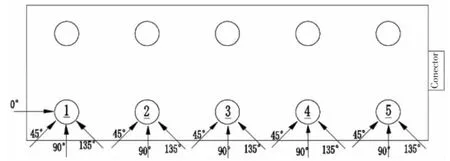
Fig.3 Schematic diagram of the connection type

Fig.4 The impact load time history curve
Ship impact load is selected by referencing impact load formula of Norway bridge load code and modified Worthing formula.By assuming that a bulk carrier with a load of 20 000 T at speed 12 kns hits column,the calculation result with Norway bridge load code is 98.2 MN, and the calculation result with modified Worthing formula is 104.7 MN.In this paper,the ship impact load is selected as 100 MN.The load model is simplified as a rectangular load with a duration of 3 s.The impact load time history curve is shown in Fig.4.
2.2 Environmental load
The environmental load of VLFS is mainly influenced by wind,current and wave.In order to facilitate the study,the velocity of constant wind is chosen as 20 m/s,the velocity of uniform inflow is selected as 0.5 m/s.Wind load and flow load are calculated by NUMECA Fine Marine software.When the flow direction angles are 0°,45°or 90°,the load of wind and flow affected on a single floating body module is shown in Tab.1.The wave is chosen as JONSWAP spectrum,the significant wave height is 4.5 m,spectra peak period is 9.63 s.
2.3 Calculation condition
In this paper,the combined effects of ship impact,wind,wave and current load are considered to study the load characteristics of VLFS.The wind,wave and current are assumed in the same direction as ship impact to obtain the maximum value of the connector load.M1-M5 columns are impacted by ship respectively.The ship impact angles of 0°,45°,90°and 135°are considered to act on M1,and the ship impact angles of 45°,90°and 135°are considered toact on M2-M5.There are 16 kinds of working condition.Hydrodynamic software AQWA is used to simulate various impact conditions and environmental loads.The total computing time is 2 000 s, time step is 0.2 s.The Schematic diagram of hydrodynamic model of VLFS in AQWA is shown in Fig.5.The four connectors are labeled as C1-C4,and the global coordinate system of the whole model and the local coordinate system of the connectors are given,too.

Tab.1 The load of wind and flow in a single floating body module

Fig.5 The Schematic diagram of hydrodynamic model of VLFS in AQWA
3 Calculation results and analysis
3.1 The load of connection point
The statistic value of load on the connector in the three directions when the ship hits the column M1 by four typical angles are given in Fig.6.As shown in figure,when the ship impact angle is 90°,the connector C1 which is near the impact point suffer the largest load in the Y direction.The value of the largest load is 3.49×10⁷N.The maximum loads in the X direction and Z direction appear at the connector C1 with the ship impact angle 0°,which are 7.09×10⁷N and 5.13×10⁷N respectively.As the difference of the ship impact angles,there is a difference in the directions of the maximum stress on the connector.When the ship impact angle is 90°,the load in Y direction reach the maximum.Similarly,the load in X direction is large at the 0°ship impact angle.When the ship impact angle is close to 0°or 180°,the load in X direction becomes larger.The maximum load in Z direction also appears at connector C1 under ship impact angle 0°,which is far greater than the loads of other connectors and the loads under other ship impact angle.


Fig.6 The statistic value of load on the connector in the three directions
The loads statistics of each connector when different columns are hit are shown in Fig.7. As can be seen from Fig.7(b),when the ship hits the column M5 at 90°,the maximum loads of all connectors in the Y direction appear and the largest loads is 4.98×10⁷N.As shown in the Fig.7(a)and Fig.7(c),the load of each connector in X direction and Z direction dose not change with the different impact columns.The reason is that the effect of ship impact on load of each connector in Z or X direction is much less than that of the environment.The loads in X direction and Z direction are mainly produced by environmental load.

Fig.7 The loads statistics of each connector under different working conditions
The load time history curve of each connector in X direction when the ship impacts the column M1 with angle 0°is shown in Fig.8(a).The load time history curve of each connectorin Y direction when the ship impacts the column M5 with angle 90°is shown in Fig.8(b).From the Fig.8,it is obvious that the Fxand Fyof each connector have a clear oscillation in the 1 000 s,the maximum load oscillation amplitude occurs at C1.As shown in Fig.8(c),the time history curve of Fzat each connector has no obvious change,indicating that the effect of ship impact on load of each connector in Z direction is small.

Fig.8 The load time history curve of each connector in three directions
3.2 The bending moment characteristic of hinge point
Each floating body module is connected through a flexible hinged connector,and each connector can be rotated around the Y axis.In this paper,the calculated value of Myis very small,and the maximum amplitude is only 138N·m,So it is unnecessary to consider the influence of bending moment My.From Fig.9(a),it is found that the amplitude of Mxis larger when the ship impact column M1 with angle 90o,and the maximum amplitude appears at the connector C2 which is 1.67×10⁹N·m.The bending moments Mxof two connectors in the middle are larger than that of two connectors at sides.Fig.9(b)shows the statistics value of Mzof each connector when the column M1 is impacted.When the ship impact angle is 90°,the maximum amplitude appears at the connector C2,which is 2.03×10¹⁰N·m.
As shown in Fig.10(a),the impact point is farther away from the connector,the value of the bending moment Mxin each connector is larger.The distance between the impact points is greater,the lever arm is larger,the value of bending moment is larger,which is consistent with common sense.The maximum amplitude of bending moment Mxappears at the connector C2when the ship impact column M1,which is 1.67×10⁹N·m.From Fig.10(b),it is found that the maximum amplitude Mzoccurs at connector C2 when the column M1 is impacted,and the value is 2.03×10¹⁰N·m.

Fig.10 The statistics of bending moments when ship impact angle is 90°
As shown in Fig.11,the maximum value of Mxappears at 1 015 s.Before the impact,the fluctuation of bending moment at the connector caused by the environmental load is small. During the impact,the bending moment has an obvious oscillation,but the oscillation of Mxis weaker than that of Mz.After 1 040 s,the oscillation of Mxbegins to decay.In the 1 000 s of ship impact time,the bending moment Mzhas a larger oscillation,the duration time is 3 s.The bending moment Mzat connector C2 has the greatest oscillation,but the bending moment Mzat connector C4 has the smallest oscillation.

Fig.11 The time history curve of bending moments when the ship hits the column M1 by 90°
4 The influence of environmental load on the load of the connectors
When the ship impact different columns with different angles,the time history curve of load at each connector is shown in Fig.12.The influence of environmental load on the amplitude of Fxat each connector is negligible.The load time history curve of each connector without environmental loads is almost coincide with that under environmental loads.The change trend of time history curve of Fyis influenced by environmental load.The environmental loadhas a certain contribution to the amplitude of Fz,which causes an obvious oscillation on the time history curve of Fz.

Fig.12 The time history curve of load of each connector with or without environmental load

Fig.13 The time history curves of Mxand Mzat connector C2
Due to the hinge type is adopted for the connectors,the value of Mycan be ignored.When the ship impacts the column M1 at 90°,the time history curves of Mxand Mzat connector C2 are shown in Fig.13.It is found that the oscillation of Mxwith environmental load is more severe than the oscillation of Mxwithout environmental load.But the environmental load has small effect on Mz.
5 Conclusions
In this paper,the AQWA software was used to carry out the numerical calculation for the connector loads characteristics of VLFS under ship impact.The ship impact angle,the impact position and the environmental load are considered to calculate and analyze the load of each connector.The conclusions are summarized as follows:
(1)The bending moment along the vertical direction at each connector is the greatest;the ship impact angle and the impact position have a great influence on the connector.The largest bending moment appears when the impact point is far from the connector and the ship impact angle is 90°.
(2)The impact position has a great influence on the load of each connector.The influence of load on connectors in the middle is greater than connectors at sides.
(3)The bending moments along the vertical direction and the transverse loads of different connectors are less affected by the environmental load.But the environmental load has a greater impact on vertical load,longitudinal load and bending moment along the longitudinal direction.
[1]Wang Pu,Yu Lan,Li Runpei,A time sequence analysis method for predicting connector loads in a semi-submersible Very Large Floating Structure[J].Ocean Engineering,2002,20(3):9-13.
[2]Qi Enrong,Liu Chao,Xia Jinsong,Lu Ye,Li Zhiwei,Yue Yalin.Experimental study of functional simulation for flexible connectors of very large floating structure[J].Journal of Ship Mechanics,2015,19(10):1245-1254.
[3]Liu Chao,Qi Enrong,Lu Ye.Dynamic response of connectors of Very Large Floating Structures under shallow draft[J]. Journal of Ship Mechanics,2015,19(10):1245-1254.
[4]Wei Wei,Fu Shixiao,Fei Guo,Liang Yuanhua.The effect of bending stiffness on hydroelastic response ofV LFS[C]//Proceedings of the ASME 33rd International Conference on Ocean,Offshore and Arctic Engineering,San Francisco,June 8-13,2014.California,USA,2014-23710.
[5]Fu Shixiao,Moan Torgeir,Chen Xujun,Cui Weicheng.Hydroelastic analysis of flexible floating interconnected structures [J].Ocean Engineering,2007,34:1516-1531.
[6]Lai Zhimeng,Cheng Xiaoming,Tian Chao,Zhang Kai.Effect of the connector stiffness on the responses of multi-moduled Very Large Floating Structures in waves[C].Proceedings of 13th National Conference on water dynamics and the 26th National Symposium on water dynamics,2014:1484-1494.
[7]Chen Xujun,Moan Torgeir,Fu Shixiao.Extreme response of very large floating structure considering second-order hydroelastic effects in multidirectional irregular waves[J].Journal of Offshore Mechanics and Arctic Engineering,2010,132(4): 1-11.
[8]Gu Jiayang,Wu Jie,Qi Enrong,Guan Yifeng,Yuan Yu-bo.Time domain calculation of connector loads of a Very Large Floating Structure[J].Journal of Marine Science and Application,2015,14(2):183-188.
[9]Wang Cong,Fu Shixiao,Cui Weicheng.Hydroelasticity based fatigue assessment of the connector for a ribbon bridge subjected to a moving load[J].Marine Structures,2008,22(2):246-260.
[10]Yu Lan,Li Runpei,Shu Zhi.Dynamic characteristics of mobile offshore base connectors[J].Journal of Shanghai Jiaotong University,2003,37(8):1159-1163.
[11]Yu Lan,Ding Wei,Li Runpei.Effect of the multiple modules interaction on MOB connector loads[J].Ocean Engineering, 2004,22(1):25-31.
[12]Miguel L P,Gregorio I,Luis C.A review of Very Large Floating Structures(VLFS)for coastal and offshore uses[J].Ocean Engineering,2015,109:677-690.
[13]Riggs H R,Ertekin R C,Mills T R J.Impact of connector stiffness on the response of a multi-module mobile offshore base[C]//Proceedings of the International Offshore and Polar Engineering Conference,May 24-29,1998.Montreal,Can, 1998:200-207.
[14]Riggs H R,Ertekin R C.Response characteristics of serially connected semisubmersibles[J].Journal of Ship Research,1999,43(4):229-240.
[15]Riggs H R,Ertekin R C.Approximate methods for dynamic response of multi-module floating structures[J].Marine Structure,1993,6(2-3):117-141.
[16]Riggs H R,Ertekin R C,Mills T R J.Comparative study of RMFC and FEA models for the wave-induced response of a MOB[J].Marine Structure,2000,13(4-5):217-232.
[17]Watanabe Eiichi,Utsunomiya Tomoaki,Tanigaki Shinkichi.Transient response analysis of a Very Large Floating Structure by Finite Element Method[J].Structural Engineering/Earthquake Engineering,1998,15(2):155-163.
[18]Hisayoshi Endo.The behavior of a VLFS and an airplane during takeoff/landing run in wave condition[J].Marine Structures,2000,13(4-5):477-491.
[19]Kashiwagi M,Higashimachi N.Numerical simulations of transient responses of VLFS during landing and take-off of an airplane[C]//Proceedings of the International symposium of Ocean Space Utilization Technology,January 28-31,2003. Tokyo,Japan,2003:83-97.
碰撞事故时超大型浮体模块连接处荷载特性研究
谷家扬1,朱玥1,谢玉林1,管义锋1,祁恩荣2,陆晔2
(1.江苏科技大学船舶与海洋工程学院,江苏镇江212003;2.中国船舶科学研究中心,江苏无锡214082)
精确评估模块连接处荷载特性对超大型浮体的水动力设计及结构安全性研究具有重要的工程意义。文章以5模块半潜式超大型浮体为研究对象,考虑碰撞荷载和风、浪、流环境荷载的联合作用并采用AQWA软件对超大型浮体模块连接点处的受力特性开展了数值计算。船舶碰撞荷载简化为矩形脉冲,采用定常风、定常流以及JONSWAP波谱,探讨了船舶碰撞角度、撞击位置、环境荷载等因素对模块连接点受力特性的影响。该文的研究成果可为事故荷载作用时超大型浮体连接器结构设计和强度计算提供一定依据。
超大型浮体;连接器;碰撞荷载;环境荷载;运动响应
U661.43
A
谷家扬(1979-),男,博士,江苏科技大学副教授,通讯作者,E-mail:gujayang@126.com;朱玥(1991-),男,江苏科技大学硕士研究生;谢玉林(1994-),男,江苏科技大学硕士研究生;管义锋(1966-),男,江苏科技大学教授;祁恩荣(1965-),男,博士,中国船舶科学研究中心研究员;陆晔(1983-),男,硕士,中国船舶科学研究中心工程师。
U661.43 < class="emphasis_bold">Document code:A
A
10.3969/j.issn.1007-7294.2016.12.007
1007-7294(2016)12-1573-11
Received date:2016-08-29
Foundation item:Supported by National Key Basic Research and Development Program(973)(No.2013CB036104);the National Natural Science Foundation of China(51309123);the Open Foundation of State Key Laboratory of Ocean Engineering(1407)and‘Qing Lan Project’of Colleges and Universities in Jiangsu Province, Academic Program Development of Jiangsu Higher Education Institutions(PAPD),the Collaborative Innovation Center Funded Projects in Jiangsu University(High Technology Ship Category)
Biography:GU Jia-yang(1979-),male,associate professor,corresponding author,E-mail:gujiayang@126.com; QI En-rong(1965-),male,Ph.D.,researcher.
猜你喜欢
昆明理工大学学报·社科版(2022年4期)2022-09-06
华人时刊(2021年15期)2021-11-27
舰船科学技术(2021年12期)2021-03-29
华人时刊(2020年15期)2020-12-14
华人时刊(2020年23期)2020-04-13
华人时刊(2019年21期)2019-05-21
水利与建筑工程学报(2018年4期)2018-08-21
猪业科学(2018年5期)2018-07-17
振动工程学报(2018年3期)2018-07-05
哈尔滨工程大学学报(2017年11期)2017-12-06

- 船舶力学的其它文章
- Effect of Exhaust Angle on Evolutionary and Flow Characteristics of Pressure-equalizing Film on Surface of Underwater Vehicle
- Study on a 3D Time-domain Method to Predict Parametric Rolling of a Ship in Regular Head Seas
- Dynamics and Experiments of a Laboratorial Underwater Glider
- Prediction of Ship-Ship Interaction Forces in Shallow Water Using a High-order Panel Method
- Numerical Evaluation on Dynamic Positioning for Semisubmersible Platform based on Backstepping Control
- Preliminary Evaluation of Maraging Steels on Its Application to Full Ocean Depth Manned Cabin