
A Comparison of Positioning Capabilities between Vessels with Different Thruster Configurations
2016-05-16 02:41,,,
船舶力学 2016年3期
,,,
(State Key Laboratory of Ocean Engineering,Shanghai Jiao Tong University,Shanghai 200240,China)
A Comparison of Positioning Capabilities between Vessels with Different Thruster Configurations
XU Sheng-wen,WANG Xue-feng,WANG Lei,MENG Shuai
(State Key Laboratory of Ocean Engineering,Shanghai Jiao Tong University,Shanghai 200240,China)
Dynamic Positioning Capability(DPCap)analysis is crucially important to the selection of thrusters and their configuration and the preliminary investigation of positioning ability of a newly designed dynamic positioning vessel.In this paper,the effect of the thruster configuration on the positioning capability is investigated,based on a novel synthesized positioning capability criterion.Comparison of positioning capabilities between vessels with different thruster configurations was performed on a semi-submersible.The DPCap results were generated by a newly developed software program.It has been demonstrated that the DPCap results are influenced by the thruster configurations. Based on the synthesized criterion,the comparison of positioning capabilities is highly efficient and accurate.Furthermore,it can be concluded that thruster with a larger distance to the origin of the vessel has more effect on the synthesized positioning capability.
DPCap;thruster configuration;synthesized positioning capability
0 Introduction
A Dynamically Positioned(DP)vessel is by the International Maritime Organization(IMO)and the certifying class societies(DNV,ABS,LR,etc.)defined as a vessel that maintains its position and heading(fixed position or pre-determined track)exclusively by means of active thrusters.Dynamic Positioning System(DPS)has been widely used in offshore engineering over the last five decades.Description of DPSs,including their early history can be found in Fay(1990)[1].
Operation safety is always the first consideration in the design and operation of a new DPS.To be able to plan a safe and efficient operation,it is important to know the window of operation,and the maximum environmental conditions which the particular DP vessel can withstand.During critical operations such as drilling,oil production and offloading,the positioningprecision requirements are high,regardless of the environmental conditions.It is thus important to know the positioning capability of the vessel in order to plan and execute operations in a safe manner,according to Pivano et al(2012)[2].It is necessary to perform a dynamic positioning capability(DPCap)analysis when designing a new DP vessel.
DPCap analysis can help determine the maximum environmental forces that the DP system can counteract for given headings,as IMCA(2000)[3]described.Mostly DPCap analysis investigates the dynamic positioning capability of the vessel from 0°to 360°heading.The environmental forces and moment are statically balanced by thrust forces and moment provided by the thrust system which consists of several kinds of thrusters.The positioning capability is determined by the maximum thrust of the thrusters as well as the thruster configuration.
In the design of a thruster system,there are many factors which are subject to changing (i.e.the number,the types,the maximum thrust and the configuration of the thrusters,etc.). Many efforts can be found in literature focus on the number of the thrusters and their configuration.Mahfouz and El-Tahan(2006)[4]proposed a developed software program as a marine tool in the selection of thrusters,in their configuration,and during preliminary investigation of the positioning ability of a newly designed vessel dynamic positioning system.However,the comparison of vessel’s positioning capability is based on the rough observation of the polar plots,which may cause confusion when these polar plots overlap with each other.A synthesized positioning capability criterion,which can quantify the synthesized positioning capability,is adopted to compare the polar plots.
In this paper,the influence of the thruster configuration on the synthesized positioning capability is focused.The number,types and the maximum thrust of the thrusters are constant. A software program was developed based on the present study in the State Key Laboratory of Ocean Engineering(SKLOE).A DPCap analysis for a semi-submersible was conducted to investigate the synthesized positioning capability of the vessel with different thruster configurations.
This paper is logically constructed in 6 chapters.A basis and flow chart of the DPCap analysis is given in Chap.1,followed by illustration of the synthesized positioning capability criterion in Chap.2.Chap.3 gives a description on the relation of thruster configurations and synthesized positioning capability.Chap.4 performs a comparison of the synthesized capabilities between vessels with different thruster configurations on a semi-submersible.The results and discussion are given in Chap.5.Finally,conclusions will be drawn in Chap.6.
1 DPCap analysis
DPCap analysis can help find the maximum environmental forces that the DP system can counteract for given headings.The accuracy of DPCap analysis is determined by the preciseestimation of the environmental forces as well as the effectiveness of the thrust allocation logic.Estimation of the environmental forces can be based on model tests,hydrodynamic computation and empirical formulas,see Sørensen and Ronxss(2002)[5].Thrust allocation logic can be formulated as an optimization problem,where the objective typically is to minimize the use of control effort(or power)subject to actuator rate and position constraints,power constraints as well as other operational constraint,see Tor A(2004)[6],Fossen and Johansen(2006)[7]. Many methods for optimization are available in literature and quadratic programming method has been demonstrated to be relatively effective and robust,see DE WIT(2009)[8].
Wind,wave and current are assumed coincident in direction when one conducts a DPCap analysis.The forces and moment due to each component are evaluated individually and summed to evaluate the total steady-state environmental forces and moment,as API(1987)[9]described. CFD method can be implemented to evaluate the wind loads,see Gosman(1999)[10],Zhang et al(2010)[11].The second order mean wave loads can be obtained based on quadratic transfer functions,see Newman(1977)and Faltinsen(1990)[12-13].Estimation of the current loads can be found in literature,e.g.Kim et al(2009)[14],Vaz et al(2009)[15],and Leite et al(1998)[16].
The coordinate system is fixed to the vessel body with the origin located at the mean oscillatory position in the average water plane with X axis points towards bow,Y axis points towards port and Z axis points towards upwards.The relative environment angle,α is positive anti-clockwise starting from the stern.Moments are positive anti-clockwise. The coordinate system is illustrated in Fig.1.
A flow chart of DPCap analysis is presented in Fig.2.Given the current heading of the vessel(initially 0),environmental forces and moment are estimated based on the current environmental conditions(initially 0).The environmental forces and moment are balanced by the applied forces and moment,which are provided by the thrust system.Thrust allocation logic determines the optimal solution to generate the applied forces and moment.If the optimal solution exists,the severity of the environmental conditions is increased and the above procedures(Loop1,the small panel in Fig.2)are repeated until an optimal solution no longer exists.The last environmental condition is saved for the current heading.If not all the headings have been completed,move to the next heading and repeat all above procedures(Loop2,the large panel in Fig.2)until all headings are completed.Finally,the polar plot of the vessel is generated based on the heading-dependent environmental conditions.

Fig.1 Coordinate of the vessel

Fig.2 Flow chart of the DPCap analysis
2 Synthesized positioning capability criterion
In DPCap analysis,it may be possible to compare positioning capability results in different cases.In some circumstances,the results can be distinguished by direct observation of the polar plots.However,for overlapping polar plots,there may be confusion in selecting which case has the better positioning capability.Even though the better case is selected according to one’s preference,other factors such as the stability of the positioning capability cannot be accounted for.Thus,a quantified synthesized positioning capability criterion is essential for a direct and accurate comparison.The synthesized positioning capability is determined by the overall mean positioning capability as well as the stability of the vessel heading-dependent capability.
2.1 Overall mean positioning capability
The overall mean positioning capability can be modelled by the expectation of the positioning capabilities.The expectation value can be obtained by integrating the product of the heading-dependent positioning capability and the vessel’s heading probability density function over a given operation heading interval.The operation heading intervalis composed of the headings of the vessel relative to the direction of the environmental conditions. An example of the operation heading interval is given in Fig.3.The overall mean positioningcapability can be represented by

where ψstartand ψendare the counterclockwise headings of the vessel,and satisfy 0≤is the wind velocity limit dependent on the heading of the vesselcan be generated by DPCap analysis and is usually presented in polar format.is a heading probability density function dependent on the heading ψ to the environmental forces.
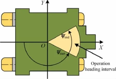
Fig.3 Example of an operation heading interval

where ψiis an arbitrary heading of the vessel,δψ is a small quantity of ψ.The smaller the quantity of δψ,the more precise of the obtained heading probability density function.Ciis the number of counts of the heading during long-term(likely 1 year)observation for a specific frequency(likely to be 1 count per minute).By use of Tab.1,can be obtained by a longterm observation of the vessel’s heading in field tests.

Tab.1 Example of statistics for the heading of the vessel(δψ=5°)
If no field test results can be obtained,the probability of the heading can be assumed to be constant in the given operation heading interval(i.e.Ci=Constant in Eq.(2)).can be represented by

Eq.(3)is a particular case of Eq.(2).
The values of ψstartand ψenddepend on the specific requirements of the vessel’s engineering application.Although the positioning capabilities from 0°to 360°are investigated during DPCap analysis,the only positioning capabilities of concern are the specific headings in the operation heading interval.For a particular vessel operated in a specific maritime zone, the headings of the vessel are usually constrained in a fixed interval.However,the probabilities of the headings in the interval are different.The probability density functionaccounts for the probability of every heading in the given operation heading interval,which makes themodelled overall mean positioning capability more realistic.
2.2 Stability of the capabilities
The stability of the heading-dependent capabilities can be modeled by an item formed by the standard deviation and the expectation of the capabilities in the given operation heading interval.The stability of the capabilities can be represented by:

where σ and μ are the standard deviation and the expectation ofin the operation heading intervalrespectively.The heading probability density functionis also considered in the formulation of σ.
The stability of the capabilities in the given operation heading interval is important for evaluating the synthesized positioning capability of the vessel.With a positioning capability of high stability,the vessel can maintain relatively steady positioning when its heading oscillates, which makes the operation safer.
2.3 Synthesized criterion
The synthesized positioning capability is determined by the overall mean positioning capability as well as the stability of the vessel heading-dependent capability.A possible synthesized criterion can be derived from a product of the overall mean positioning capability and the stability of the capabilities.Eq.(6)gives the formula of the synthesized positioning capability criterion.

where λ is the weight factor of Capstabin the synthesized positioning capability criterion.λ can be increased to give greater weight to the capability stability of the synthesized positioning capability criterion when the vessel requires higher capability stability for safe operation.
The synthesized positioning capability criterion can be used to compare the synthesized positioning capabilities of DP vessels.Actually,for an arbitrary DPCap polar plot,the synthesized capability can be obtained from Eq.(6),which makes the criterion more applicable.For instance,the criterion can be used for comparison of vessels with different thruster configurations or comparison of vessels with different thruster failure modes.Thrust sensitivity analysis takes advantage of the synthesized criterion to quantify the synthesized positioning capability.
3 Thruster configurations
Thruster configuration is essentially important to the thrust allocation logic,which is a core part in the DPCap analysis,as illustrated in Chap.1.
Referring to Tor A(2004)[6],if a marine vessel equipped with m thrusters,the generalizedforce vector τ∈R produced jointly by the thrust system is

where τXis the surge force,τYis the sway force and τNis the yaw moment.The vector u∈R2mcontains the magnitude of the forces produced by each individual thruster in the bow and port direction.Thecolumns of the 3×2m matrix B is given by

The location of the i-th thruster in the horizontal plane isin the adopted coordinate system.
The thruster configuration is formed by the selection of the locationsof the thrusters.A good thruster configuration can assist the thrust system producing sufficient thrust forces and moment simultaneously.However,a poor thruster configuration may help the thrust system apply the surge or sway forces,cannot help providing enough environment moment. Thus,the synthesized positioning capability of the vessel is highly influenced by the thruster configuration.However,the thruster configuration is subject to many constraints related to the deployment of the equipment of the vessel.In this paper,the comparison of the synthesized positioning capability considering different thruster configurations was performed.The thruster configurations were selected based on designs of the real vessels’thrust system.
4 Case studies
Three thruster configurations on the same semi-submersible were taken into consideration for the comparison,as illustrated in Fig.4.The parameters of the semi-submersible is given in Tab.2.It has 8 azimuth thrusters,which have the same particularities.The locations of the thrusters as shown in Fig.4 are tabulated in Tab.3.The maximum thrust of each thruster is 480 kN.Wind and current forces and moment were estimated by a model test conducted in SKLOE.Wave forces and moment were estimated by CFD method.The current velocity was 1 knot in this case,as recommended by IMCA M140.
The interaction between the azimuth thrusters was considered in this paper due to the close distance of the azimuth thrusters.In order to prevent the thruster-thruster interaction from reducing the performance of DP system,forbidden sectors are generally included in thrust allocation algorithms to forbid a thruster entering a sector where a neighboring thruster could be affected by its wake,see Nienhuis(1992)[17].The forbidden sectors are set up as tabulated in Tab.4.
Thruster failure modes were also accounted for in the comparison.Investigated cases are tabulated in Tab.5.Actually,the thrusters are centrosymmetry for every thruster configuration in Fig.4.Thus,there are only two thrusters independent,thruster T1 and thruster T2.

Tab.2 Parameters of the semi-submersible
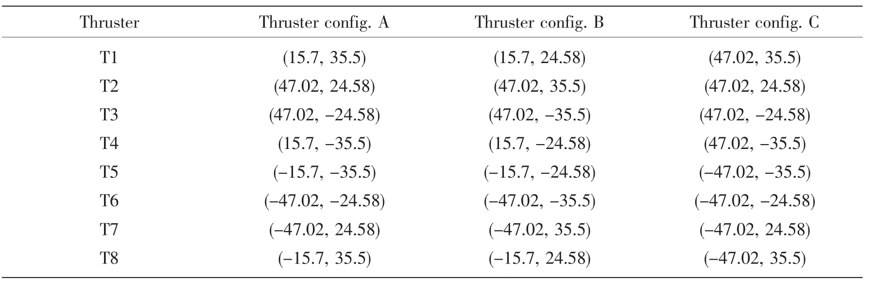
Tab.3 Locations of the thrusters

Fig.4 Different thruster configurations for the same semi-submersible

Tab.4 Forbidden sectors of the thrusters

Tab.5 Investigated cases for failure mode analysis
5 Results and discussions
The results of the investigated cases are presented in Figs.(5)-(9)in a polar format.The polar plots of all cases are almost coincident,especially for case 5 as shown in Fig.9.Most of the polar plots overlap with each other,which causes confusion when one compares their capabilities.The synthesized positioning capability criterion was employed to quantify the synthesized capabilities of the vessel.in all cases,as no probability density function can be obtained.The operation heading interval isthis paper,as no realistic operation heading interval can be obtained.

Fig.5 Polar plots of the dynamic positioning capability of Case 1
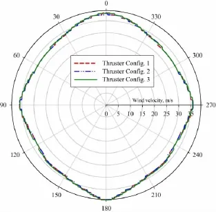
Fig.6 Polar plots of the dynamic positioning capability of Case 2

Fig.7 Polar plots of the dynamic positioning capability of Case 3

Fig.8 Polar plots of the dynamic positioning capability of Case 4
Based on the synthesized positioning capability criterion,the quantified positioning capabilities are obtained,as given in Tab.6.For every thruster configuration given in Fig.4,the synthesized positioning capabilities of the semi-submersible have the following relation:It can be concluded that the more thrusters work,the better the semi’s positioning capabilities are.
From the obtained results,the semisubmersibles with thruster configuration A and thruster configuration B have the similar synthesized positioning capability. Moreover,thruster configuration C has the best positioning capability for all cases except Case 1.When thruster T1 fails,the thrust system cannot supply sufficient moment since thruster T1 of thruster configuration C has a relatively larger distance from the origin of the semi-submersible than that of thruster configurations A and B.This explanation can be confirmed by the results of Case 2,the semi with thruster configuration B has the worst synthesized positioning capability since thruster T2 has the largest distance from the origin of the vessel among all thruster configurations.As a result,the semi with thruster configuration C has the best positioning capability among semis with three thruster configurations in most cases.
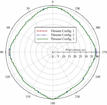
Fig.9 Polar plots of the dynamic positioning capability of Case 5

Tab.6 Quantified positioning capabilities for investigated cases(normalized)

Continue Tab.6
6 Conclusion
In this study,the authors performed a comparison of positioning capabilities between vessels with different thruster configurations.A synthesized positioning capability criterion was employed to quantify the synthesized positioning capability of the vessel.A software program was developed based on the present study.
By use of the synthesized positioning capability criterion,the positioning capabilities of vessels with different thruster configurations can be directly compared with a high efficiency. The investigated cases for a semi-submersible demonstrated the comparison is efficient and accurate.Furthermore,from the obtained results,it can be concluded that thruster with a larger distance to the origin of the vessel has more effect on the synthesized positioning capability.
[1]Fay H.Dynamic positioning systems:Principles,design and applications[Z].Paris:Technip,1990.
[2]Pivano L,Smogeli ØN,Vik B.Dyncap-the next level dynamic DP capability analysis[C].Mar.Cybern.AS,2012.
[3]IMCA.Specification for DP capability plots[K].IMCA M140,2000.
[4]Mahfouz A B,El-Tahan H W.On the use of the capability polar plots program for dynamic positioning systems for marine vessels[J].Ocean Engineering,2006,33:1070-1089.
[5]Sørensen A J,Ronass M.Mathematical modeling of dynamically positioned and thruster-assisted anchored marine vessels [C].In:The Ocean Engineering Handbook,Ferial El-Hawary Ed,2001.
[6]Johansen T A,Fossen T I,Berge S P.Constrained nonlinear control allocation with singularity avoidance using sequential quadratic programming[J].Control Systems Technology,IEEE Transactions,2004,12(1):211-216.
[7]Fossen T I,Johansen T A.A survey of control allocation methods for ships and underwater vehicles[C].In:Mediterranean Conference on Control and Automation,IEEE,2006.
[8]DE WIT C.Optimal thrust allocation methods for dynamic positioning of ships[D].Master thesis.Delft University of Technology,2009.
[9]API.Analysis of spread mooring systems for floating drilling units[S].Recommended practice RP 2P-87,second ed,1987.
[10]Gosman A.Developments in CFD for industrial and environmental applications in wind engineering[J].Journal of Wind Engineering and Industrial Aerodynamics,1999,81:21-39.
[11]Zhang S,Wang L,Yang S Z,Yang H.Numerical evaluation of wind loads on semi-submersible platform by CFD[C].In: ASME 2010 29th International Conference on Ocean,Offshore and Arctic Engineering,2010.
[12]Newman J N.Marine hydrodynamics[M].Cambridge(MA):MIT press,1977.
[13]Faltinsen O M.Sea loads on ships and offshore structures[M].Cambridge(UK):Cambridge University Press,1990.
[14]Kim J S,Hong C B,Lee D Y,Ahn S M.Prediction of current load using computational fluid dynamics[C].In:ASME 2009 28th International Conference on Ocean,Offshore and Arctic Engineering,American Society of Mechanical Engineers,2009.
[15]Vaz G,Waals O J,Ottens H,Fathi F,Le Souef T,Kiu K.Current affairs:Model tests,semi-empirical predictions and CFD computations for current coefficients of semi-submersibles[C].In:ASME 2009 28th International Conference on O-cean,Offshore and Arctic Engineering,2009.
[16]Leite A,Aranha J,Umeda C,De Conti M.Current forces in tankers and bifurcation of equilibrium of turret systems:Hydrodynamic model and experiments[J].Applied Ocean Research,1998,20:145-156.
[17]Nienhuis U.Analysis of thruster effectivity for dynamic positioning and low speed maneuvering[D].Dissertation of Technical University Delft,1992.
不同螺旋桨配置下船舶的定位能力比较
徐胜文,汪学锋,王 磊,孟 帅
(上海交通大学 海洋工程国家重点实验室,上海 200240)
动力定位能力分析对于螺旋桨和螺旋桨配置的选型非常重要,并且可以初步探究一个新设计的动力定位船舶的定位能力。该文中,基于一个新奇的综合动力定位能力标准,探究了螺旋桨的配置对动力定位能力的影响。不同螺旋桨配置下定位能力的比较在一个半潜平台上进行。动力定位能力的结果由一个最新编写的程序计算得到。从得到的结果看,螺旋桨的配置对动力定位能力产生影响。基于综合定位能力标准,定位能力的比较非常高效和准确。而且,可以得到一个结论:与海洋结构物的中心距离越大的螺旋桨对综合定位能力的影响越明显。
动力定位能力;螺旋桨配置;综合定位能力标准
U664.3
:A
徐胜文(1986-),男,上海交通大学博士研究生;
U664.3
:A
10.3969/j.issn.1007-7294.2016.03.004
1007-7294(2016)03-0265-12
汪学锋(1966-),男,上海交通大学教授;
王 磊(1971-),男,上海交通大学副教授;
孟 帅(1985-),男,上海交通大学博士。
Received date:2015-07-24
Foundation item:Supported by the National Key Basic Research Development Plan(973 Plan)Project of China(Grant No.2013CB036103);the National Natural Science Foundation of China(Grant No.51179103)
Biography:XU Sheng-wen(1986-),male,Ph.D.student of Shanghai Jiao Tong University;
WANG Xue-feng(1966-),male,professor/tutor,E-mail:wangxuef@sjtu.edu.cn.
猜你喜欢
电气自动化(2022年2期)2023-01-07
中学生数理化·七年级数学人教版(2021年10期)2021-11-22
航空发动机(2020年3期)2020-07-24
新世纪智能(英语备考)(2019年4期)2019-06-26
中华胸部外科电子杂志(2019年1期)2019-04-02
故事作文·高年级(2017年10期)2017-10-19
兰台世界(2017年10期)2017-06-01
小学阅读指南·低年级版(2016年1期)2016-09-10
中国舰船研究(2014年1期)2014-05-14
客车技术与研究(2014年6期)2014-02-28
- 船舶力学的其它文章
- Numerical Predictions of the Propeller Cavitation behind Ship and Comparison with Experiment
- Establishment of Metamodels for Ship Seakeeping Performance Using an Effective Approximation Modeling Method
- Influence of Added Wave Resistance Calculation Methods on Ship Speed in Seas
- Numerical and Experimental Investigation of the Problem of Diving Difficulty of Autonomous Underwater Vehicle
- Numerical Prediction and Experimental Measurement on Truss Spar Motion and Mooring Tension in Regular Waves
- A Combination Mooring System and Mooring Characteristics Study