
Strategies for CO2 capture from different CO2 emission sources by vacuum swing adsorption technology☆
2016-05-29 02:10JianghuaLingPennyXiaoAugustineNtiamoahDongXuPaulWebleyYuchunZhai
Jianghua Ling ,Penny Xiao ,Augustine Ntiamoah ,Dong Xu ,Paul Webley ,Yuchun Zhai*
1 School of Material and Metallurgy,Northeastern University,Shenyang 110004,China
2 Department of Chemical and Biomolecular Engineering,The University of Melbourne,VIC 3010,Australia
3 Guodian New Energy Technology Research Institute,China Guodian Corporation,Beijing 100000,China
1.Introduction
CO2capture and storage(CCS)occupies an increasingly important place in efforts to mitigate the greenhouse gas emissions that are linked to global warming[1-3].Adsorption as an important separation technology is considered as one of the promising carbon capture methods.Due to the low pressure in flue gases(approximately 0.1 MPa),the vacuum swing adsorption(VSA)method is preferred to pressure swing adsorption(PSA)for CO2capture from these emission sources.
CO2concentration of flue gas varies for different industrial sectors,and hence different VSA cycle configurations may be required.Flue gas from coal- fired power plants contains 10%-15%CO2by volume,and this represents about 50%of all CO2emissions to the atmosphere[4].Other important stationary sources of CO2are cement industries where CO2constitute 14%-33%of the flue gas,and steel production industries with 20%-30%CO2in the flue gas[5].Product gas with>95%CO2(vol/vol)is commonly required for sequestration in order to reduce product compression and transport costs[2].Because fossil-based power plants emit the highest amount of CO2(due to the large size and number of plants in operation),most current research is focused on concentrating CO2from 10%-15%to 95%.Previous studies have shown that very low vacuum pressures(1-5 kPa)are essentially required in order to achieve products of such high CO2concentration at high recovery rates[6-10].Such deeper vacuum levels,if they can be realistic,would require multi-stage vacuum pumps which are expensive to set up and operate.Since the feed gas is only slightly pressurized,the cost of operating the VSA process mainly derives from the energy consumed by vacuum pumps during the desorption stage.Therefore,promising VSA designs for CO2capture must avoid this necessity for very low vacuum desorption,and this is an important research focus.
Two methods can be considered to avoid operating at a deep vacuum pressure:(1)using an adsorbent which has good CO2working capacity,selectivity and also lends itself to easy regeneration,and(2)using multi-stage adsorption units operated in series or using a combination of vacuum pressure and temperature for regeneration.Many adsorbents with promising properties have been developed recently such as Metal Organic Frameworks(MOFs),Zeolitic Imidazolate Frameworks(ZIFs)and amine-modified sorbents,which can present great separation performance in the simulations of VSA cycle[11-13].However,these developments are in a rather very small laboratory scale and it is currently challenging to obtain adequate samples for testing even in laboratory scale experimental rigs.Therefore,VSA process designs for CO2capture still focus on materials that can be synthesized in larger quantities such as zeolites,activated carbon and carbon molecular sieves(CMS).Among those absorbents,zeolite NaX(13X)exhibits relatively higher CO2working capacity and selectivity[14],and hence,most of CO2VSA capture studies used 13X as absorbent[15-18].However,the adsorption capacity of CO2on zeolites is significantly reduced in the presence of water vapor,which is present in flue gas[19,20].
Multiple-layered adsorbent systems have been successfully used,where the first adsorbent layer(e.g.zeolites 3A or activated alumina)preferentially adsorbs H2O in the flue gas and thus,protects the main adsorbent(zeolites 13X)from the negative effects of H2O[21,22].Activated carbon,with both hydrophobic and hydrophilic sites on its surface,can alternatively be used for direct CO2capture(from the water saturated flue gas).H2O is adsorbed through hydrogen bonding to the surface functional groups.This bonding is very weak so that the adsorbed H2O molecules can be removed by reducing its partial pressure[23].Usually,a higher fraction of the water is adsorbed at the bottom part of the bed,leaving less water vapor to pass through the bed,thus,most part of the bed separates CO2and N2.The H2O-vapor and most of SOx,NOxand other impurities can also be removed in flue gas pre-treatment processes before the actual VSA process[7].In this way,the components in the flue gas are reduced to CO2and N2which can be successfully treated using zeolite 13X or activated carbon.This study focused on the separation of CO2from CO2/N2mixture with varying CO2concentration to represent flue gas from different industrial sources.
Generally,adsorption capacity of adsorbents increases with the partial pressure of the adsorbate.Thus,higher separation efficiency can be achieved for the CO2VSA system when the feed gas has higher CO2concentration.At the same desorption pressure,higher recoveries of CO2product can be obtained by reducing adsorption time to ensure that the solute front does not break through the column.With most of the CO2recovered,this product can then be fed to a second VSA unit to further concentrate CO2to near 100%purity without necessarily operating at a very deep vacuum.This multi-stage configuration therefore,promises to be a more practical approach for CO2capture by the VSA technology.
The goal of this study was to design suitable VSA process configurations to upgrade CO2concentration in various feed streams to>95%,ata minimum capture rate of80%.The process designs were focused on using moderate vacuum pressures for desorption,which is a key requirement for large scale application.Zeolite APGIII(upgraded 13X—from UOP)was used as the main adsorbent.Considering the partial hydrophobic characteristic of activated carbon,the VSA performance using GAC(granular activated carbon-coconut shell activated carbon)was also assessed and the results compared with that obtained by using zeolite APGIII.The study is based on simulations using the adsorption simulator MINSA,which was developed by our research group and has been successfully used to predict PSA/VSA cycle performances over a period of two decades[24,25].The system used consists of three adsorption columns,each having dimensions of 20 mm internal diameter and 1090 mm height;and filled with equal amounts of zeolite APG III beads(ID=2 mm,bulk density=773 kg·m-3)and GAC pellets(2.38 mm × 1.00 mm,bulk density=500 kg·m-3).Adiabatic system was assumed.A feed gas temperature of 40°C was considered,assuming this to be the exit temperature of the flue gas after pre-treatment processes.The performance of single VSA cycles with and without a product purge step,and 2-stage VSA process configurations have been investigated.
2.Experimental
2.1.Adsorption characteristics of adsorbents

Fig.1.Isotherms of CO2 and N2 on APGIII(a)and GAC(b).(Symbols—experimental data;lines— fits to Dual-site Langmuir model).
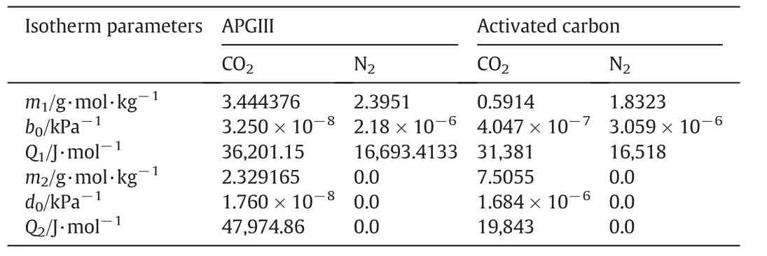
Table 1 Dual-site Langmuir adsorption equilibrium parameters of CO2 and N2 on APGIII and GAC
Zeolite APGIII is a new molecular sieve from UOP,which has higher CO2adsorption capacity compared with their earlier generation molecular sieve 13X APG[26].The isotherms of CO2and N2were measured with a volumetric adsorption analyzer(Micromeritics,ASAP 2010).Fig.1 presents the plots of isotherm data for APGIII,while Table 1 lists the parameters of the Dual-site Langmuir model for both APGIII and GAC.The model equations are presented in Eqs.(1)and(2).
From the isotherm plots(Fig.1),CO2adsorption amount on APGIII(at any given temperature)is much higher than N2.This shows that the adsorbent is suitable for CO2separation from N2.At 40°C(considered here to be the feed gas temperature)and CO2partial pressure of 15 kPa,amount of CO2adsorbed is 3.4 mol·kg-1.At the same temperature,adsorption amounts at other CO2partial pressures are 4.1 mol·kg-1at 30 kPa,4.32 mol·kg-1at 40 kPa and 4.77 mol·kg-1at 70 kPa,showing that adsorption capacity increases with adsorbate partial pressure.GAC curves show the similar trend as APGIII.Because adsorption is exothermic and the bed is assumed to operate under adiabatic conditions,temperature in the bed will rise and fall during adsorption and desorption processes.Therefore,the real working capacity will be lower than those calculated from the isotherm data.The calculation of the actual selectivity of CO2over N2will also be more complex for the same reasons.

where n is the adsorbed amount(mol·kg-1),m1and m2represent the saturated adsorbed loading corresponding to sites Iand II(g·mol·kg-1)respectively,p represents the equilibrium partial pressure of CO2(kPa).b0and d0are the coefficients(kPa-1),Q1and Q2are the adsorption heats(J·mol-1),R is the universal gas constant(8.3145 J·mol-1·K-1)and T is the temperature(K).
2.2.Cycle design and simulation
Two VSA cycles based on three adsorbent beds(3-bed/12-step and 3-bed/9-step cycles)were designed to evaluate the performance of the VSA technique for CO2capture from different feed streams.The sequence of cycle steps is depicted schematically in Fig.2 for the 12-step cycle.Each of the three beds undergoes all the cycle steps alternately.The 9-step cycle is obtained from Fig.2 by withdrawing steps 4(product purge)and,8 and 12(idle steps).An inhouse numerical simulator MINSA,which was built on the basis of mass and energy balances applied varieties of adsorption isotherm models,kinetic models and heat transfer models as described earlier was used to simulate the cycles.The set of assumptions,models and parameters were explained in detail previous work of our group[9,26].And the boundary conditions are set following the operating conditions,listed in Table 2.
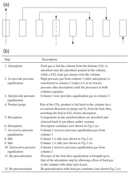
Fig.2.VSA cycle design.
3.Results and Discussion
3.1.Performance of 3-bed/9-step cycle for a feed gas containing 15%CO2:Effects of vacuum pressure
3.1.1.Using APGIII as adsorbent
Productpurity increases when vacuum pressure is lowered[Fig.3(a)].Product purity of 95%and recovery of 90%CO2were achieved when vacuum pressure atthe end ofdesorption step reached 1 kPa.This reduced to 91%purity and 80%recovery at 3 kPa;and 85%purity with recovery of 61%at 5 kPa.For the cycle considered here,we found that CO2purity was limited even when CO2recovery was heavily sacrificed(by extending adsorption time until complete CO2breakthrough occurred).The maximum CO2product purity was found to be approximately 91%at desorption pressure of 3 kPa,45%at 15 kPa and 38%at 20 kPa.On the other hand,ifa target CO2recovery of90%is required,CO2productpurity is 52%atthe vacuumpressure of10 kPa,42.5%at15 kPa and 38%at20 kPa.Thus,there is a trade-offbetween purity and recovery.Fig.3(b)also shows that more energy is consumed as product purity increases with the level of vacuum pressure.Power is consumed during feeding and desorption steps for this nine-step cycle.About 496.8 kJ·(kg CO2)-1power was consumed in order to obtain a product of 95%CO2and recovery of 90%from a feed containing 15%CO2.Since the feed gas is only lightly compressed(to 0.11 MPa)significant part of the power consumption is due to the vacuum pump,which was found to be seven times.
3.1.2.Using GAC as adsorbent
Trends in performances using GAC[Fig.4(a)]are similarto those observed by using APGIII as adsorbent[see Fig.3(a)].By fixing CO2recovery,product purity increases with decreasing vacuum pressure.However,because CO2adsorption capacity and selectivity on zeolite APGIII are much higher than those on GAC(Fig.1),the performance of VSA cycles using zeolite APGIII was better than that using GAC as adsorbent.As noted earlier,with this cycle(without a product purge),it is challenging to achieve CO2product purity of 95%and recovery of 90%with GAC even when a very low vacuum pressure of 1 kPa is used.At a fixed recovery of 90%,maximum purities obtained with GAC were 47.5%and 40%at vacuum pressures of 10 kPa and 15 kPa respectively.
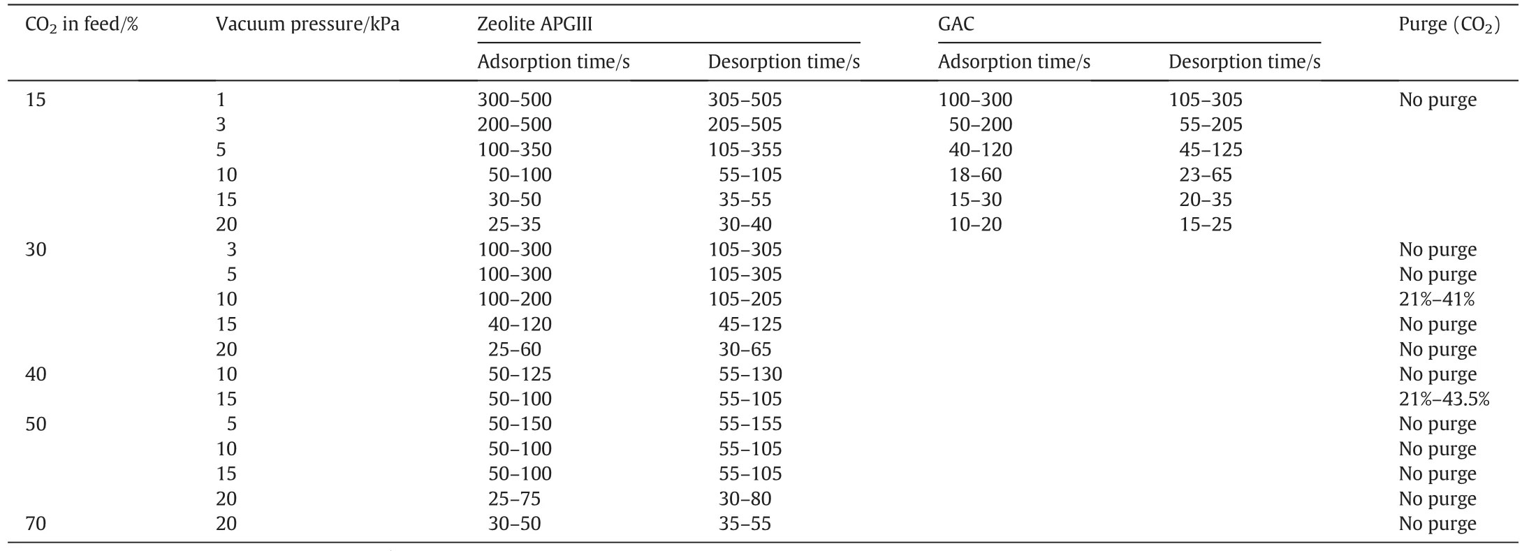
Table 2 Operating conditions used in simulations
3.2.Performance of 3-bed/9-step cycle using APGIII as adsorbent:Effects of feed CO2 concentration
As mentioned earlier,CO2concentration in feed gas differs with differentemission sources.Here,simulations were performed on the same process cycle(3-bed/9-step cycle)by varying inlet feed CO2concentration from 30%-70%.

Fig.3.VSA performance for feed gas of 15%CO2 at various vacuum levels using zeolite APGIII as adsorbent(a)purity and recovery of CO2 products(T=40°C;P=0.11 MPa);(b)power consumption via the performance at vacuum level of 1 kPa.
Product purities and recoveries for the different feed concentrations are presented in Fig.5(a-d).It can be seen that high CO2product purity and recovery can be obtained withouta productpurge,from a feed with higher CO2concentration,even atmoderate vacuumpressures.Vacuum levelof 20 kPa could upgrade CO2concentration from 70%in the feed to 97.5%at a recovery of 99%.Using a vacuum level of 15 kPa also resulted in 95%CO2product purity and 90%recovery from a feed gas with CO2concentration of 50%;while 95%CO2purity with 85%recovery was achieved at the vacuum level of 20 kPa for the same feed composition.For a feed gas containing 40%CO2,10 kPa vacuum pressure would be required in order to obtain 95%CO2product purity with 91%recovery.A vacuum level of 15 kPa could also produce a product with CO2purity of 95%from a feed gas containing 40%CO2concentration.For the feed gas containing less than 30%CO2,low vacuum(less than 5 kPa)would be required if the purity and recovery targets were set at>95%and>90%respectively.However,10 kPa produced acceptable performance of92.3%purity with the recovery of75%from the feed gaswith 30%CO2.
The increase in product purity at even moderate vacuum pressure is due to increasing working capacity with adsorbate partial pressure in the feed.Moreover,even though CO2is strongly adsorbed on zeolite 13X(APGIII),small amount of N2is also adsorbed or filled in the void spaces of the bed;which decreases with increasing CO2concentration in the feed.Thus,both purity and recovery increase with increasing feed CO2concentration and decreasing vacuum pressure.
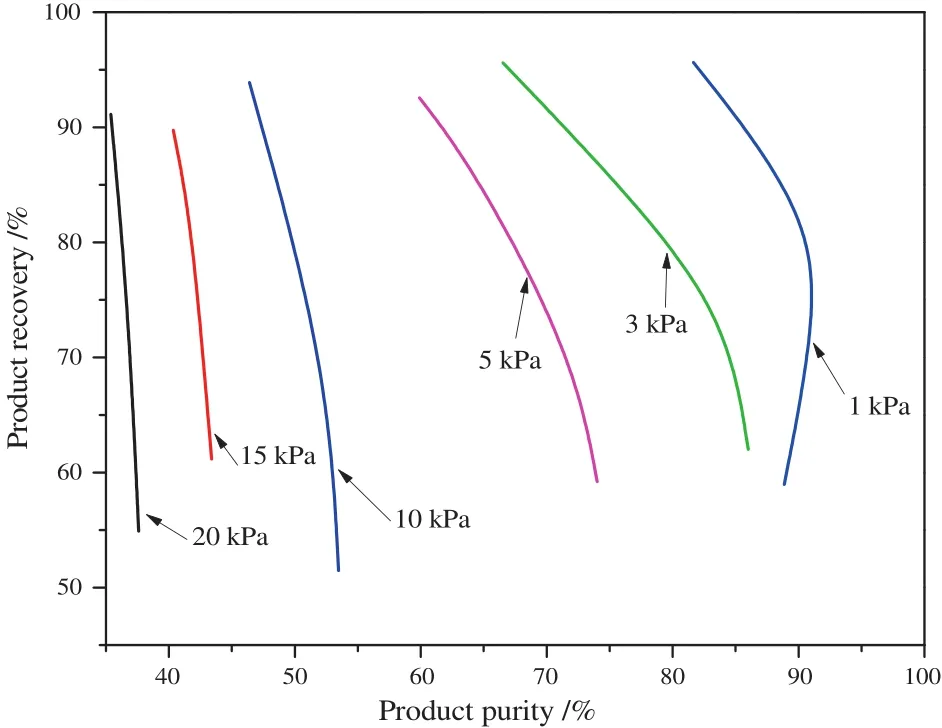
Fig.4.VSA performance for feed gas of 15%CO2 at various vacuum levels using GAC as adsorbent.
Generally,CO2adsorption amount on the bed keeps increasing until breakthrough(but recovery decreases as adsorption time increases due to loss of CO2in the effluent).Thus,more CO2can also be desorbed during desorption steps until the value theoretically reaches the maximum at CO2breakthrough point.By pressure equalization,gas containing some amounts of CO2is transferred from a bed at a higher pressure to another at a lower pressure.This reduces the theoretical amount of CO2adsorbed on the bed that provides the equalization gas as its total pressure is lowered.There are also pressure drop and kinetic issues as the feed gas passes through the packed bed.Therefore,the real CO2desorption amount(per bed)would be lower than the working capacity(WC)calculated from the isotherm data using Eq.(3).

where nadsis the adsorption amount in the bed at higher feed CO2partial pressure,and ndesis the adsorption amount in the bed at the lower CO2partial pressure during desorption.(Equilibrium adsorption is assumed in this analysis).
As an example,we show in Table 3,the amounts of CO2desorbed,the maximum purities obtained and calculated CO2working capacities from the isotherm data(Fig.1)at different desorption pressures for the feed gas with CO2concentration of 30%.
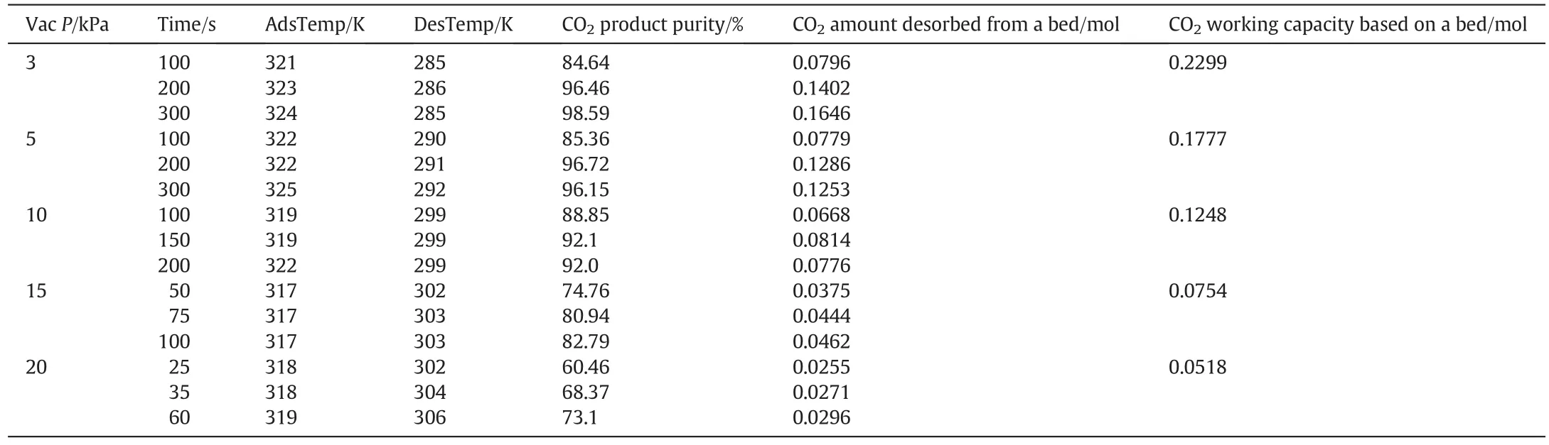
Table 3 CO2 purity and amount desorbed under various run conditions:Actual experimental results and estimates from isotherm data
3.3.Performance of 3-bed/12-step cycle using APGIII as adsorbent(introducing product purge)
The product purge applied prior to desorption,enriches the bed in CO2,which then leads to higher product purity[9,27,28].The effect of CO2product purge(see 3-bed/12-step cycle—Fig.2 and Table 2)on product purity is shown in Fig.6.
As shown in Fig.6(a),41%ofthe collected productduring desorption(in a cycle)was used to purge the bed before evacuation at 10 kPa in order to raise product purity from 88.85%(9-step cycle)to 95.17%(12-step cycle),with CO2recovery dropping from 88.45%to 79.72%for a feed gas with 30%CO2.Power consumption also increased from 235 kJ·(kg CO2)-1to 342.14 kJ·(kg CO2)-1.Lesser amount of purge gas(21%of product)was required to raise CO2purity from 92.10%to 95%,with CO2recovery decreasing from 73.68%to 66.30%.For the feed gas containing 40%CO2[Fig.6(b)],43.5%CO2productpurge was required to raise productpurity from 85.85%to 95.23%with power increasing from 184.90 kJ·(kg CO2)-1to 287.71 kJ·(kg CO2)-1;21%of product was also used as purge gas to raise product purity from 91.8%to 95.25%with extra power of 41.78 kJ·(kg CO2)-1.It is possible to raise CO2product purity by 10%by including a product purge step in the cycle but at the expense of power consumption.The purge front can break through the column,and if not properly controlled,the product purge step can lead to lower recoveries due to the loss of product in the effluent.
3.4.Performance of 2-stage VSA units for feed gases with different CO2 concentrations
As discussed above,desorption at near complete vacuum is required in order to reach higher product purities in cases where the feed contains less CO2concentration such as power plant flue gas.As noted earlier,such deeper vacuum pressures are not practical due to the large vacuum pump size and large pipelines that would be required.In addition,deep vacuum desorption also results in a large temperature swing between adsorption and desorption which negatively affects CO2working capacity.For such cases,we proposed a 2-stage VSA process as a more practical approach to avoid operating at a very low vacuum pressure.
3.4.1.CaseI:Simulationofa2-stageVSAprocessforafeedgaswith15%CO2 concentration
The proposed 2-stage VSA process for the feed gas containing 15%or lower CO2concentration is shown schematically in Fig.7.The process design is tailored to achieve the highest obtainable recovery in the first VSA unit using simple process cycles(by manipulating the cycle time).The entire productstream is then sentto the second stage process as feed.

Fig.6.VSA performance for CO2 capture after introducing a product purge step(a)CO2 concentration of 30%in feed gas(T=40°C;P H=0.11 MPa;P L=0.01 MPa);(b)CO2 concentration of 40%in feed gas(T=40°C;P H=0.11 MPa;P L=0.1 MPa).

Fig.7.Schematic of 2-stage VSA process for CO2 separation.

Table 4(a)Performance of a 2-stage VSA process using APGIII as adsorbent for feed gas containing 15%CO2

Table 4(b)Performance ofa two-stage VSAprocess using GAC as adsorbentin the firststage and APGI II in the second stage for CO2 capture from feed gas containing 15%CO2
Predicted CO2purity,recovery and totalspecific powerconsumption in the two-stage VSA process are presented in Table 4(a)and 4(b)for APGIII and GAC respectively.For example,for the first stage process,we selected the performance of50%CO2productpurity,92.8%recovery and 382 kJ·(kg CO2)-1specific power at a vacuum level of 10 kPa for APGIII(Fig.3a).The second stage process with feed containing 50%CO2produced a product of 95.3%CO2purity and specific power of 211 kJ·(kg CO2)-1at 10 kPa(Fig.5c).After configuration, final purity of 95.3%CO2and recovery of 98.2%were obtained,with overall specific power consumption of 551 kJ·(kg CO2)-1.These final results were estimated using Eqs.(4)and(5).
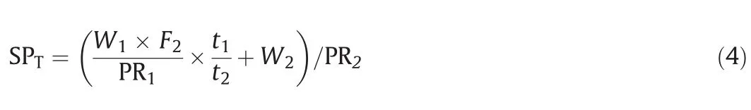
where SPTis the total specific power;W1,W2(PowerCom,kJ)are the power consumption for one cycle in stage 1 and 2;F2is the feed flowrate in one cycle in stage 2;PR1(kg)is the CO2rich gas in one cycle from stage 1;PR2(kg)is the final CO2product from stage 2;and t1and t2are the cycle times in stages 1 and 2 respectively.

where RTis the total recovery;R1is CO2product recovery in stage 1 and R2is CO2product recovery in stage 2.
党的十八大以来,以习近平同志为核心的党中央坚持把解决好“三农”问题作为全党工作的重中之重,不断加大强农惠农富农政策力度,持续推进农业现代化和城乡融合,取得了历史性成就。
From Table 4(a),the total specific power consumption of the 2-stage process operating at 10 kPa vacuum pressure(551 kJ·(kg CO2)-1)was less than that in a one-stage process at operating at 1 kPa(Fig.3b)(for similar product purity and recovery).At vacuum pressure of 15 kPa,CO2product with higher purity could also be obtained,but specific energy consumption would be slightly higher[573 kJ·(kg CO2)-1]due to the relatively lower recovery.If GAC is used in the first VSA process with the same cycle,specific power consumption is higher as shown in Table 4(b).However,it is still worth considering this arrangement because of the lower cost and water tolerance of activated carbon.
3.4.2.Case II:2-stage VSA process for feed gas with CO2concentration between 30%and 40%
As shown in Fig.6(a)(30%CO2in feed gas),purging the bed with 41%of the collected product produced 95%product purity with a recovery of 80%at10 kPa.The energy consumption was 342.1 kJ·(kg CO2)-1.If a higher recovery is required,a two-stage process can be run at15 kPa and 20 kPa.The results for such a process are listed in Table 5.From stage I,CO2purity was upgraded to 70%with recovery 95.7%at vacuum pressure of 15 kPa;or to a purity of 60.5%with recovery of 98.75%using 20 kPa vacuum pressure.When such CO2-rich gas streamwas fed to the second VSA unit,higher than 95%purity and very high recovery could be achieved from both vacuum pressures of 15 kPa and 20 kPa.

Table 5 Performance ofa two-stage VSAprocess for CO2 capture from feed gas containing 30%CO2
3.4.3.Case III:2-stage VSA process for feed gas with CO2 concentration≥40%
For feed gases with CO2concentration≥40%,a single stage VSA process can easily yield very high product purity and recovery.The performances for treating feed gases with CO2concentrations of 40%and 50%are listed in Table 6.Power consumption decreased with increasing feed CO2concentration due to the moderate vacuumpressures used in those cases to achieve similar high product purity and recovery.
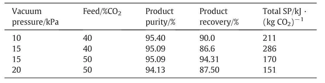
Table 6 Performance of a two-stage VSA process for CO2 capture from feed gas containing 40%and 50%CO2
Table 7 presents summarized results of some reported VSA studies in order to compare them with the main results of the current study.The 2-stage process emphasized in this study has been considered by some previous researchers as well.Cho et al.[29]reported a two-stage VPSA process with two beds per stage designed for CO2capture from power plant flue gas.The first stage unit was used to enrich the CO2from 10%to 63.2%,which was further enriched to 99%in the second stage process.The high purge flow rate in the firststage and low CO2recovery in the second stage process(45%)contributed much to the higher specific energy consumption as indicated in Table 7.Lu et al.[30]also simulated a two-stage VPSA for CO2capture including a three-column front VPSA unit where CO2purity was increased to 70%and a tail two-column VPSA unit which further raised the purity to 96%.The absence of a product purge step was keyed in the relatively lower energy consumption realized.The conditions and cycles are not identical,nevertheless,it can be seen that,in all cases,the multi-stage process easily achieves high separation efficiency in terms of product purity and recovery.
Power consumption is often estimated using the adiabatic power law with constant pump/compressor efficiency.However,a recent study by Farooq and co-workers[31]found that the measured power consumption of VSA processing corresponded to theoretical valuesbased on 30%pump efficiency.It must be noted that pump efficiency,η,may decrease with deeper vacuum level because volumetric velocity decreases nonlinearly as deeper vacuum levels are reached.When the system is operated at moderate vacuum pressure,the error between experimental result and calculation value may be less.

Table 7 Specific energy consumption of some VPSA/TSA cycles
4.Conclusions
CO2capture requirements emphasize high product purity and recovery and low energy consumption.For the VSA capture process,we found that the vacuum pressure level used is the key element for achieving these performances and the feed CO2concentration determines the requirement for vacuum desorption level and whether a single stage or multiple stages of VSA units would be required for the separation.
The vacuum pressure required in a single-stage VSA process in order to produce product with high CO2purity and recovery decreases towards zero vacuum with decreasing feed CO2concentration.Until new materials with superior properties become commercially available,multi-stage VSA process may be required to treatfeed streams with low CO2concentration such as in power plant flue gas in order to avoid operating at a very low vacuum pressure,which would have more engineering issues on a large scale.For a feed gas with CO2concentration higher than 30%,moderate vacuum pressure o achieved the required high separation performance.
As indicated in this study and many others(Table 7),CO2purities and recoveries as well as specific power consumption compared to those from the single stage at deep vacuum desorption have been obtained with two-stage VSA units based on basic cycle steps and operating at moderate vacuum pressures.However,installing two or more stages of adsorption units may lead to an increase in capital cost and this must be assessed in a future study.
References
[1]K.S.Lackner,A.H.A.Park,B.G.Miller,Eliminating CO2emissions from coal- fired power plants,Academic Press,Burlington,USA,2010.
[2]S.A.Rackley,Carbon capture and storage,Elsevier Inc.,Burlington,USA,2010.
[3]Z.Zhang,H.Ruan,Y.Zhou,W.Su,Y.Sun,L.Zhou,A research note on the adsorption of CO2and N2,Chin.J.Chem.Eng.19(2011)733-737.
[4]IEA,CO2emissions from fuel combustion—Highlights,International Energy Agency,Paris,France,2014.
[5]B.Metz,O.Davidson,H.D.Coninck,M.Loos,L.Meyer,IPCC special report on carbon dioxide capture and storage,Cambridge University Press,New York,USA,2005.
[6]M.Ishibashi,H.Ota,N.Akutsu,S.Umeda,M.Tajika,J.Izumi,A.Yasutake,T.Kabata,Y.Kageyama,Technology for removing carbon dioxide from power plant flue gas by the physical adsorption method,Energy Convers.Manag.37(1996)929-933.
[7]R.V.Siriwardane,M.-S.Shen,E.P.Fisher,J.A.Poston,Adsorption of CO2on molecular sieves and activated carbon,Energy Fuels 15(2001)279-284.
[8]J.Zhang,P.A.Webley,P.Xiao,Effect of process parameters on power requirements of vacuum swing adsorption technology for CO2capture from flue gas,Energy Convers.Manag.49(2008)346-356.
[9]J.Zhang,P.A.Webley,Cycle development and design for CO2capture from flue gas by vacuum swing adsorption,Environ.Sci.Technol.42(2008)563-569.
[10]R.Haghpanah,R.Nilam,A.Rajendran,S.Farooq,I.A.Karimi,Cycle synthesis and optimization of a VSA process for postcombustion CO2capture,AICHE J.59(2013)4735-4748.
[11]Q.Wang,J.Luo,Z.Zhong,et al.,CO2capture by solid adsorbents and their applications:Current status and new trends,Energy Environ.Sci.4(2011)42.
[12]A.Nalaparaju,M.Khurana,S.Farooq,et al.,CO2capture in cation-exchanged metalorganic frameworks:Holistic modeling from molecular simulation to process optimization,Chem.Eng.Sci.124(2015)70-78.
[13]B.J.Maring,P.A.Webley,A new simplified pressure/vacuum swing adsorption model for rapid adsorbent screening for CO2capture applications,Int.J.Greenhouse Gas Control 15(2013)16-31.
[14]P.J.E.Harlick,F.H.Tezel,An experimental adsorbentscreening study for CO2removal from N2,Microporous Mesoporous Mater.76(2004)71-79.
[15]K.T.Chue,J.N.Kim,Y.J.Yoo,S.H.Cho,R.T.Yang,Comparison of activated carbon and zeolite 13X for CO2recovery from flue gas by pressure swing adsorption,Ind.Eng.Chem.Res.34(1995)591-598.
[16]D.Ko,R.Siriwardane,L.T.Biegler,Optimization of a pressure-swing adsorption process using zeolite 13X for CO2sequestration,Ind.Eng.Chem.Res.42(2003)339-348.
[17]P.Xiao,J.Zhang,P.Webley,G.Li,R.Singh,R.Todd,Capture of CO2from flue gas streams with zeolite 13X by vacuum-pressure swing adsorption,Adsorption 14(2008)575-582.
[18]D.P.Bezerra,R.S.Oliveira,R.S.Vieira,C.L.Cavalcante,D.C.S.Azevedo,Adsorption of CO2on nitrogen-enriched activated carbon and zeolite 13X,Adsorption 17(2011)235-246.
[19]A.Sayari,Y.Belmabkhout,R.Serna-Guerrero,Flue gas treatment via CO2adsorption,Chem.Eng.J.171(2011)760-774.
[20]D.Xu,P.Xiao,G.Li,J.Zhang,P.Webley,Y.Zhai,CO2capture by vacuum swing adsorption using F200 and sorbead WS as protective pre-layers,Chin.J.Chem.Eng.20(2012)849-855.
[21]J.Zhang,P.Xiao,G.Li,P.A.Webley,Effect of flue gas impurities on CO2capture performance from flue gas at coal- fired power stations by vacuum swing adsorption,Energy Procedia 1(2009)1115-1122.
[22]G.Li,P.Xiao,J.Zhang,P.A.Webley,D.Xu,The role of water on postcombustion CO2capture by vacuum swing adsorption:Bed layering and purge to feed ratio,AICHE J.60(2014)673-689.
[23]J.Rodríguez-Mirasol,J.Bedia,T.Cordero,J.J.Rodríguez,In fluence of water vapor on the adsorption of VOCs on lignin-based activated carbons,Sep.Sci.Technol.40(2005)3113-3135.
[24]P.A.Webley,J.He,Fast solution-adaptive finite volume method for PSA-VSA cycle simulation-1 single step simulation,Comput.Chem.Eng.23(2000)1701-1712.
[25]P.A.Webley,J.M.He,Fast solution-adaptive finite volume method for PSA/VSA cycle simulation;1 single step simulation,Comput.Chem.Eng.23(2000)3217-3224.
[26]J.H.Ling,A.Ntiamoah,P.Xiao,P.A.Webley,Y.C.Zhai,Effects of feed gas concentration,temperature and process parameters on vacuum swing adsorption performance for CO2capture,Chem.Eng.J.265(2015)47-57.
[27]S.P.Reynolds,A.Mehrotra,A.D.Ebner,J.A.Ritter,Heavy reflux PSA cycles for CO2recovery from flue gas:Part I.Performance evaluation,Adsorption 14(2008)399-413.
[28]E.S.Kikkinides,R.T.Yang,S.H.Cho,Concentration and recovery of CO2from flue gas by pressure swing adsorption,Ind.Eng.Chem.Res.32(1993)2714-2720.
[29]S.H.Cho,H.P.Jong,T.B.Hee,S.H.Sang,N.K.Jong,A 2-stage PSA process for the recovery of CO2from flue gas and its power consumption,Stud.Surf.Sci.Catal.153(2004)405-410.
[30]L.Wang,Z.Liu,P.Li,J.Wang,J.Yu,CO2capture from flue gas by two successive VPSA units using 13XAPG,Adsorption 18(2012)445-459.
[31]S.Krishnamurthy,V.R.Rao,S.Guntuka,et al.,CO2capture from dry flue gas by vacuum swing adsorption:A pilot plant study,AIChE J.60(2014)1830-1842.
[32]A.Agarwal,L.T.Biegler,S.E.Zitney,A superstructure-based optimal synthesis of PSA cycles for post-combustion CO2capture,AIChE J.56(2009)1813-1828.
[33]J.Merel,M.Clausse,F.Meunier,Experimental investigation on CO2post-combustion capture by indirect thermal swing adsorption using 13X and 5A zeolites,Ind.Eng.Chem.Res.47(2008)209-215.
[34]Z.Liu,L.Wang,X.M.Kong,P.Li,J.G.Yu,A.E.Rodrigues,Onsite CO2capture from flue gas by an adsorption process in a coal- fired power plant,Ind.Eng.Chem.Res.51(2012)7355-7363.
[35]Z.Liu,C.A.Grande,P.Li,J.G.Yu,A.E.Rodrigues,Multi-bed vacuum pressure swing adsorption for carbon dioxide capture from flue gas,Sep.Purif.Technol.81(2011)307-317.
[36]C.Z.Shen,Z.Liu,P.Li,J.G.Yu,Two-stage VPSA process for CO2capture from flue gas using activated carbon beads,Ind.Eng.Chem.Res.51(2012)5011-5021.
猜你喜欢
中共云南省委党校学报(2022年1期)2022-04-26
乡村科技(2021年20期)2021-12-14
今日农业(2021年2期)2021-11-27
今日农业(2021年14期)2021-11-25
今日农业(2021年14期)2021-11-25
今日农业(2021年14期)2021-10-14
今日农业(2021年15期)2021-10-14
今日农业(2021年13期)2021-08-14
金桥(2021年4期)2021-05-21
今日农业(2019年15期)2019-09-03
 Chinese Journal of Chemical Engineering2016年4期
- Chinese Journal of Chemical Engineering的其它文章
- Evaluation of substrates for zinc negative electrode in acid PbO2-Zn single flow batteries☆
- Enhanced production of glycyrrhetic acid 3-O-mono-β-D-glucuronide by fed-batch fermentation using pH and dissolved oxygen as feedback parameters☆
- Production of succinic acid in basket and mobile bed bioreactors—Comparative analysis of substrate mass transfer aspects☆
- Production of carbonaceous material from avocado peel for its application as alternative adsorbent for dyes removal
- Continuous production of biodiesel from cottonseed oil and methanol using a column reactor packed with calcined sodium silicate base catalyst☆
- Prediction of pyrolysis kinetic parameters from biomass constituents based on simplex-lattice mixture design☆