
Experimental Analysis of A Cooling System for Wind-Driven Generator Stator
2016-09-14 01:16QianXiaohuiJiangYanlongChengDanfengLiuJuan
Qian Xiaohui,Jiang Yanlong*,Cheng Danfeng,Liu Juan
1.College of Aerospace Engineering,Nanjing University of Aeronautics &Astronautics,Nanjing 210016,P.R.China;2.Shanghai Aircraft Design &Research Institute,Commercial Aircraft Corporation of China,Ltd,Shanghai 200232,P.R.China(Received 2July 2014;revised 25June 2015;accepted 1August 2015)
Experimental Analysis of A Cooling System for Wind-Driven Generator Stator
Qian Xiaohui1,Jiang Yanlong1*,Cheng Danfeng1,Liu Juan2
1.College of Aerospace Engineering,Nanjing University of Aeronautics &Astronautics,Nanjing 210016,P.R.China;
2.Shanghai Aircraft Design &Research Institute,Commercial Aircraft Corporation of China,Ltd,
Shanghai 200232,P.R.China
(Received 2July 2014;revised 25June 2015;accepted 1August 2015)
A novel cooling system with cooling channels is proposed for the stator of 3MW wind-driven generator. An experimental platform is built to investigate the performance of the cooling system with different loads.At 30%,50%or 80%generator loads,the temperatures meet the design requirement.However,it is a little over the requirement at 100%load,duo to experimental errors and some unknown thermal resistances.In the test at 100% load,the developing trends of the parameters of these two generators are similar and only minor differences occurs when they reach steady state our work can be benefit for the design and improvement of MW wind-driven generator cooling solutions.
wind-driven generator;stator cooling channels;cooling method;experimental study
0 Introduction
Wind-driven generator is an outstanding clean technique in current energy-crisis-era,thanks to its sustainability,fast-development,and cost-effectiveness.Therefore,the wind-driven power grid is expanding and urgently calls for larger capacity generators.Unfortunately,high temperature problems in large capacity generator remain unsolved and hinder the development of the clean technique[1-4].High temperature causes more loss and heat and therefore hurts generator′s efficiency and service life[5-6].Previous researches demonstrated that high temperatures mainly occur in iron core and winding,and the temperature in the latter is higher than that in the former.Therefore,properly designed stator cooling channels are crucial to highly efficient,reliable and safe operations.Currently,most studies focus on numerical simulations for temperature rise of hydro and turbo generator stators.Some other scholars optimized the structure of ventilating and cooling system[7-8].However,few researchers have looked into the cooling performance of the wind-driven generator stator,let alone experimental analysis.
Therefore,we propose a conceptual design of cooling channels for 3MW wind-driven generator stator,and establish a platform to validate it.The cooling performance is investigated at different generator loads.The work will provide a reference for the design and the improvement of the cooling operation of MW wind-driven generator.
1 Wind-Driven Generator Cooling Channel Design
Air cooling method is widely used for winddriven generators within China.When generator capacity is larger,air cooling cannot dissipate enough heat.Liquid cooling mediums can also be used to cool generators,but it usually brings about complicated structures,so it is impossible toset too much liquid cooling channels.Therefore,we combine circulated liquid cooling with air blast cooling to improve generator cooling performance.60%ethylene glycol solution is used as the cooling medium to avoid frost in winter.
The cooling channels are designed as shown in Fig.1.There are air channels(inner)and ethylene glycol channels(outer)around the outer steel sheet of stator.The ethylene glycol channels can better absorb the iron loss,copper loss and other losses produced by the stator core and windings,thanks to ethylene glycol solution′s higher specific and better cooling performance.The ethylene glycol channel is connected to the outside by a line.The ethylene glycol solution absorbs heat produced by the generator and runs to heat exchanger for heat exchanging.After that,it cools down and returns to the channel.There,it completes a cycle.The wind-driven generator is completely sealed and rated IP64in respect of insulation.That is why inside air circulation can be achieved by a built-in-fan.Circulated air absorbs heat from the rotor,the generator end and gaps. Then the air is blown by the fan to the outer air channel,where the circulated air can exchange heat with the steel wall which has been cooled down by the ethylene glycol solution.At last,the cooling air blows back to the generator end and the rotor.

Fig.1 Schematic structure of cooling channels
Fig.2shows the profile of cooling channels. The air channels and ethylene glycol channels are set with sheet-beams and arranged in the circumferential direction.

Fig.2 Profile of cooling channel
2 Test Platform
Air circulation within the generator is driven by a built-in fan with no external heat exchange,the ethylene glycol solution will absorb the heat brought by the generator and air when flowing through the generator,and after the heat transferring with the external exchanger,it will flow back to the generator.That is called a cycle. Structure of the test platform is shown in Fig.3.

Fig.3 Structure of test platform
The test platform included three parts:(1)Operation system of the generator:Consisting of a dragging motor used to drive the rotation to simulate wind wheel rotation,a torque meter used to monitor the operations of dragging motor and change the generator speed by changing the dragging motor speed and a generator to simulate actual generator operations;(2)Cooling system:Consisting of a valve,a heat exchanger,a flow meter and a pump;(3)Monitoring system:to collect the data information and control the system parameters.The actual test platform is shown in Fig.3.The platform sat in a test roomwith a size of 14.6m×4m×4.8m,test room is consistent to the true value.
K-type thermocouple thermometer with an accuracy of 0.1%is used to measure temperatures of the generator,inlet and outlet of cooling liquid ducts and internal cabin.
3 Test Results and Analysis
The generator run under different conditions with different parameters,such as winding temperatures(U,Vand Wrepresent three different random measurement points set in the permanent magnet of the generator),air temperatures at driven(D)and non-driven(N)ends in the base,inlet and outlet temperatures of the ethylene glycol ducts.The parameters are measured by the monitoring system and used to analyze the cooling performance.The generator is operated at 30%,50%,80%and 100%loads,which is achieved by modifying rotation speed of the generator.An additional test platform is used to carry out the test at 100%load for comparison.At each load,certain temperatures are recorded every 10minutes from the very beginning of generator rotating till the figures become steady.The test results are shown in Figs.4—8.
Fig.4shows temperature changes at 30% load.At the beginning,heat dissipation of the generator goes higher as the generator starts up,which causes the temperatures of measurement points U,V,Wsharply to increase up to 42℃,higher than the ambient temperature.After 30% load is completed,the generator run for a little while until the parameters are unchanged.Therefore,temperatures at U,V,Wtend to be stable at time point 8and became flat thereafter.At time point 11,temperatures of U,V,Ware 58.1℃,58.3℃and 58.1℃,respectively,less than the requirement of 120℃.Meanwhile,from the beginning to the end,the temperatures of the inlet and the outlet of ethylene glycol are almost stable,as shown in Fig.4(b),and go slightly up and down within 0.6℃and 0.8℃,respectively.Because the ethylene glycol solution offers a bal-anced heat transfer.At the beginning,the air temperatures at Nand Dends in the base are almost the same.However,as the test goes on,the air temperature of Dend rises by a certain amount and begins to fall at time point 4.After a while,then it goes down below the temperature at Nend and does not fluctuate any more.This is resulted from the change of air circulation.The mechanical loss caused temperature rises at Dend bearing at first.And the air in the rear base is cooled down by heat transfer with the ethylene glycol solution.The ambient temperature is slightly higher,which does not affect the test results.

Fig.4 Temperature changes at 30%load
Fig.5elaborates temperature changes at 50% load.During early starting period,both winding current and the heat dissipation are increasing,so from time point 1to 4,temperatures of U,V,W are rising.The test data in this period cannot significantly affect the results even if they are defective.After that,the temperature growth slows down and gradually stops.Then temperatures ofU,V,Wbegin dropping till stable at 74.2℃,75.5℃and 74.9℃,respectively,less than 120℃.The load is slightly higher than 50%because of improper operations,and the winding temperature decreases when the load increases to 50%.The air temperatures at Nand Dends in the base were around 57.5℃and 50.2℃,respectively,and the former is higher,similar to that at 30%load.From time point 1to 4,when the generator is subject to interference,the temperatures of ethylene glycol inlet and outlet drop first.This interference is normal in the test and cannot affect final results.After time point 4,the inlet and the outlet temperatures gradually rise a little and then sharply fall down until stable.The difference between the temperatures at the inlet and the outlet was 1.6℃.
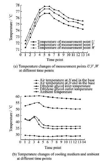
Fig.5 Temperature curves at 50%load
At 80%load,the temperatures of U,V,W are rising just after start(Fig.6).At time point 6,the temperatures tend to be unchanged and finally stable at 102.1℃,105.5℃and 103.7℃,respectively,also lower than the requirement. Before time point 7,the air temperature at Dend in the base is higher than that at Nend,because the air temperature at Dend cools down when the air in the generator is subject to heat transfer,which also occurs in the test at 30%load.The temperatures of ethylene glycol inlet and outlet are raised slightly at the beginning and then decreases until unchanged.The final difference between the temperatures of the outlet and the inlet are 3.0℃,due to some interferences,similar to that test at 50%load.

Fig.6 Temperature changes at 80%load
As is shown in Fig.7,the temperature change trend at 100%is similar to those in the three previous tests.The winding temperature climbs higher from the start and becomes flat after time point 10.The temperatures of U,V,W are stable at 122.8℃,126.5℃and 125.0℃,respectively,a little higher than the threshold of 120℃.In the test,the air temperatures of Nand Dends are the same road as those in the threeprevious tests,and their final stable values are 73.4℃and 65.1℃,respectively.The temperatures at the ethylene glycol inlet and outlet change slightly and finally go along 37.3℃and 41.2℃,respectively,the difference of which are 3.9℃.
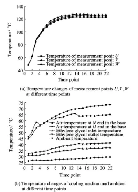
Fig.7 Temperature changes at 100%load
As is shown in Figs.7,8,the temperatures of U,V,Whave the same changing trend as the above test.At the beginning of the test,the winding gets higher temperature as the generator loss is increasing.After a certain period,the temperatures of U,V,Wdo not fluctuate and stay at 123.5℃,128.8℃and 119.1℃,respectively,where the former two are higher than 120℃. And the highest temperature of the three is that of Vin both cases,and the difference of the two maximums are 2.3℃.Two units are produced based on the same specifications,which removes the possibility of factors causing big errors.The sequence set by the temperatures from high to low are measurement points V,U,Win Fig.7(a)but measurement points V,W,Uin Fig.6(a). This is mainly caused by minor differences in operations and test errors and cannot affect final results.In Fig.7(b),the temperatures at Nend,D end,ethylene glycol inlet and outlet waved relatively small.The air temperatures at Nand D ends finally stay at 69.6℃and 57.9℃,respectively,lower than those at 80%load(Fig.6(b)),because bearing manufacturing processes at 100% load are better than those at 80%load,and the friction and the loss at the bearings at 100%load are smaller than those at 80%load.The temperatures of ethylene glycol inlet and outlet finally stay at 35.8℃and 39.7℃,respectively,with a difference of 3.9℃.

Fig.9displays temperatures of four measurement point in the test room.The four exhibit a same changing trend and all become stable around 42℃.
Although the temperature of the generator at 100%load is higher than the design value,the actual environmental temperature is about 9℃orless,much lower than the test room temperature at 100%load as 42℃test.Moreover,some experiment errors and unknown thermal resistance are not considered in the theoretical design process.Therefore,the proposed cooling system has certain valuable feasibility and applicability. Further research will focus on the optimization of geometry structure parameters of the coolingchannel or the flow parameters.Also,from Fig.7we can see that the ethylene glycol solution temperature and the air temperature at Dand Nends are much lower than the winding temperature,which means the stator cooling design can cool the winding and the hollow wires with cooling medium can be set in the winding.

Fig.9 Temperature changes of the test room at different time points
4 Conclusions
A novel cooling system for a 3MW winddriven generator model is proposed.A test platform is built to investigate the cooling performance.Some conclusions are drawn as follows:
(1)The generator temperature at 30%,50% and 80%loads satisfy the requirement but that at 100%load is little higher,although 100%load seldom happens.
(2)The conceptual design of stator cooling channels can basically meet the demand,but small improvements are necessary.It is possible to cool the inner thermal resistance by improving manufacturing processes and cool the winding in-tensively with hollow wires set in the winding.
References:
[1] LI X,YU Z.Development of offshore wind power[J].Acta Energiae Solaris Sinica,2004,25(1):78-84.
[2] LIN H,GUO Y,SUN B,et al.Overview of offshore wind power key technologies[J].Journal of Southeast University,2011,41(4):882-888.
[3] JORN R.Cooling arrangement for an offshore wind energy installation:United States,10/854924[P]. 2004-05.
[4] ARIFUJJAMAN M,IQBAI M.Comparison of wind turbines regarding their energy generation[J].Power Electronics Specialists Conference IEEE,2002(1):6-11.
[5] FANG C.Practical problems and coping strategies of wind power industry in China[J].World Non-Grid-Connected Wind Power and Energy Conference,2009,12(2):1-5.
[6] LIAO Y,LIPO T A.A new doubly salient permanent magnet motor for adjustable speed drives[J]. Proceeding of Electric Machines &Power Systems,1994,22(2):259-270.
[7] WEN J,LI Y.Study of flow distribution and its improvement on the header of plate-fin heat exchanger[J].Cryogenics,2004,44(8):823-831.
[8] ZHANG J,LIU B,XU H.Experimental investigation on flow and heat transfer of jet impingement inside a semi-confined smooth channel[J].Transactions of Nanjing University of Aeronautics and Astronautics,2014,31(1):16-25.
Mr.Qian Xiaohui is currently a Ph.D.candidate of Man-Machine-Environment Engineering in College of Aerospace Engineering at NUAA.He received his first degree and M.S.degree at NUAA.His research interest focuses on environment control.
Dr.Jiang Yanlong is currently aprofessor and doctoral supervisor at NUAA.His research interests include environment control,reliability analysis of nuclear power system and high efficient technology for high heat flux.
Mr.Cheng Danfeng is currently a M.S.candidate of Man-Machine-Environment Engineering in College of AerospaceEngineering at NUAA.He received B.S.degree at NUAA.His research interest focuses on environment control. Ms.Liu Juan is currently a M.S.candidate of Man-Ma-chine-Environment Engineering in College of Aerospace Engineering at NUAA.He received B.S.degree at NUAA. His research interest focuses on environment control.
(Executive Editor:Xu Chengting)
TK83 Document code:A Article ID:1005-1120(2016)02-0180-07
*Corresponding author,E-mail address:jiang-yanlong@nuaa.edu.cn.
How to cite this article:Qian Xiaohui,Jiang Yanlong,Cheng Danfeng,et al.Experimental analysis of a cooling system for wind-driven generator stator[J].Trans.Nanjing Univ.Aero.Astro.,2016,33(2):180-186.
http://dx.doi.org/10.16356/j.1005-1120.2016.02.180
 Transactions of Nanjing University of Aeronautics and Astronautics2016年2期
- Transactions of Nanjing University of Aeronautics and Astronautics的其它文章
- Jet Noise Reduction of Double-Mixing Exhaust System
- Grey Incidence Analysis Applied to Civil Aircraft Customization Process
- Gas Flow Development Through Tandem Heat Exchangers Inside Exhaust Nozzle by Using Porous Medium Model
- Heat Transfer Coefficient of Film Cooling with Ellipse-Shaped Tab
- Optimal Control of Reinforced Plate Based on the Minimum Energy
- Numerical Analysis of Refueling Drogue Oscillation During Refueling Docking