
Parachute dynamics and perturbation analysis of precision airdrop system
2016-11-23 06:10GaoXinglongZhangQingbinTangQiangang
CHINESE JOURNAL OF AERONAUTICS 2016年3期
Gao Xinglong,Zhang Qingbin,Tang Qiangang
College of Aerospace Science and Engineering,National University of Defense Technology,Changsha 410073,China
Parachute dynamics and perturbation analysis of precision airdrop system
Gao Xinglong,Zhang Qingbin,Tang Qiangang*
College of Aerospace Science and Engineering,National University of Defense Technology,Changsha 410073,China
To analyze the parachute dynamics and stability characteristics of precision airdrop system,the fluid–structure interaction(FSI)dynamics coupling with the flight trajectory of a parachute–payload system is comprehensively predicted by numerical methods.The in flation behavior of a disk-gap-band parachute is speci fically investigated using the arbitrary Lagrangian–Euler(ALE)penalty coupling method.With the available aerodynamic data obtained from the FSI simulation,a nine-degree-of-freedom(9DOF)dynamic model of a parachute–payload system is built and solved to simulate the descent trajectory of the multi-body dynamic system.Finally,a linear five-degree-of-freedom(5DOF)dynamic model is developed,the perturbation characteristics and the motion laws of the parachute and payload under a wind gust are analyzed by the linearization method and veri fied by a comparison with flight test data.The results of airdrop test demonstrate that our method can be further applied to the guidance and control of precision airdrop systems.Ⓒ2016 Chinese Society of Aeronautics and Astronautics.Production and hosting by Elsevier Ltd.This is an open access article under the CCBY-NC-ND license(http://creativecommons.org/licenses/by-nc-nd/4.0/).
1.Introduction
Parachutes are widely used in modern smart airdrop systems to decelerate and stabilize the payload.1–4For the past few decades,applications of smart technology in decelerator systems were still at the exploration stage and were mainly developedfor the aerial delivery and airdrop missions.Since the 1990s,the U.S.Army has developed several precision airdrop systems by implementing a guidance,navigationamp;control(GNamp;C)system and smart actuator in the parachute and parafoil.5–7Research is still under way on methods and materials used in parachutes and airdrop systems to guide and control parachute flight in order to achieve optimum performance to meet the mission requirements.8Based on the specific requirements of different missions,several types of parachute–payload systems have been designed and tested,9among which the rotating parachute–payload system stands out as a common configurations for smart submunitions that are required to perform a target maneuver operation.However,our airdrop test results show that the stability of the parachute airdrop system often has difficulty in target identification.
The stability of the parachute system has proven to be one of the most difficult aspects of modeling parachutes because of different stability modes.A two-dimensional(2D)parachute model has been developed to compute various characteristics pertaining to the steady descent of a parachute system by investigating the effects of wind on parachute oscillation using measured wind profiles.On the basis of a typical five rotational-degree-of-freedom model of the parachute system,the dynamic stability problem has been theoretically and experimentally investigated.10The results revealed that during static tests a parachute with less stability vibrated with high frequency and considerable amplitudes when kept at constant angles of attack.Thus it became a significant issue to determine the influence of the parachute's dynamic stability,like the canopy–payload coupling,with added fluid mass components and geometrical porosity,among others.11,12The relationship of aerodynamic and inertial parameters with the lateral stability characteristics of a gliding parachute has been analyzed.13The multi-body dynamics methodology has remarkably promoted the development of trajectory planning and stability modeling of parachute systems,although the accuracy of these problems still mainly depends on the profound insights of the aerodynamic characteristics around the parachute and payload,in both the static and dynamic states.14,15
For mission design,however,good estimates of the aerodynamics of the parachute systems are not easy goals to achieve.In the past,static and dynamic experimental measurements were employed to help the designers obtain optimal solutions.16–18In the recent years,computational simulations of parachute systems have gradually played a predominant role in the prediction of dynamic behaviors,and various approaches and numerical methods have been developed to model and perform the simulation of parachute aerodynamics and fluid–structure interaction(FSI)behavior.During both the inflation and steady descent stages,the parachute dynamics are governed by a coupling between the structural dynamics of the parachute and the surrounding fluid flow.As such,the system must be treated as coupled to gain a proper representation of a holistic dynamic system.
Ongoing research has yielded software that improves the accuracy of computational fluid dynamics(CFD)and computational structure dynamics(CSD),and the aerodynamic characteristics as well as the response of the structure can be comparatively studied,which is beneficial for the trajectory and stability computation of parachute coupling systems.On the basis of the deforming spatial domain/stabilized space–time(DSD/SST)technique,19,20which was applied to three-dimensional(3D)computations soon after its development,21,22FSI modeling of several kinds of parachutes was carried out,including ram-air parachutes,23solid round parachutes,24and complex solid parachute designs.25With the new generation of DSD/SST formulations and space–time FSI techniques,26many additional 3D computations presented by parachute FSI were addressed,27,28including ringsail parachutes and reefed ringsail parachutes,29and the evaluation of the stability characteristics of a parachute based on aerodynamic-moment calculations.30The explicit finite element method is also an efficient tool to replicate the FSI dynamics of parachute systems.With the algorithmic enhancements of the arbitrary Lagrangian–Euler(ALE)penalty coupling method in LS-DYNA,considerable efforts were made in the investigation of parachute related recovery problems and in assessing the performance of parachute inflation.31–37In addition,the simplified ALE FSI method is also used to simulate the inflation process of a folded parachute.38,39Compared with the space–time FSI technique,a semiimplicit method for pressure-linked equations(SIMPLE)algorithm was proposed to analyze the FSI and flow field characteristics of a parachute.39
This paper first presents the analysis of aerodynamic characteristics and an FSI coupling mechanism of a parachute–payload system during a precision airdrop operation.The 3D dynamics behavior of parachute systems during inflation and steady descent state is specifically analyzed using the ALE penalty coupling method within LS-DYNA nonlinear dynamicscode.Then,anine-degree-of-freedom (9DOF)dynamic model of the parachute–payload system is developed,which can be used for the prediction of the trajectory and the stability behavior of the parachute–payload system.Good agreement between the simulation and the airdrop test data provides the necessary verification and validation.Finally,on the assumption that the aerodynamic velocity is constant and perturbations are sufficiently minimal,a linear five degree-of-freedom(5DOF)dynamic model is developed in the steady state.The simulation program has been developed and used to remove the influence of wind gusts,and the equations of the steady states can be applied to analyzing the descent and stability characteristics of a parachute airdrop system.The comparison results proved the efficiency of our method in the guide design of precision airdrop systems.
2.Problem formulation
The spatial motion of a precision airdrop system is chaotic and complicated.Upon payload ejection,the canopy will quickly inflate into a hemisphere shape.Under the effect of the aerodynamic pressure on the surface of canopy,the system is decelerated and guided into a steady state with the payload spinning at a constant rate for target identification.This paper mainly focuses on the forming phase from the opening of the canopy to the steady scanning of the payload.The parachute is a scaled disk-gap band(DGB)parachute(as shown in Fig.1);the construct diameter of the parachute Dc=7.5 m,the vent diameter Dv=0.0738Dc,the width of gap Hg=0.0424Dc,the width of band HB=0.1209Dc,the width of band on gore B=0.02 m,the length of suspension lines L=1.713Dc,and the number of gores N=24.The payload is constructed by a conical head,cylindrical body and six wrap-around fins.

Fig.1 Schematic of disk-gap band parachute.
The parachute–payload system is airdropped from an airship at approximately 1 km altitude.
Before modeling the subsystems,the following simplifying assumptions are needed:
(1)The initial state of the parachute is folded in the axial direction,the influence of fabric interaction is ignored,and the payload is a rigid body.
(2)The parachute may yaw,pitch,or roll relative to the payload.
(3)The behavior of surrounding air flow is fundamentally time-dependent and unsteady.
(4)The trajectory of the parachute system is represented by the movement of the joint connecting the parachute with the payload.
(5)The ground is considered to be flat,non-rotating and fixed in space by taking consideration of the earthifxed reference system as an inertial system.
As shown in Fig.2,the following coordinate systems are used:(A)earth-fixed reference Odxdydzdwith origin Od;(B)parachute-fixed reference Oxpypzpwith origin O;(C)payload-fixed reference Oxbybzbwith origin O.The motion of the system is described by the system translational velocity V0,the angular velocity of parachute Ωpand the payload Ωb.In addition,use the pitching angle θp,yawing angle ψp,rolling angleγpto describe the transformation relation from parachute-fixed reference Oxpypzpto earth-fixed reference Odxdydzdand denote the transformation matrix assimilarly,use the Euler angle θb,ψband γbto describe the transformation relation from payload-fixed reference Oxbybzbto earthfixed reference Odxdydzdand denote the transformation matrix asthe transformation relation from payload-fixed reference Oxbybzbto parachute-fixed reference Oxpypzpis denoted asis the vector from joint to the mass center of canopy centroid and Lbthe vector from joint to the mass of center of payload body.
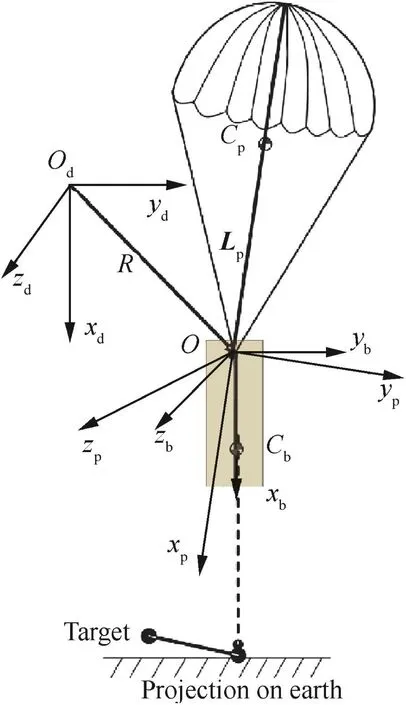
Fig.2 Schematic of parachute–payload airdrop systems.
3.Governing equations
3.1.Multi-body dynamic model
The mass of parachute and the added mass are combined into a general mass matrix,mp,and a general moment matrix of parachute Ip;the increments of aerodynamic force and moments induced by the unsteady motion of parachute are represented by the apparent mass,thus mpand Ipare

where mcrepresents the mass of parachute,(Ix,Iy,Iz)the axial moments of parachute on the joint O,and(a11,a33,a44,a66)the apparent mass of parachute.
Using principlemulti-rigid-body dynamicstheory or method of Dohher and Schilling,40we can describe the parachute–payload system as

where Fp,Mp,Fb,Mbdenote the aerodynamic forces and moments of parachute and payload,Vpdenotes the velocity of parachute,mband Ipdenote the mass and moment matrix of body,Vorepresents the velocity of joint.Further develop the above equations as follows:

An anti-symmetric matrix is introduced for simulation as

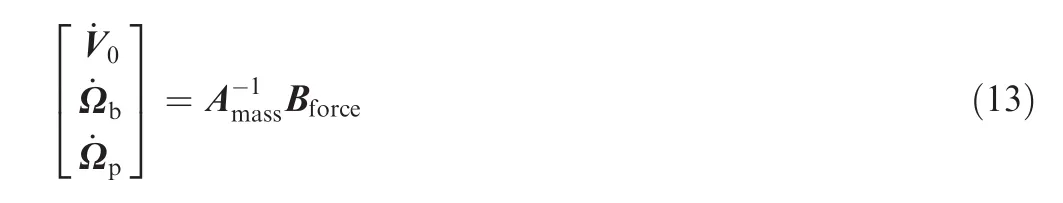
Then the dynamic equations can be further developed.Next introduce the generalized mass matrix of parachute system Amassand generalized force matrix Bforce.

where E is unit matrix and 0 zero matrix.Then,the vector form of parachute–payload system dynamic equation is
Introducing the vector R from connection point to original point,the Euler angle's differential equation of system is
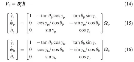
When θ = ±90°,the singularity will appear in Eqs.(15)and(16).Then the Quaternion is introduced into the flight dynamic model to prevent the singularity.The Quaternion is a kind of hypercomplex number composed by four real argument including one real unit and three imaginary units i,j and k,which can be represented as

It is apparent that if q1=q2=q3=0,the Quaternion will degenerate into real number.If q2=q3=0,the Quaternion will degenerate into imaginary number.And the normative equation of Quaternion is

The rotating motion of body represented by Quaternion is

where ωx,ωy,ωzrepresent the axial rotating velocity of body.Then Eqs.(18)and(19)are a group of non-singular linear differential equation,and the relationship between the components of Quaternion and Euler angles is

Subscriptidenotes''pquot;or''bquot;for the equation of parachute and payload.Then the dynamic equation of parachute system can be solved.
3.2.Fluid–structure interactions model
3.2.1.Structure dynamics
Parachute components are mainly flexible and continuous media.Let Ωsbe the spatial domain where superscript''squot;implies the structure,and let ∂Ωsdenote the boundary of Ωs.The governing equation of the structure system is

where ρsis the material density,u the velocity vector of the structure media,σsthe Cauchy stress tensor,and fsthe external body forces acting on the structure.
Considering the large deformation and non-linear dynamic characteristics of the canopy,a special membrane element formulation with a constitutive material model is better suited to it.For thin fabrics,buckling(wrinkling)can occur with the associated inability of the structure to support compressive stresses.The membrane is a 2D shell suited for a three-or four-node element,and the stress–strain relationship of the membrane is given by

where σ1,υ1and E1are the longitudinal stress,Poisson's ratio,and elastic modulus,respectively;σ2,υ2and E2are the traverse stress,Poisson's ratio and elastic modulus,respectively.τ12is the shear stress,G12the shear elasticity and α a non-linear coefficient that can be measured by a stress–strain relationship test.
Additionally,the suspension lines are made of rope and are acted on by drag,gravitational forces,and aerodynamic forces during the inflation process.Therefore,the influence of damping and the non-linear characteristics of the rope should be considered,and thus the dynamic governing equation can be rewritten as
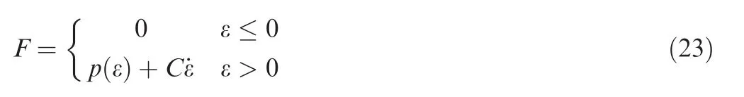
where p(ε)represents the non-linear tensile function of the ropes,and C is the damping coefficient.
3.2.2.Fluid dynamics
The parachute opening velocity in an airdrop process is usually relatively low,and the fluid field can be regarded as an incompressible viscid flow.Let Ωfand(0,T)be the spatial and temporal domains,and ∂Ωfdenote the boundary.By introducing the ALE formulation,the finite mesh can be freely moved.The fluid particle coordinates are Xj(t)(j=x,y,z),where t∈(0,T),thus the Navier–Stokes governing equations for incompressible flow in the reference coordinates are

where v and w are fluid particle velocity and material mesh velocity,respectively,in reference coordinates and fluid density.Eq.(20)is the Euler formulation,and if v=w,the Lagrange formulation can be applied.Thus,the ALE formulation contains both the Euler formulation and Lagrange formulation.Solid elements with the momentum advection advantage are suitable for solving the Navier–Stokes equations for a fluid;the second-order van Leer monotonic upstreamcentered scheme for conservation laws(MUSCL)scheme is used to calculate the values of the solution variables in the transport fluxes to attain accurate second-order monotonic results.This algorithm is accurate,stable,conservative and monotonic.To improve the computational efficiency,the single-point integral of the ALE multi-material method is chosen,instead of the total volume integral.
3.2.3.Penalty coupling
In FSI problems,the computation of the coupling interface is a key technique for the conversion of energy.Utilizing the penalty coupling algorithm,coupling force can be applied in opposite directions of the FSI interface.If dnrepresents the penalty depth of structural nodes at time step t=tn,it is incrementally updated as

where vrelis the reference velocity for the master and slave nodes,and the slave node velocity is vs.The master node velocity can be viewed as a fluid particle within a flood element,with the mass and velocity interpolated from the fluid element nodes using finite element shape functions,thus

The penalty occurs only if ns.dnlt;0,where nsis build up by averaging normals of structure elements connected to the structure node.
Considering the porosity of the canopy fabric,the pressure of porous media can be derived from the Ergun equation of the shell as41

where P is pressure,r the normal direction of the shell,and ε the porosity of the material;the coefficient a(μ,ε)is the reciprocal permeability of the porous shell or viscous coefficient,and b(ρ,ε)the inertia coefficient.
By using the explicit dynamic integral method,the velocities and aerodynamic pressure can be effectively solved satisfying the continuity constraint of Eq.(27);then,the external forces act on the subsystems and dimensionless aerodynamic coefficients can be measured to solve the multi-body dynamic equations.
3.3.Integration
There is no easy way to directly couple the FSI and multi-body dynamic models.The flowchart of this procedure is depicted in Fig.3,and the procedure to simulate the inflation and steady descent phases is shown as follows.
First,the initial velocity is loaded on the joint of the parachute–payload system and the FSI computation begins.Unlike the constant flow velocity of the system with fixed payload in infinite mass inflation,in this paper the payload is freely moving in FSI simulation.
Second,at each explicit dynamic time step Δt,the aerodynamic forces and moments of the system can be written into the transfer data files.With input data from the transferred data file to the 9DOF parameters,for the flight dynamic model,the trajectory simulation will then be triggered.
Third,after the data files of aerodynamic forces and moments are obtained,the multi-body dynamic equation starts to compute and the velocity magnitude of the joint is then updated and reloaded on the parachute–payload system for FSI simulation at the next time step.The iteration loop then continues.During the inflation distance,the canopy is gradually pressurized until it reaches a steady hemisphere profile when it is fully inflated,just at this moment tfdenotes the inflation time.
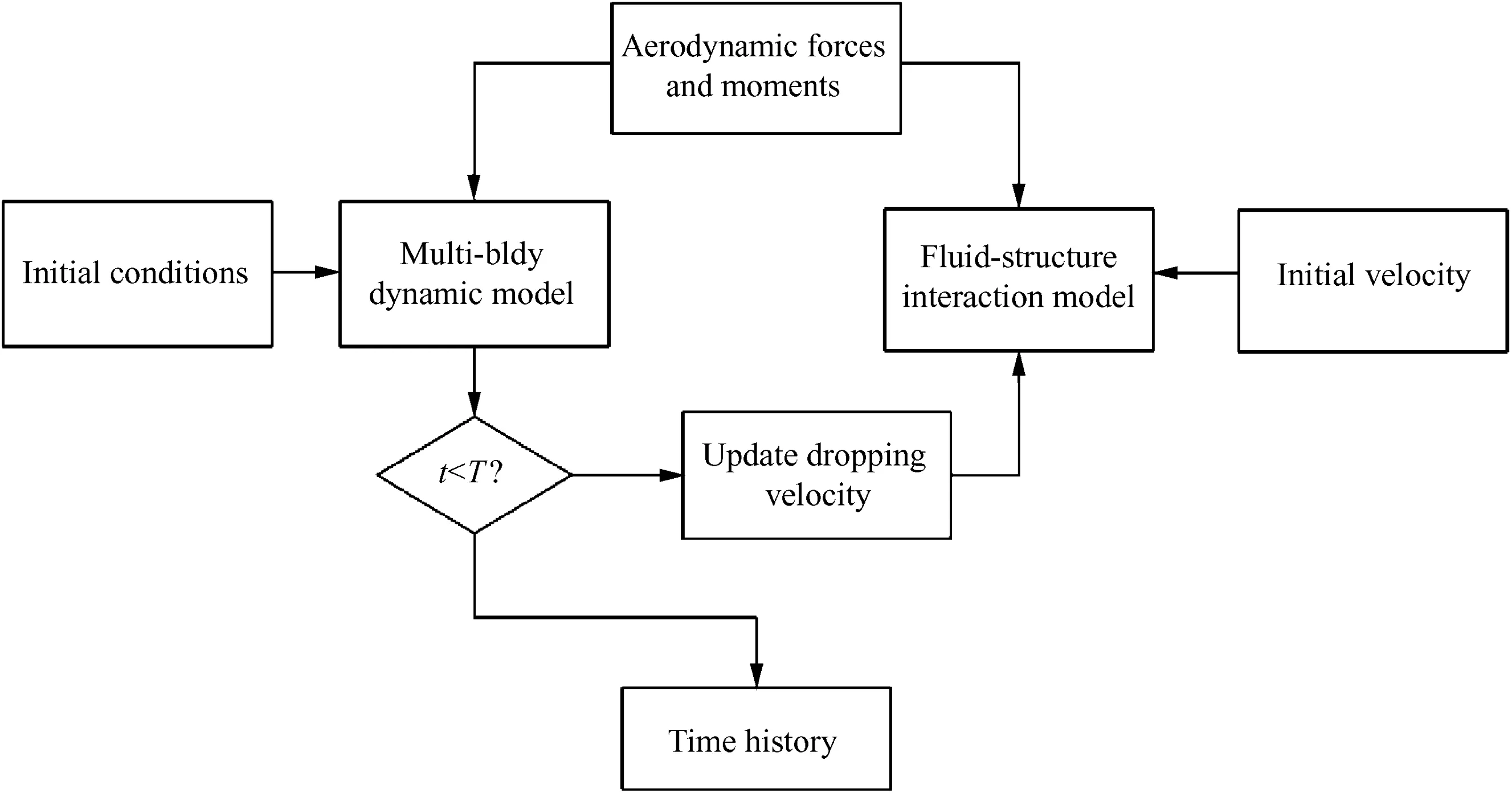
Fig.3 Flowchart of integration model.
The steady descent state begins after tf,and the system velocity converges to a steady value.If t equals to the terminal time,which means the parachute system lands on the ground,the computation of the multi-body dynamic and FSI models is ended and the time history is saved.Thus the FSI and multibody dynamic models are loosely coupled and an integration model is built.
For the FSI simulation,the input k-files are rewritten at each time step and the computation can be continued with the restart capability enabled by the LS-DYNA code.The changing velocity is updated at each time step with the keyword*CHANGE_VELOCITY,which indicates a small deck restart of the LS-DYNA code.Then,the integrated simulation program is developed,tested and used to investigate the FSI and trajectory of the parachute–payload system.
4.Numerical model
4.1.Finite element model
In comparison with the parachute aerodynamics model used in solving the multi-body model as proposed in the literature,the improvement of the simulation model in this paper is the introduction of a flexible parachute and the influence of the FSI phenomenon,which can be achieved by employing the fabric and cable material models based on LS-DYNA nonlinear dynamics analysis code.To accomplish this objective,the finite element model of the parachute–payload system was built as shown in Fig.4.To practically reproduce the initial state of the parachute after stretching out from ejection is theoretically difficult;here,the folded canopy is simplified as a conical shape with an encompassed space to allow the inflow(as shown in Fig.4(a)).The fully inflated model of the parachute is shown in Fig.4(b).The parachute finite element model was constructed by a tetrahedral shell and discrete beam elements,and the rigid payload was simpli fied as a 3D rigid body without considering the structural deformation.

Fig.4 Mesh model of parachute-bomb system.
A column of the fluid field was meshed by a 3D hexahedron element.Thus both the structure and fluid domain were meshed independently(as depicted in Fig.5).The summarized finite element informant is presented in Table 1.
4.2.Material parameters
Furthermore,the canopy is constructed using the fabric material model that is commonly used for an airbag simulation model with LS-DYNA.The fabric material consists of orthotropic composites with permeable,large translation,and nonlinear mechanical characteristics.Table 2 lists the material parameters of the MIL-C-7020 III nylon fabric and suspension lines.
5.Numerical results and discussion
5.1.Parachute inflation dynamics
In order to predict the motion of the parachute–payload system,the aerodynamics of parachute and payload must be known.The finite element model of the parachute–payload system is implemented to evaluate the FSI simulation,which is performed by LS-DYNA,version R7.0.0.Fig.6 first depicts the opening process of the parachute canopy;on the top are the images from the airdrop tests in different inflation states and the bottom is the simulation results of the canopy corresponding to the tested states.It can be seen from the comparison results that the numerical prediction has captured the change of parachute during inflation well;in particular,the''lampquot;shape of the canopy at initial inflating state is vividly simulated.Fig.7 illustrates the results of the projected area of the canopy during inflation.It can be seen from the figures that the parachute is fully inflated at t=0.83 s and then reaches the steady state shortly with a steady drag area.
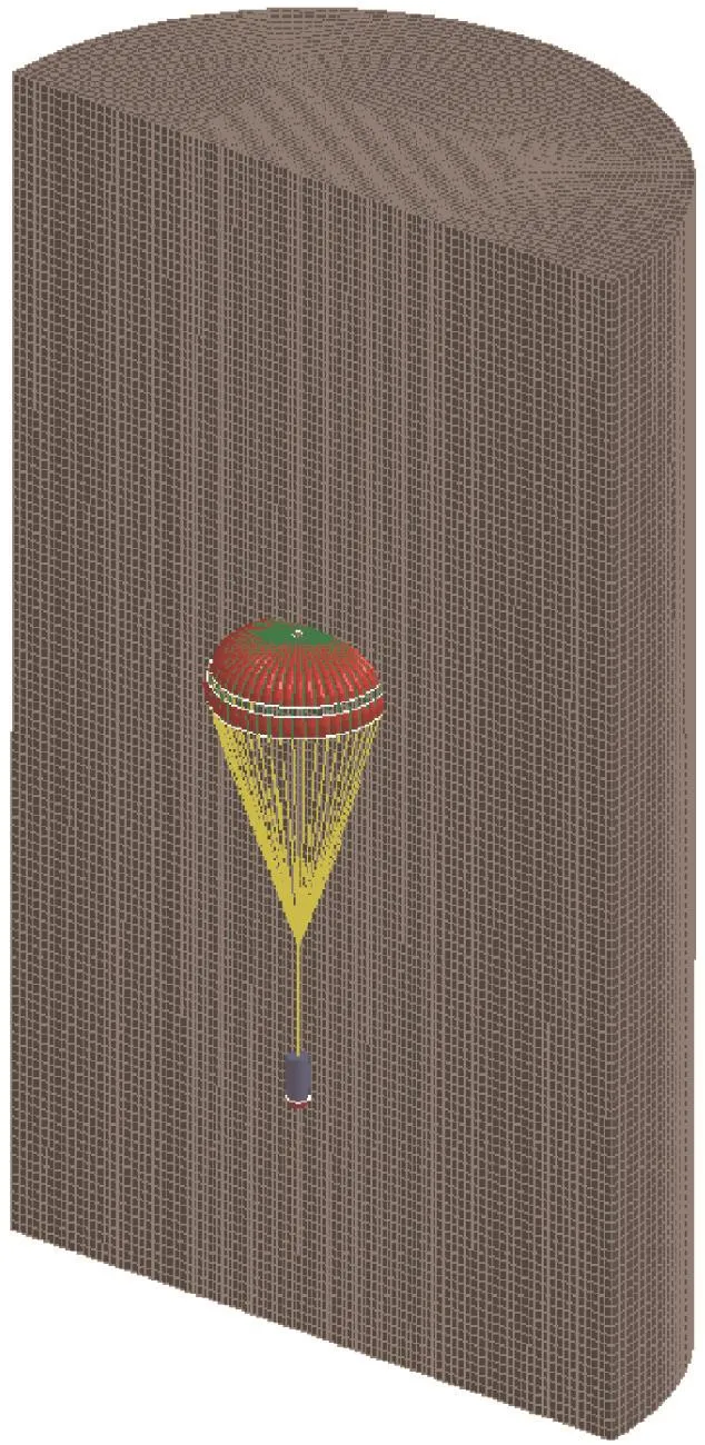
Fig.5 Mesh model of FSI(parachute with payload).

Table 1 Statistical information of parachute system simulation model.

Table 2 Parachute material properties.

Fig.6 3D shape of canopy during parachute inflation process.
5.2.FSI dynamics of parachute–payload system

Fig.7 Numerical results of projected area.
Fig.8 shows the fluid distribution around the parachute,which indicates the unsteady characteristic of fluid during the inflation state.As the continuous airflow passes the parachute,the dimension of the canopy gradually expands up to the maximum drag area,and the growing vortexes move upwards in the air flow direction,with the asymmetry of the conical vortexes appearing.When the canopy fully opens and reaches steady state,the conical vortexes move separately and break into several small vortexes.In addition,the wake trailing the opening canopy is moving close to the speed of the load.As a result,when the load undergoes its maximum deceleration,the wake contacts the apex of the canopy.The recontacting wake results in a negative differential pressure that indents the apex of the canopy.
Figs.9 and 10 show the stress and strain distribution on the canopy.It should be noted that the stress levels near the apex and upper area are remarkably higher than those in the skirt region.However,as a whole,the structural integrity of canopy keeps well,and shows no appearance of stress concentration.Thus the simulation results of the employed FSI model can provide more realistic coupling behavior of the parachute–payload system.
5.3.Aerodynamics coefficients of parachute–payload system
When the parachute reaches the steady descent stage,the FSI calculation continues and the aerodynamic characteristics of the parachute and payload can be investigated.To further comparatively acquire the aerodynamic coefficients of the parachute system at different angles of attack,a group of FSI simulations during steady descent state were performed with different initial attitudes of the parachute–payload system.The initial inflated model of the parachute system for steady simulation can be adopted from the terminal results of the inflation process.Fig.11 shows the aerodynamic coefficients of the steady drag force coefficientsand pitch moment coefficientsof the canopy at different spatial angles of attack;the aerodynamic coefficients of the payload are also depicted in Fig.12,whereandare the drag coefficients of the payload,is the pitch moment coefficient of the payload.
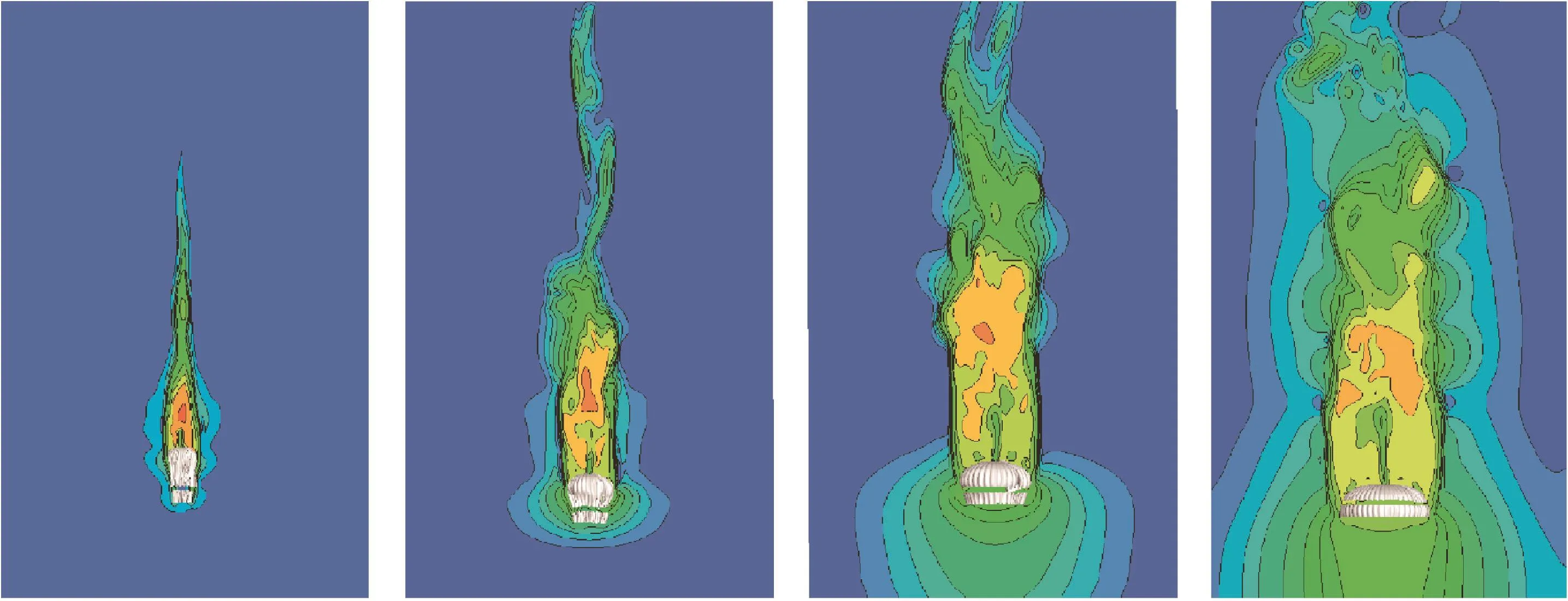
Fig.8 Fluid velocity distribution around parachute.

Fig.9 Stress field of canopy.
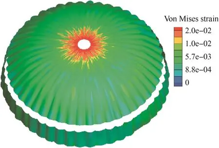
Fig.10 Strain field of canopy.
At zero angle of attack,the drag coefficientis a minimum,approximately 0.62,with no pitch moment.When the parachute oscillates,bothandfirst climb with the increase of angle of attack owing to the asymmetric distribution of aerodynamic forces on the canopy;after reaching the summit at the critical value of angle of attack,andbegin dropping and the drag performance of the canopy starts decreasing.It is obvious that the aerodynamic coefficients of the parachute are still symmetric with the opposite angle of attack,which exhibits good stability of the parachute.For the payload,the aerodynamic coefficients vary linearly during the rigid rotation process.

Fig.11 Aerodynamic coefficients of parachute.

Fig.12 Aerodynamic coefficients of payload.
5.4.Experimental method and trajectory analysis
Under suitable weather with fewer crosswinds,the airdrop experiments were launched eight times from the platform of a remote-controlled helium airship at an altitude of 1000 m above the ground.The measurement system was the gyro on the payload and the ground optical system.The CS41A-2 type single-axis angular rate gyro was installed on the axis line of the payload to record the rolling angle rate in real time.The ground optical measurement system was composed of three computers and two sets of camera systems;the positions of the optical measurement systems are illustrated in Fig.13.The parameters of trajectory and flight information were obtained by imaging processing later,and the spatial 3D positions of parachute–payload system were recorded in real time.
Further,upon the release of main canopy,the payload would rotate at a constant angular rate;this phenomenon was also validated in flight tests.The trajectory of the precision airdrop system mainly depends on the aerodynamic forces and moments that both the parachute and payload experience during the operation.From the results of aerodynamic coefficients from the FSI simulation,the 9DOF model of the parachute–payload system can be solved.Predicted altitude versus time plots is shown in Fig.14,along with the airdrop measurements.A comparison of lateral displacement versus time for the parachute–payload joint is shown in Fig.15.It can be seen from the deviation of lateral displacement that there are still some crosswind influences.Good agreement between the actual and simulated motion is observed.The vertical velocity versus time plot for the parachute–payload system is shown in Fig.16.From the variation trend of the vertical dropping velocity of the system we can know the variation of the canopy's drag area;during the inflation process,the canopy quickly inflates to decelerate the parachute–payload system.When the canopy's area attains steady state,the velocity also slows gradually to a steady value;this value is simply the steady descent velocity of the parachute–payload system,which is a typical design parameter for parachutes.
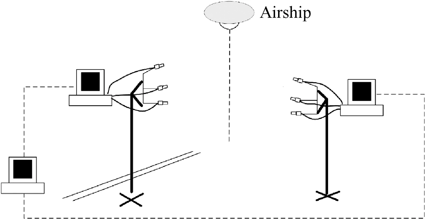
Fig.13 Schematic of optical measuring system's position.
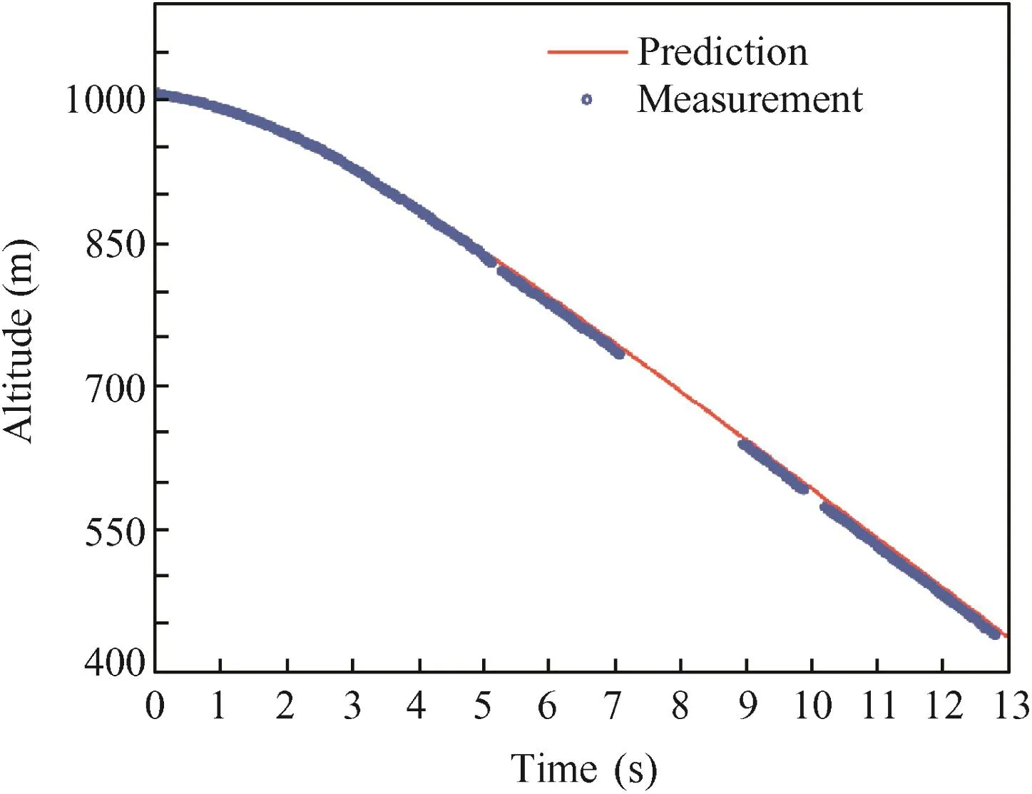
Fig.14 Altitude versus time for joint O of parachute–payload system.
5.5.Perturbation dynamics analysis
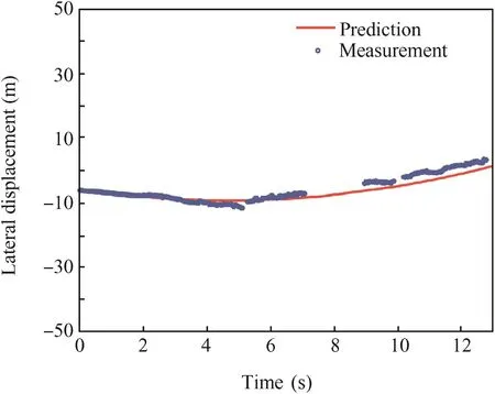
Fig.15 Lateral displacement versus time for joint O of parachute–payload system.

Fig.16 Velocity versus time for joint O of parachute–payload system.

Fig.17 Pitch angle versus time for payload.
The precision airdrop system requires constant angular rotation rate with very small pitch,yaw,and roll oscillations dur-ing the steady descent state;as a result,the influence of oscillations on the variation of steady descent velocity and the roll rate is inevitable.However,for the purpose of linearization,this influence is ignored,considering the yaw and roll perturbations are sufficiently small;we assume that the system descent velocity and the roll rate remain constant,thus allowing the simplifications:

Substituting these values into the 9DOF model of the parachute–payload system arrives at the following form:
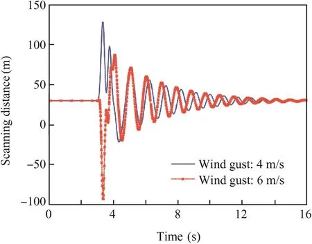
Fig.18 Scanning distance versus time for payload.
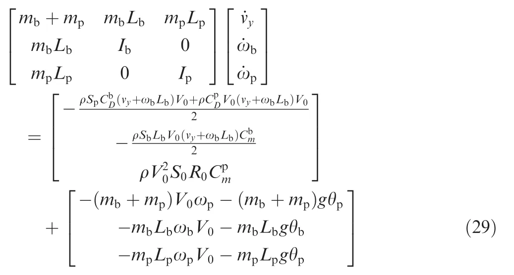
Eq.(29)is the 5DOF model of the parachute–payload system,whereandare drag force coefficients of parachute and bomb,ωband ωpare rotating velocities of parachute and bomb,vyis the velocity of joint and y direction,Sbis the drag area of bomb,and the R0is the radius of bomb's section.This equation contains five unknown quantities:θb,ωb,θp,ωpand vy.
According to the above equation and our airdrop test results,for a stable parachute system the pitch angle of the payload can be written as

where θ0is determined by wind gust and asysdetermined by parachute–payload system parameters.
As shown in Fig.1,only after real-time acquisition of the terrestrial scanning point is finished by the sensors on the payload,can the position of the projective point be calculated.

Fig.19 Euler angles of parachute during oscillation under earth-fixed reference Odxdydzd.

Fig.20 Euler angles of load during oscillation under earth-fixed reference Odxdydzd.
However,the airdrop tests show that the atmospheric turbulence at low altitude causes a regularly larger fluctuation of the scanning point of the payload under the disturbance of a wind gust.The motion characteristics of the parachute–payload system affected by the wind gusts at 4 m/s and 6 m/s were respectively simulated in this study.Fig.17 illustrates the pitch angle versus time for the payload,and Fig.18 illustrates the scanning distance versus time for the payload.Both two figures show that after the disturbance of a wind gust,the payload first oscillates significantly under the effect of the lateral aerodynamic forces;then,affected by the drag forces of the parachute,the payload gradually becomes stable in a fixed time.The flight tests also validated this phenomenon.
The Euler angles of the parachute and payload affected by the wind gust at 6 m/s are illustrated in Figs.19 and 20.Under the small disturbance of wind we know that the attitude of the parachute shows good stability;the wind causes a larger oscillation of the roll motion than those of the other two directions.For the attitude of the load,the payload swings fiercely at the beginning under the act of wind force,but combined with the aerodynamic drag forces from the parachute,the payload tends to keep steady and decays in the rule of index,especially for the roll and pitch angles.The payload shows periodicity in the yaw motion.
6.Conclusions
There exists a significant potential for improving the precision accuracy of a parachute–payload system through the implementation of dynamics analysis.Combined with the ALE penalty method and multi-body dynamics,a monolithic coupling method is developed to numerically study the dynamic behavior of the parachute–payload system.
(1)The computational model employs FSI simulation of incompressible flows coupled with a thin shell structure finite element model.The FSI simulations can reproduce both the 3D shape of canopy inflation and the unsteady flow characteristics around the canopy and structural properties during small oscillation.
(2)Selecting the aerodynamic coefficients of parachute and payload as inputs,the 9DOF dynamic model of the precision airdrop system was solved and compared favorably with the flight measured values.
(3)A perturbation analysis of the precision airdrop system was conducted to eliminate the influence the wind gusts;the data show that pitch oscillations of the parachute–payload system could damp out under the effect of aerodynamic drag from the parachute and a final equilibrium of the subsystems can be achieved.
(4)Good agreements prove the accuracy of this prediction method.The successful airdrop test demonstrates that our coupling method can be potentially applied in the guidance of precision airdrop systems.
In summary,good prediction of parachute dynamics and stability of parachute–payload system can significantly improve the maneuvering ability of an airdrop system.The monolithic method proposed in this paper for the analysis of FSI and perturbation behavior of the parachute–payload system is a complete theoretical method that can be a high-fidelity simulation tool for the design of precise parachute–payload airdrop systems.
Acknowledgements
This study was co-supported by Research Project of Chinese National University of Defense Technology(No.:JC13-01-04)and the National Natural Science Foundation of China(Nos.:51375486 and 11272345).And also thanks for the found support from China Scholarship Council(CSC).
1.White FM,Wolf DF.A theory of three-dimensional parachute dynamic stability.J Aircraft 1968;5(1):86–92.
2.Wolf D.Dynamic stability of a nonrigid parachute and payload system.J Aircraft 1971;8(8):603–9.
3.Edward F.Parachute dynamics and stability analysis of the Queen Match Recovery System.11th aerodynamic decelerator systems technology conference.Reston:AIAA;1991.
4.Anthony C.An analysis of aerodynamic control for direct fire spinning projectiles.AIAA guidance,navigation,and control conference and exhibit.Reston:AIAA;2001.
5.Brown G,Haggard R,Almassy R,Benney R,Dellicker S.The affordable guided airdrop system(AGAS).15th CEAS/AIAA aerodynamic decelerator systems technology conference.Reston:AIAA;1999.p.8–11.
6.Benney R,Barber J,McGrath J,McHugh J,Noetscher G,Tavan S.The joint precision airdrop system advanced concept technology demonstration.18th AIAA aerodynamic decelerator systems technology conference and seminar.Reston:AIAA;2005.p.23–30.
7.Wegereef J,Jentink H.Parafoil characterisation tests with SPADES.18th AIAA aerodynamic decelerator systems technology conference and seminar.Reston:AIAA;2005.p.22–8.
8.Hattis PD,Appleby BD,Fill TJ,Benney R.Precision guided airdrop system flight test results.14th AIAA aerodynamic decelerator systems technology conference.Reston:AIAA;1997.p.3–5
9.Maydew RC,Peterson CW.Design and testing of high-performance parachutes.Paris:AGARD;1991,Report No.:AGARD-AG-319.
10.Doherr K.Theoretical and experimental investigation of parachute-load-system dynamic stability.Proceedings of 5th AIAA aerodynamic decelerator and balloon technology conference.Reston:AIAA;1975.
11.Eaton JA.Added mass and the dynamic stability of parachutes.J Aircraft 1982;19(5):414–6.
12.Cockrell DJ,Haidar NIA.Influence of the canopy-payload coupling on the dynamic stability inpitch of a parachute system.Aerospace design conference.Reston:AIAA;1993.
13.Crimi P.Lateral stability of gliding parachutes.J Guidance Control Dyn 1990;13(6):1060–3.
14.Guglieri G,Quagliotti F.Validation of a simulation model for a planetary entry capsule.J Aircraft 2003;40(1):127–36.
15.Avanzini G,Guglieri G,Torasso A.Multibody analysis of terminal phase for a reentry vehicle:a comparative study.J Aircraft 2012;49(6):1940–52.
16.Shpund Z,Levin D.Static and dynamic coefficients of a cross-type parachute.J Aircraft 1994;31(1):132–7.
17.Guglieri G,Quagliotti F.Low speed dynamic tests on a capsule configuration.Aerosp Sci Technol 2000;4(6):383–90.
18.Levin D,Shpund Z.Dynamic investigation of the angular motion of a rotating body-parachute system.J Aircraft 1995;32(1):93–9.
19.Tezduyar TE,Behr M,Liou J.A new strategy for finite element computations involving moving boundaries and interfaces-The deforming-spatial-domain/space-time procedure:I.The concept and the preliminary numerical tests.Comput Methods Appl Mech Eng 1992;94(3):339–51.
20.Tezduyar TE,Behr M,Mittal S,Liou J.A new strategy for finite element computations involving moving boundaries and interfaces-The deforming-spatial-domain/space-time procedure:II.Computation of free-surface flows,two-liquid flows,and flows with drifting cylinders.Comput Methods Appl Mech Eng 1992;94(3):353–71.
21.Tezduyar TE,Aliabadi S,Behr M,Johnson A,Mittal S.Parallel finite element computation of 3D flows.Computer 1993;26(10):27–36.
22.Tezduyar TE,Aliabadi SK,Behr M,Mittal S.Massively parallel finite element simulation of compressible and incompressible lf ows.Comput Methods Appl Mech Eng 1994;119(S1-S2):157–77.
23.Kalro V,Tezduyar TE.A parallel 3D computational method for fluid-structure interactions in parachute systems.Comput Methods Appl Mech Eng 2000;190(S3-S4):321–32.
24.Stein K,Benney R,Kalro V,Tezduyar TE,Leonard J,Accorsi M.Parachute fluid-structure interactions:3-D computation.Comput Methods Appl Mech Eng 2000;190(s 3-s 4):373–86.
25.Sathe S,Benney R,Charles R,Doucette E,Miletti J,Senga M,et al.Fluid–structure interaction modeling of complex parachute designs with the space-time finite element techniques.Comput Fluids 2007;36(1):127–35.
26.Tezduyar TE,Sathe S.Modeling of fluid–structure interactions with the space-time finite elements:solution techniques.Int J Numer Methods Fluids 2007;54(1):855–900.
27.Tezduyar TE,Sathe S,Pausewang J,Schwaab M,Christopher J,Crabtree J.Interface projection techniques for fluid–structure interaction modeling with moving-mesh methods.Comput Mech 2008;43(1):39–49.
28.Tezduyar TE,Sathe S,Schwaab M,Pausewang J,Christopher J,Crabtree J.Fluid–structure interaction modeling of ringsail parachutes.Comput Mech 2008;43(1):133–42.
29.Tezduyar TE,Takizawa K,Moorman C,Wright S,Christopher J.Space-time finite element computation of complex fluid–structure interactions.Int J Numer Methods Fluids 2010;64(64):1201–18.
30.Takizawa K,Tezduyar TE,Boswell C,Tsutsui Y,Montel K.Special methods for aerodynamic-moment calculations from parachute FSI modeling.Comput Mech 2015;55(6):1059–69.
31.Ben T,Taylor AP.The use of LS-DYNA to simulate the inflation of a parachute canopy.18th AIAA aerodynamic decelerator systems technology conference and seminar.Reston:AIAA;2005.
32.Ben T,Taylor AP,Berland J,Gargano B.The use of LS-DYNA to assess the performance of airborne systems North America Candidate ATPS main parachutes.18th AIAA aerodynamic decelerator systems technology conference and seminar.Reston:AIAA;2005.
33.Coquet Y,Bordenave P,Capmas G,Espinosa C.Improvements in fluid structure interaction simulations of parachutes using LSDyna®.21st AIAA aerodynamic decelerator systems technology conference and seminar.Reston:AIAA;2011.
34.Gao XL,Zhang QB,Tang QG.Transient dynamic modeling and analysis of complex parachute inflation with fixed payload.J Aerosp Eng 2015;28(4):1–14.
35.Gao XL,Zhang QB,Tang QG,Yang T.Fluid-structure interaction simulation of parachute in low speed airdrop.World congress on engineering 2013.London:IAENG;2013.
36.Gao XL,Zhang QB,Tang QG,Li JH.Numerical study on fluidstructure interaction of slot-parachute's inflation process.Acta Aeronaut Astronaut Sin 2013;34(10):2265–76[Chinese].
37.Gao XL,Zhang QB,Tang QG.Reliability assessment of slotparachute inflation based on Bayes theory.J Stat Comput Sim 2014;84(6):1159–72.
38.Yu L,Cheng H,Zhan Y,Li S.Study of parachute inflation process using fluid–structure interaction method.Chin J Aeronaut 2014;27(2):272–9.
39.Yu L,Shi XL,Ming X.Numerical simulation of parachute during opening process.Acta Aeronaut Astronaut Sin 2007;28(1):52–7[Chinese].
40.Doherr KF,Schilling H.Nine-degree-of-freedom simulation of rotating parachute systems.J Aircraft 1992;29(5):774–81.
41.Ergun S.Fluid flow through packed beds.Chem Eng Prog 1952;48(2):89–94.
Gao Xinglongis a Ph.D.candidate at College of Aerospace Science and Engineering,National University of Defense Technology.He received his B.S.degree from Dalian University of Technology,and M.S.degreesin Aerospace Science and Engineering from National University of Defense Technology in 2009 and 2012 respectively.His area of research includes parachute recovery system and multi-body dynamics.
Zhang Qingbinreceived his B.S.degree and M.S.degrees from National University of Defense Technology,and then became a teacher there.His main research interests are multi-body dynamics of aircraft.
Tang Qiangangis a professor and Ph.D.supervisor at College of Aerospace Science and Engineering,National University of Defense Technology.He received the Ph.D.degree from the same university.His current research interests are hypersonic aircraft and multi-body dynamics.
15 June 2015;revised 10 October 2015;accepted 15 January 2016
Available online 9 May 2016
Airdrop system;
Flight dynamics;
Fluid–structure interaction;
Parachute;
Perturbation analysis
*Corresponding author.Tel.:+86 731 84576436.
E-mail addresses:18674853560@163.com(X.Gao),qingbinzhang@sina.com(Q.Zhang),kdtqg@sina.com(Q.Tang).
Peer review under responsibility of Editorial Committee of CJA.
 CHINESE JOURNAL OF AERONAUTICS2016年3期
- CHINESE JOURNAL OF AERONAUTICS的其它文章
- Optimization on cooperative feed strategy for radial–axial ring rolling process of Inco718 alloy by RSM and FEM
- Measuring reliability under epistemic uncertainty:Review on non-probabilistic reliability metrics
- Optimum blade loading for a powered rotor in descent
- Experimental study of ice accretion effects on aerodynamic performance of an NACA 23012 airfoil
- Simulative technology for auxiliary fuel tank separation in a wind tunnel
- Large-eddy simulation of shock-wave/turbulent boundary layer interaction with and without SparkJet control