
Analysis on the crossing obstacle of wheel-track hybrid mobile robot①
2016-12-06 02:39ShuaiLiguo帅立国FeiYanqiongZhengLiyuanGongPengwei
High Technology Letters 2016年1期
关键词:立国
Shuai Liguo (帅立国), Fei Yanqiong, Zheng Liyuan, Gong Pengwei
(*Henan Institute of Science and Technology, Xinxiang 453003, P.R.China)(**Research Institute of Robotics, Shanghai Jiaotong University, Shanghai, 200240, P.R.China)
Analysis on the crossing obstacle of wheel-track hybrid mobile robot①
Shuai Liguo (帅立国)②, Fei Yanqiong**, Zheng Liyuan*, Gong Pengwei**
(*Henan Institute of Science and Technology, Xinxiang 453003, P.R.China)(**Research Institute of Robotics, Shanghai Jiaotong University, Shanghai, 200240, P.R.China)
A novel wheel-track hybrid mobile robot with many movement patterns is designed. According to different environments,it can switch between the pure wheel pattern and the pure track one. According to a homogeneous coordinate transformation matrix, gravity stability and its obstacle performance are analyzed. Its gravity equation and climbing obstacle conditions are established. Experimental results show that this hybrid mobile robot could fully possess the advantages of both the wheel and the track mechanisms and achieve a good obstacle climbing capability.
wheel-track hybrid robot, moving mechanism, obstacle performance
0 Introduction
Mobile robots are useful in many applications of dangerous environments, such as reconnaissance, patrol, vigilance and mine sweeping. There are mostly three kinds of moving mechanisms, like wheel-type structures, track-type structures, and leg-type structures. The wheel-type robot has a brief mechanism, low energy consume, agility movement, and a high migration velocity. But it also has some disadvantages, such as easily skidding in wet slippery soft road surface and weak adaptation in crossing obstacle[1]. The typical wheel-type robots are Nomad polar region exploration vehicle[2]and Shrimp robot[3]. Track-type robot has a big support area, good traction adhesion performance, and high adaptation in crossing obstacle. But its energy consumption is high and velocity is slow. There are some typical track-type robots, like Famous handcart Wheelbarrow EOD robot[4], VIPER[5], modularization EOD robot ASENDRO[6]and so on. The leg-type robot can satisfy some specific performances and has good adaptation in complex terrain, but its structure is too intricacy. DynaRoACH six foot robot[7]and roundness radial symmetry six foot robot[8]are the typical leg- type robots.
Although mobile robots have good advantages in complicated and changeable environment, a lot of problems still exist. Firstly the robots need to improve their stability and ability to adapt different environments. Secondly, the robots need to increase their elasticity due to complicated constructions and big mass. Lastly, because of the existence of large friction resistance between the robot and the road surface, it is important to increase the efficiency[9].
A novel wheel-track hybrid mobile robot is designed. Both the pure wheel pattern and the pure track pattern can be achieved in different conditions. The robot works with a pure wheel pattern when it moves in far distance on the flatness road. On the other hand, the robot works with the pure track pattern when it moves on an uneven road at outdoors.
1 Construction design of wheel-track hybrid mobile robots
1.1 Overall structure
With the symmetry construction, the mobile robot can move freely in narrow channel, without changing the direction or adjusting the body, which improves the operational efficiency. At the same time, it also increases the interchangeability of parts.
In Fig.1, the mobile robot has a couple of differential wheels in the middle of body and a couple of guide wheels which are placed at the front and the back respectively. The robot is driven forward by differential wheels when it works with the pure wheel pattern. The track mechanism can not only drive track to rotate, but also swing around the axis of the driving wheel. The central body of the robot is between the track arms, which is the skeleton of mobile robot and mainly for installing embedded control systems, batteries, sensors and some other necessary devices.

Fig.1 The overall structure of the robot
The robot can switch between the track-type and the wheel-type by swinging track arms to achieve the pure track pattern by swinging track arms down and achieve the pure wheel pattern by swinging track arms up.
1.2 Power transmission system
There are eight degrees of freedom in the power-driven system of the robot, as shown in Fig.2. The wheel part has 2 degrees of freedom. It can realize the high-speed motion, which is driven by a couple of DC motors through the straight teeth reduction gear. The rotation part of four track arms has 4 degrees of freedom, considering great resistance in the movement on poor road conditions. And the swinging part of track arms has 2 degrees of freedom. It is driven by a couple of DC motors through the worm gear reducer. In Fig.1 and Fig.2, the track arms at the same side of the robot body are driven by the same motor and they can swing 360°.

Fig.2 Power transmission system of mobile robot
1.3 Driving device of track arms
Track arms mechanism can drive the tracks to rotate and swing, and both of these two different motions are achieved by rotating around the axis of the drive wheel. The track arms are driven by the reduction motor as shown in Fig.3. The rotary motion of the track is achieved by connecting the inner axis and the driving wheel together with a key, and the inner axis is powered by a couple of bevel gears. The small axis and the worm-gear motor are connected by a rigid coupling, which can keep the track arms driven by the same motor in accordance with each other. The power on the outside axis is transferred from the small axis by a pair of straight teeth reduction gear. On one hand, the reduction gear can take two central drive shafts of the motor apart, which is good for the transmission of different torques. On the other hand, it can increase the driving torque of the track arms.
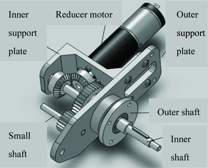
Fig.3 Driving device of track arms
2 The motion analysis of crossing obstacle
2.1 The typical process of crossing obstacles
The track arms of the robot can swing 360°. The robot is abundant in state changes in crossing obstacle process. Fig.4 shows the typical processes.

Fig.4 The typical processes of crossing obstacle
2.2 Analysis on the gravity change of mobile robot
In Fig.5, the Cartesian system o1x1y1z1and o2x2y2z2are established in the revolution axes of track arms, respectively. Coordinate o1x1y1z1is fixed in the central body, and coordinate o2x2y2z2is fixed to the right track arm. P1(x1, y1, z1) is the coordinate of gravity of the middle part, P2(x2, y2, z2) and P3(x3, y3, z3) are respectively the coordinates of gravity of the front track arms and the rear track arms, P*(x*, y*, z*) is the coordinate of gravity of the robot. θ1and θ2are the rotary angles for the track arms relative to the middle part of the body.lis the distance between the shaft and the gravity of the track arm.Lis the distance between the rotary axis of two track arms. The coordinate of gravity P*in coordinate o1x1y1z1is

(1)
M=(m2+2·m2)
(2)


Fig.5 Gravity of the robot
Assuming that two swing arms at the right side are fixed, the relation between x*and y*is obtained
(3)
According to Eq.(3), the gravity (x*y*) of the robot is located within the circle of radius R≤m2·l/M. So, when the length of the track arms and the load capacity meet the conditions, the mass of the track arm m2should be light and the position of gravity of track arms should be close to the rotation axis in order to increase the movement stability.
2.3 Conditions of climbing over obstacle
2.3.1 Climbing over obstacle in translational motion
The ability of robot’s crossing obstacle is defined as vertical that it can just get over. The robot can climb over the obstacle when the vertical line of the gravity overpasses the vertical wall edge in furthest possible erection process[10].
Coordinate system o0x0y0z0is the base coordinate system fixed on the ground, supposing the coordinate P*is (x,y,z) in the base coordinate system o0x0y0z0. In Fig.6, the distance between the wheel centero1of driving wheel of the track arms and the wheel centero3of the small pulley isR. The radius of the small pulley isr. The rotary angle of the coordinate system o1x1y1z1relative to the base coordinate system is θ. The following equation could be established to cross obstacle.

Fig.6 The figure of robot’s crossing obstacle
(4)

when x=0,
h=x*·sinθ-y*·sinθ·tanθ-r·tanθ·tan(θ/2)
-R·cos(60°-θ)·tanθ
(5)
According to Eqs(4) and (5), when the geometry parameters of the robot are fixed, the coordinates of center point P*are the functions ofhand θ. The gravity (x,y,z) of the robot will have different tracks in the base coordinate system o0x0y0z0with different height h. The parameters are given in Table 1.
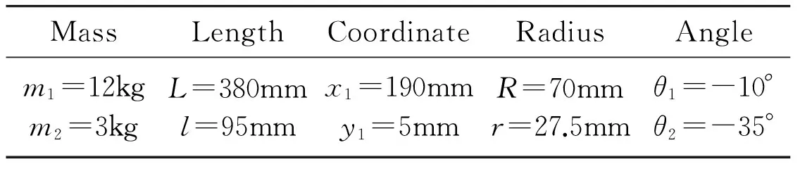
Table 1
The maximum rotary angle θ is 60° because of the robot’s structure. When the robot crosses obstacles, the gravity (x,y,z) in the base coordinate system is shown in Fig.7.

(a)

(b)
If the gravity trajectory of the robot can cross over the planex=0, the robot will have the capacity of crossing the obstacle. In Fig.7, the gravity trajectory of the robot can overpass the planex= 0 only when the height of the obstacle is less than point A. The coordinate of point A on thehaxis is 81.947. So the height of the obstacle that this mobile robot can climb over is 81.947mm.
2.3.2 Climbing over obstacle with swing arms
When it runs into high obstacles, the wheel-track hybrid mobile robot climbs over the obstacle mostly depending on the swinging action of track arms, The critical position of this way is shown in Fig.8.

Fig.8 The critical position of mobile robot climbing over obstacle with swing arms
In Fig.8, where, θ is the angle between the horizontal axis in the coordinate system o1x1y1z1and the horizontal direction.His the height of obstacle, H1is the vertical distance between the swinging arm axis and the bottom of the wheel. l′ is the distance between the swing arm axis and the big driven pulley, r′ is the radius of the big driven pulley, β is the angle between the center line of the swing arm and the axis x1. According to the geometrical relationship in Fig.8, the following is got

+x*·sinθ+y*·cosθ
(6)
In the equation: x*、y*are coordinates of the gravity in coordinate system o1x1y1z1, and Eq.(6) can be arranged,
H=r′+l′·cos(90°-θ-β)+x*·sinθ
(7)
It is obvious that rotary angle θ of the central body and rotary angle β of the track arms have great influence on the height of the obstacle. Donater’=30mm,l’=300mm, H1=60mm, we can obtain the relations between heightHand rotary angle θ, β, in Fig.9.

Fig.9 Relations between the obstacle height and the rotary angles of the body and the swing arms
3 Experiments
Fig.10 illustrates the experiment of the wheel-type movement in room, and Fig.11 shows the experiment of climbing over the obstacle about 80mm. Both of them can be finished successfully. When these four track arms swing 360° around the rotary axis, the trajectory of point P*is shown in Fig.12.

Fig.10 Wheel-type movement of the robot
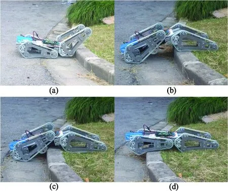
Fig.11 Climbing over the obstacle

Fig.12 The trajectory of the gravity on the mobile robot
4 Conclusions
A new wheel-track hybrid mobile robot is developed. It performs well both in indoor flat environment and outdoors complicated environment. The robot has a variety of movement modes. It can switch between the pure wheel pattern and the pure track pattern. The robot can achieve the pure track pattern by swinging track arms down and achieve the pure wheel pattern by swinging track arms up. The conditions of climbing over obstacle based on the homogeneous coordinate transformation matrix are analyzed. The relationship between the robot’s gravity and the obstacle’s height as well as rotary angles of the track is established. The experiments of the wheel-type movement in door and climbing over the obstacle outdoors are shown. Compared with the similar mobile robot, it has the advantages of smaller volume, compacter structure, higher energy efficiency and so on.
[ 1] Zhu L L, Chen J. A review of wheeled mobile robots research.MachineTool&Hydraulics, 2009, 37(8): 242-247
[ 2] Chopra A, Obsniuk M, Jenkin M R. The nomad 200 and the nomad super scout: reverse engineered and resurrected. In: Proceedings of the 3rd Canadian Conference on Computer and Robot Vision, Quebec, Canada, 2006. 55-55
[ 3] Dian S, Liu T, Liang Y, et al. A novel shrimp rover-based mobile robot for monitoring tunnel power cables. In: Proceedings the 2011 International Conference on Mechatronics and Automation (ICMA), Beijing, China, 2011. 887-892
[ 4] Szynkarczyk P, Czupryniak R, Trojnacki M, et al. Current state and development tendency in mobile robots for special applications. In: Proceedings of the International Conference WEISIC, Bucharest, Romania, 2008, 8: 30-41
[ 5] Vu Q H, Kim B S, Song J B. Autonomous stair climbing algorithm for a small four-tracked robot. In: Proceedings of the International Conference on Control, Automation and Systems, Seoul, Korea, 2008. 2356-2360
[ 6] Edlinger R, Pölzleithner A, Zauner M. Mechanical Design and System Architecture of a Tracked Vehicle Robot for Urban Search and Rescue Operations. Research and Education in Robotics-EUROBOT 2010. Springer Berlin Heidelberg, 2011. 46-56
[ 7] Hoover A M, Burden S, Fu X Y, et al. Bio-inspired design and dynamic maneuverability of a minimally actuated six-legged robot. In: Proceedings of the 3rd IEEE RAS and EMBS International Conference on Biomedical Robotics and Biomechatronics (BioRob), Tokyo, Japan, 2010. 869-876
[ 8] Wang Z, Ding X, Rovetta A, et al. Mobility analysis of the typical gait of a radial symmetrical six-legged robot.Mechatronics, 2011, 21(7): 1133-1146
[ 9] Si Y Y, Zhao X H, Shi C H, et al. Walking mechanism design and kinematic analysis of wheel-tracked composite robot.MachineryDesign&Manufacture, 2013, (7). doi: 103969/j.issn.1001-3997.2013.07.061 (In Chinese)
[10] Merhop W, Hackbarth E M. Tracked vehicle mechanics. Han xuemei. Beijing: National Defence Industry Press, 1989
Shuai Liguo, born in 1968. He received his Ph.D degree and M.S degree in School of Instrument Science & Engineering of Southeast University in 2001 and 1998. He also received his B.S. degree from Xi’an JiaoTong University in 1991. His research interests include the intelligent robots, the technology of tactile display and the virtual reality technology.
10.3772/j.issn.1006-6748.2016.01.002
① Supported by the National Natural Science Foundation of China (No. 61175069, 51075272, 51475300).
② To whom correspondence should be addressed. E-mail: liguo.shuai@126.comReceived on Jan. 14, 2015
猜你喜欢
心声歌刊(2022年1期)2022-06-06
心声歌刊(2022年1期)2022-06-06
歌海(2020年5期)2020-11-16
环球人物(2020年21期)2020-11-09
音乐天地(音乐创作版)(2020年6期)2020-08-18
音乐天地(音乐创作版)(2020年6期)2020-08-18
音乐天地(音乐创作版)(2019年7期)2019-09-19
音乐天地(音乐创作版)(2019年7期)2019-09-19
音乐天地(音乐创作版)(2019年7期)2019-09-19
High Technology Letters(2017年4期)2017-12-19
 High Technology Letters2016年1期
- High Technology Letters的其它文章
- Mixing matrix estimation of underdetermined blind source separation based on the linear aggregation characteristic of observation signals①
- An improved potential field method for mobile robot navigation①
- Robust SLAM using square-root cubature Kalman filter and Huber’s GM-estimator①
- Time difference based measurement of ultrasonic cavitations in wastewater treatment①
- Research on the adaptive hybrid search tree anti-collision algorithm in RFID system①
- Selective transmission and channel estimation in massive MIMO systems①