
Simple Efficient Smart Finite Elements for the Analysis of Smart Composite Beams
2016-12-12 05:39RayDongandAtluri
M.C.Ray,L.Dongand S.N.Atluri
Simple Efficient Smart Finite Elements for the Analysis of Smart Composite Beams
M.C.Ray1,L.Dong2and S.N.Atluri3
This paper is concerned with the development of new simple 4-noded locking-alleviated smart finite elements for modeling the smart composite beams.The exact solutions for the static responses of the overall smart composite beams are also derived for authenticating the new smart finite elements.The overall smart composite beam is composed of a laminated substrate conventional composite beam,and a piezoelectric layer attached at the top surface of the substrate beam.The piezoelectric layer acts as the actuator layer of the smart beam.Alternate finite element models of the beams,based on an“equivalent single layer high order shear deformation theory”,and a“layer-wise high order shear deformation theory”,are also derived for the purpose of investigating the required number of elements across the thickness of the overall smart composite beams.Several cross-ply substrate beams are considered for presenting the results.The responses computed by the present new “smart finite element model”excellently match with those obtained by the exact solutions.The new smart finite elements developed here reveal that the development of finite element models of smart composite beams does not require the use of conventional first order or high order or layer-wise shear deformation theories of beams.Instead,the use of the presently developed locking-free 4-node elements based on conventional linear piezo-elasticity is sufficient.
Piezoelectricity,exact solutions,smart finite element,smart structures.
1 Introductio n
In the quest for developing very light weight high performance flexible structures,a concept has emerged for developing structures with self-controlling and/or selfmonitoring capabilities.Expediently,utilizing the piezoelectric effects Foreward(1981)first attempted to demonstrate the feasibility of using the piezoelectric actuators to damp out the vibrations of a cylindrical fiber glass mast.Subsequently,Bailey and Hubbard(1985),Bruke and Hubbard(1987),Crawley and Leuis(1987),Im and Atluri(1989),Shi and Atluri(1990)successfully reported that the patches of piezoelectric actuators being bonded with the host beams efficiently perform as the distributed actuators of the host beams.Miller and Hubbard(1987)first demonstrated that a layer of the piezoelectric material being integrated with a cantilever beam can act as the distributed sensor of the host cantilever beam.When these distributed sensors and actuators are the elements of the control systems such that the distributed piezoelectric actuators can be activated with a proper control voltage,the host structure attains the self-controlling and self-sensing capabilities.Such flexible host structures possessing built-in mechanism for achieving self-controlling and self-sensing capabilities are being customarily called as smart structures.Since its inception,tremendous research on smart structures has been going on for developing very light weight smart flexible structures.Needless to say that the finite element method has been established as the most widely accepted analytical method for structural analysis and in case of the analysis of smart structures,the same is also true.A brief review of the finite element analysis of the smart structures is now in order.
Shi and Atluri(1990)developed finite element models of smart beams and frames,undergoing large deformations,using a complementary energy approach.Robbins and Reddy(1991)developed a finite element model of an aluminum beam actuated by a piezoelectric layer using a “layer wise displacement theory”.Ha et al.(1992)derived a finite element model of laminated composite plates containing distributed piezoelectric sensors and actuators,using an eight noded brick element augmented with incompatible modes.Hwang and Park(1993)presented a finite element formulation for control of vibration of laminated plates integrated with piezoelectric sensors and actuators.In 1994,Ray,Bhattacharyya and Samanta first derived a finite element model for three dimensional analysis of smart composite plates employing a“high order shear deformation theory”proposed by Lo,Christensen,Wu(1978).Saravanos and Heyliger(1995)derived a finite element model for static and free vibration analysis of composite beams with embedded piezoelectric sensors and actuators using “layer wise displacement theories”.Lin,Hsu and Huang(1996)derived a finite element model for analyzing the deflection control of plates with piezoelectric actuators.Saravanos,Heliger and Hopkins(1997)employed layer wise displacement and electric potential theories for the finite element anal ysis of laminated composite plates integrated with piezoelectric sensors and actuators.B-hattacharya,Suhail and Sinha(1998)developed a finite element model for the free vibration analysis of laminated composite plates coupled with piezoelectric sensors and actuators and the model is based on the “first order shear deformation theory”(FSDT).Chee,Tong and Steven(1999)derived a finite element model based on a“high order displacement field”and a “layer wise linear electric potential theory”for the static analysis of smart composite beams.Varadarajan,Chandrashekhara and Agarwal(2000)derived a finite element model of composite beam based on a “high order shear deformation theory”and implemented the LQG/LTR method for studying robust control of the beams using piezoelectric actuator layer.Valoor,Chandrashekhara and Agarwal(2001)derived a finite element model of composite beams integrated with piezoelectric sensors and actuators and employed neural network for robust control of the beams.Chee,Tong and Steven(2002)again derived a finite element model of smart composite plates based on a“high order shear deformation theory”and a “layer wise electric potential theory”and optimized the piezoelectric actuator orientations for static shape control of the plates.Kulkarni and Bajoria(2003)derived a finite element model using a“high order shear deformation theory”for analyzing active control of curved beams integrated with piezoelectric sensors and actuators.The finite element model derived by Luo and Tong(2004)is based on the Timoshenko beam theory and capable of detecting debonding of the piezoelectric sensors and actuators.Gupta,Seshu and Issac(2004)derived a finite element model of piezoelectrically actuated shells and experimentally verified the model.Ahmed,Upadhyay and Venkatesan(2005)developed a layer-by-layer finite element model of cantilever beam actuated by a piezoelectric layer capturing the continuity of shear stress across the interface between the piezoelectric layer and the host beam.Trindade and Benjeddou(2006)derived a finite element model of smart beams with embedded shear mode piezoceramic actuators and sensors using high order shear deformation theory.Using a layer wise displacement theory and employing an optimal control strategy,Zabihollah,Sedagahti and Ganesan(2007)derived a finite element model for analyzing active vibration control of smart laminated beams.Al-Ajmi and Benjeddu(2008)proposed a discrete layer finite element model for detecting the damage in smart beams.Neto,Yu and Roy(2009)proposed two finite elements for the static analysis of smart beams with piezoelectric actuators.Bendary,Elshafei and Riad(2010)proposed a finite element model of beams coupled with piezoelectric actuators which involved one dimensional isoperimetric hermite cubic shape functions and the lagrange interpolation function.In order to monitor the health of smart structures,Umesh and Ganguli(2011)developed a finite element model of smart composite plates using “ first order shear deformation theory”and investigated the control gains as the damage indicators.Park and Lee(2012)derived spectral finite element model in frequency domain for the dynamic analysis of smart composite beams based on the Euler-Bernouli beam theory.Elshafei and Alraien(2013)presented a finite element formulation of smart composite beams based on a“high order shear deformation theory”.Zhang and Schmidt(2014)carried out geometrically nonlinear finite element analysis of smart composite structures using“first order shear deformation theory”.Song,Kim,Park and Lee(2015)derived a finite element model based on the“first order shear deformation theory”for investigating the guided waves in smart composite beams.
The above review of literature indicates that all the finite element models of smart structures presented so far in the literature are based on some“displacement theories”which include “classical theories”,the “first order shear deformation theory”,“high order shear deformation theories”and “layer-wise theories”.In practice,the smart structures are thin.So,the use of high order shear deformation theories is not essential for finite element modeling of smart structures.Although the layerwise displacement theory provides accurate results for laminated structures when the material properties of the adjacent layers differ significantly,the finite element model based on the layer-wise theory involves excessively large number of nodal degrees of freedom increasing the computational cost of the model.On the other hand,if“first order shear deformation theory”is used,the finite element model needs to introduce the shear correction factor for alleviating the shear locking problem.
Recently,Dong,EI-Gizawy,Juhany and Atluri(2014)developed an efficient locking-free 4-noded finite element for analyzing the laminated beams,based on simple and conventional 2D elasticity theories.This work motivated the authors to develop a new simple 4-noded finite element for analyzing the smart composite structures without using any higher order or layer-wise deformation theories.This paper is concerned with the derivation of such a new smart finite element.Laminated composite beams integrated with a piezoelectric layer at their top surfaces are considered for deriving this new smart finite element.Exact solutions of the overall smart beams are also derived here for validating the new finite element model.Two more finite element models of the overall beams based on an equivalent single layer high order shear deformation theory and a layer-wise high order shear deformation theory are also derived for the purpose of comparison,and for determining the number of the new smart elements required across the thickness of the overall beam.
2 Basic Equations
Figure 1 illustrates a simply supported laminated composite beam integrated with a layer of piezoelectric material at its top surface.The length and the thickness of the beam are designated by L and h,respectively.The thickness of the piezoelectric layer is denoted by hp.The top surface of the beam is subjected to a distributed mechanical load q(x).The piezoelectric layer acts as a distributed actuator layer of the substrate beam.For actuating the substrate beam,the distributed electric potential(voltage)is applied on the top surface of the piezoelectric layer while the surface of the piezoelectric layer being in contact with the top surface of the substrate beam is grounded.The origin of the coordinate system(x−z)is located at one end of the beam such that the lines given by x=0 and x=L represent the ends of the beam and the plane given by z=0 denotes the mid-plane of the beam.The constitutive relations for the converse and the direct piezoelectric effects appropriate for the beam analysis are given by
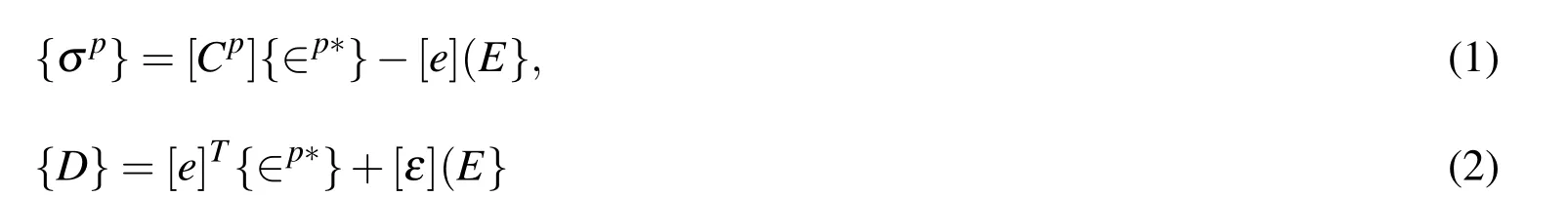
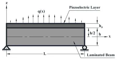
Figure 1:Schematic diagram of a simply supported laminated composite beam integrated with a piezoelectric actuator layer.
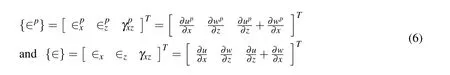
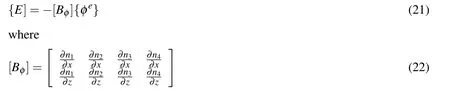
In Eqs.(1)and(2),the state of stresses{σp},the state of assumed strains{∈p∗},the electric field vector{E},the electric displacement vector{D},the elastic coefficient matrix[Cp],the piezoelectric constant matrix[e]and the dielectric constant matrix[ε]are given by

where upand wpare the displacements at any point in the piezoelectric layer along the x-and the z-directions,respectively while u and w are the same in the substrate beam.Based on the displacement fields,the states of strains{∈p}and{∈}at any point in the piezoelectric layer and in the substrate beam,respectively are given by
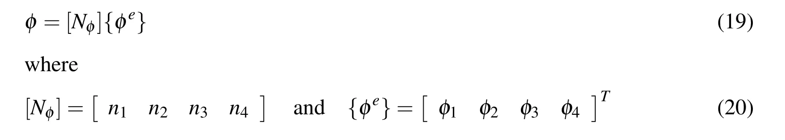
The electric potential function φ(x,z)at any point in the piezoelectric layer is related to the electric fields as follows:

The total potential energy(Π)of the overall smart composite beam of width b is given by
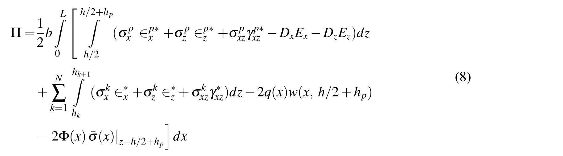
In Eq.(8),Φ(x)and¯σ(x)are the applied distributed electric potential and charge on the top surface of the piezoelectric layer,respectively.Also,hkand hk+1represent the z coordinates of the bottom and the top surfaces of any orthotropic layer of the substrate beam,respectively.
2.1 Derivation of new 4-noded smart finite elements
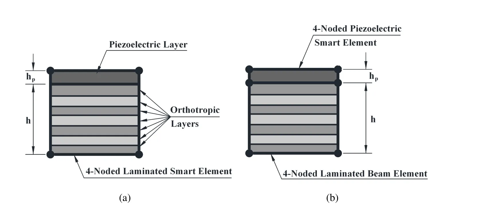
Figure 2:Typical 4-noded finite elements:(a)one piezoelectric smart element and one laminated beam element across the thickness of the overall smart beam(b)one laminated smart element across the thickness of the overall smart beam
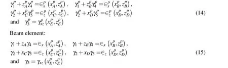
The overall smart composite beam is discretized by four noded isoparametric elements.The finite element mesh can be generated by using two elements across the thickness of the overall beam as shown in Fig.2(a).In this case,the bottom element is composed of the orthotropic layers of the substrate beam and is called the beam element,while the top element is composed of the piezoelectric material only and is called the piezoelectric element.The other option for generating the mesh is to use one element across the thickness of the overall beam as shown in Fig.2(b).This element is a laminated smart finite element in which the top layer is the piezoelectric layer while the other layers are the orthotropic layers of the substrate beam.Thus three types of elements namely the piezoelectric smart element,laminated smart finite element and the beam element are to be formulated for the mesh described by Fig.2.The piezoelectric smart element is characterized by its height hpand length L/n with n being the number of elements along the length of the beam.The length and height of the beam element are L/n and h,respectively.The assumed strain fields in the piezoelectric and the beam elements are given by[Dong,EI-Gizawy,Juhany and Atluri(2014)]:

in which{γp}and{γ}are the matrices of unknown constants for the assumed strain distributions and[A]is a matrix describing the distribution of the assumed strains in the elements.These are given by
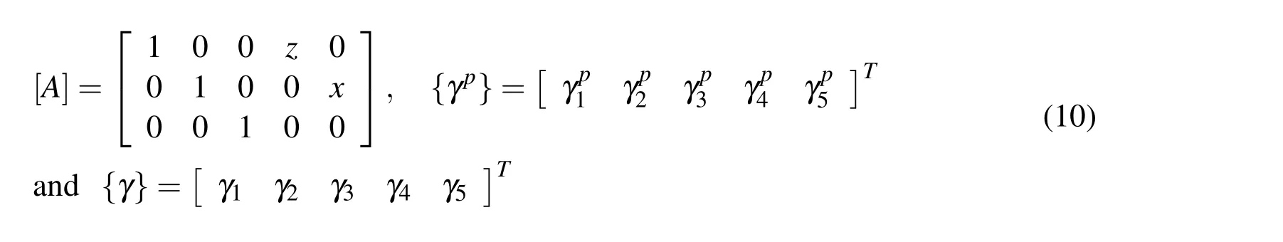
It may be noted from Eqs.(9)and(10)that the assumed normal strains vary linearly with respect to the element-local Cartesian coordinates and the assumed transverse shear strain is constant.It is also to be noted that the assumed bending strain is not coupled with the shear deformation.On the other hand,the displacements at any point in the respective element are given by nodal interpolation:

in which[N]is the shape function matrix,{dpe}and{de}are the nodal displacement degrees of freedom for the piezoelectric element and the beam element,respectively and their explicit forms are as follows:
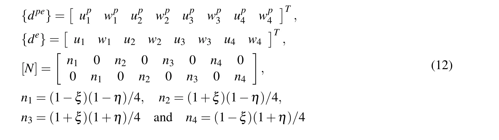
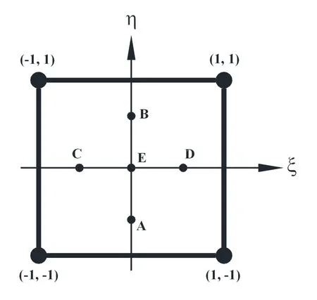
Figure 3:4-noded element with five points of collocation.
where uip,wip(i=1,2,3,4)are the displacements of the i-th node of the piezoelectric element along the x-and the z-directions,respectively;ui,wi(i=1,2,3,4)are the same for the beam element,niis the shape function of natural coordinates(ξ,η)associated with the i-th node of the element.It is evident from Eqs.(11)and(12)that the mesh based normal strains are associated with the mesh based shear strain.Thus it is impossible to cause linearly varying bending strain across the thickness of the beam without causing transverse shear strain.This leads to the so-called phenomenon of shear locking.In order to alleviate this locking problem,Dong and Atluri(2011)suggested to invoke the compatibility between the independently assumed strain and the mesh based strain field based on the displacement field at some pre-selected points of collocation resulting in the solutions of the unknown constants{γp}and{γ}.The five such preselected points of collocation as shown in Fig.3 are considered as follows:
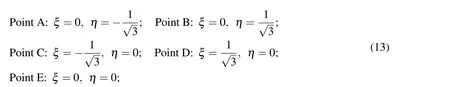
Thus the compatibility of the assumed strains with the mesh based strains based on the displacement fields at the above mentioned five points given by Eq.(13)results in the following conditions:
Piezoelectric element:

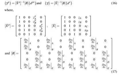
It may again be noted that each row of the matrix[B]is to be computed at each of the five collocated points given by Eq.(13).On substitution of Eq.(16)into Eq.(9),the assumed strains can be expressed in terms of the nodal displacement degrees of freedom as follows:
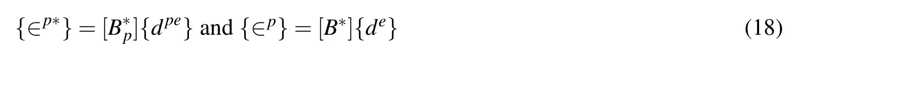
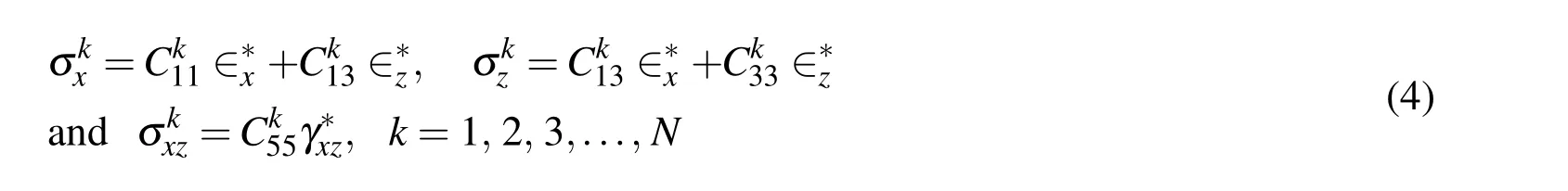
Using Eq.(5)in Eq.(3),it can be written that
The materials being studied here are linear.Thus substituting Eqs.(1),(2),(4),(11),(18),(5)and(6)in Eq.(4)and subsequently applying the principle of minimum potential energy i.e.δΠ =0,the following elemental governing equilibrium equations are obtained:

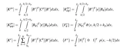

As discussed in[Dong,EI-Gizawy,Juhany and Atluri(2014)],the technique of“over integration”is needed to accurately evaluate the stiffness matrices of laminated elements.In order to take care of the different material properties of each lamina in the substrate,a layer-wise two-point Gauss quadrature in the thickness direction is adopted in this study.In this way,we consider another variable(−1≤ηk≤1)as the natural coordinate in the thickness direction of any(k-th)individual layer,which can be related to the natural coordinate(−1≤η ≤ 1)of the whole beam element as follows:

Thus the elemental stiffness matrix for the substrate beam is to be evaluated as:
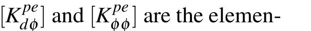
The elemental equations as derived above are assembled in a straight forward manner to obtain the global equations of equilibrium as follows:
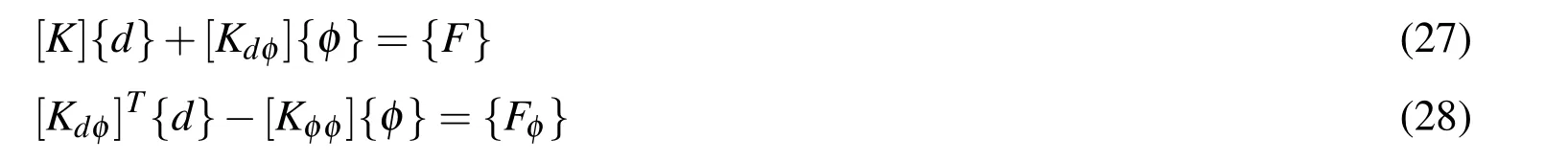
It may be noted that although two sets of equations given by Eqs.(27)and(28)are derived,Eq.(27)is required to compute the nodal displacements if the electric potential is prescribed and Eq.(28)estimates the corresponding nodal charges.
2.2 Exact Solutions of the Smart Composite Beam
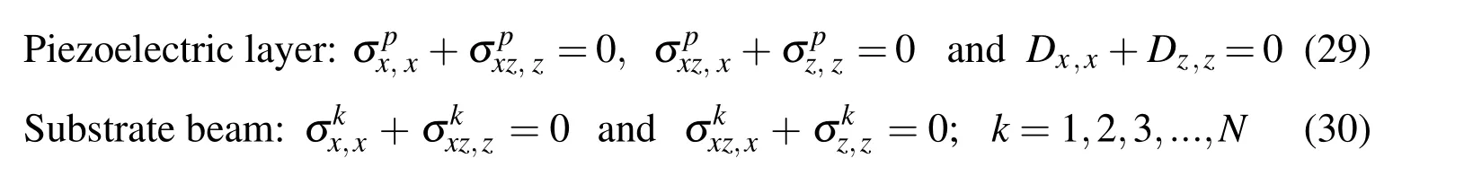
Replacing the assumed strains{∈p∗}and{∈p∗}by the displacement field based strains{∈p}and{∈},respectively in Eq.(8)and applying the principle of minimum potential energy i.e.δΠ=0,the following governing equilibrium equations for the piezoelectric layer and the orthotropic layers of the substrate beam are obtained:
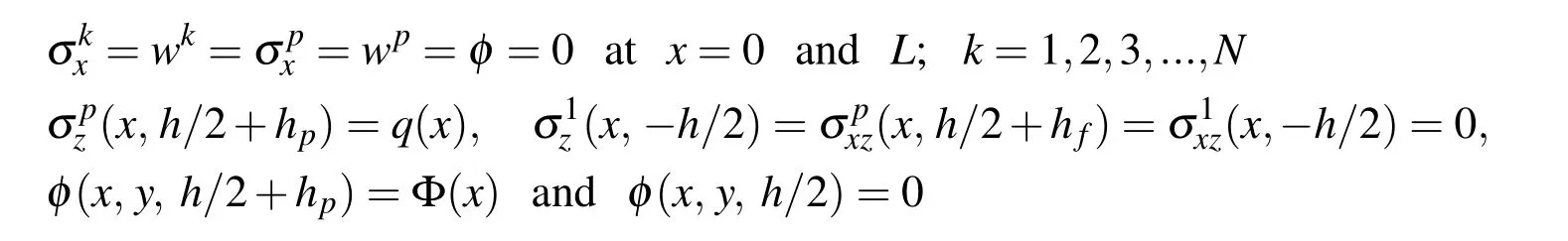
The simply supported boundary conditions obtained from the variational principle are

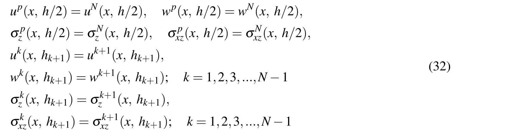
Also,the variational principle yields the following interface continuity conditions:
2.2.1 Exact solutions for the piezoelectric layer
For a particular mode of deformation,the displacement functions and the electric potential function for the piezoelectric solid which satisfy the boundary conditions at the edges of the beam given by Eq.(31)are assumed as

where Up(z),Wp(z)and Φ(z)are unknown functions of z and p=mπ/L with m being the mode number.It may further be assumed that

where U0p,W0pand Φ0are unknown constants to be determined and s is a characteristic parameter.Considering{∈p}and{∈}in place of{∈p∗}and{∈p∗},respectively and subsequently using Eqs.(1),(2),(6),(33)and(34)into the governing equations given by Eq.(29),the following set of homogeneous algebraic equations are obtained:
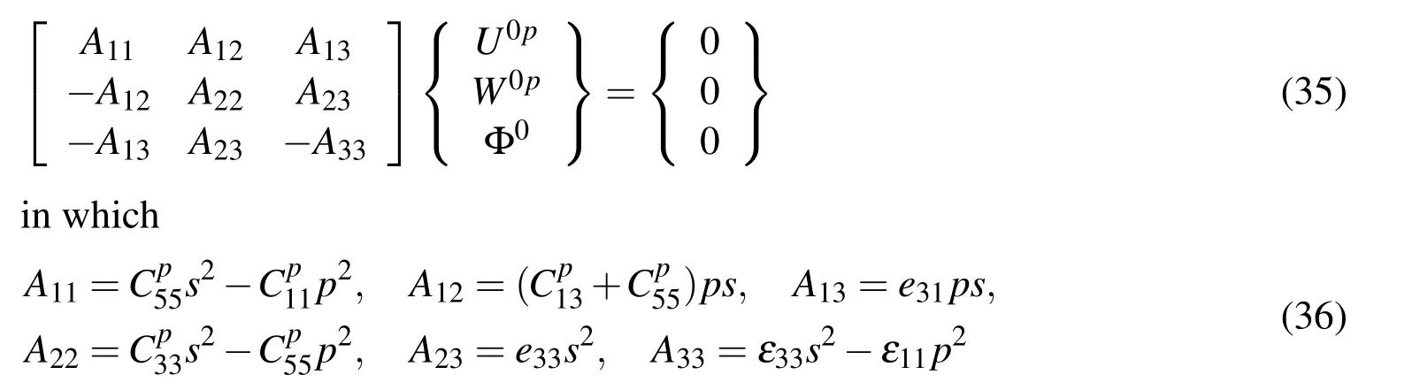
For non-trivial solutions of U0p,W0pand Φ0,the determinant of the co-efficient matrix of Eq.(36)must vanish.This leads to the following sixth degree polynomial equation:

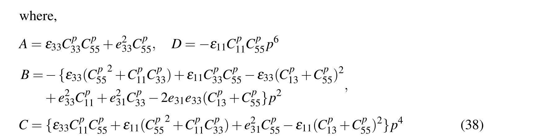
For the geometrical parameters and material properties of the piezoelectric material that is considered for evaluating the numerical results,two real roots and two pairs of complex conjugate roots of Eq.(37)are obtained and these are denoted as

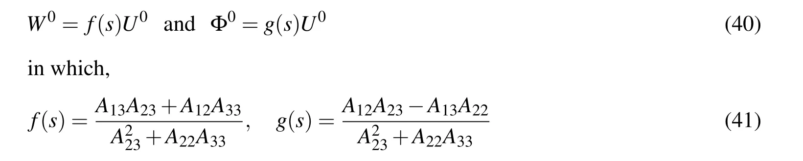
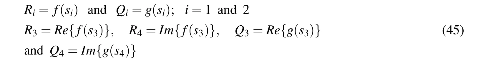
The last two equations of Eq.(35)provide:
Now using the roots of Eq.(37)and the relations given by Eq.(40)in Eqs.(33)and(34),the exact solutions for the displacement fields(up,wp)and the electric potential function(φ)in the piezoelectric layer are derived as follows:
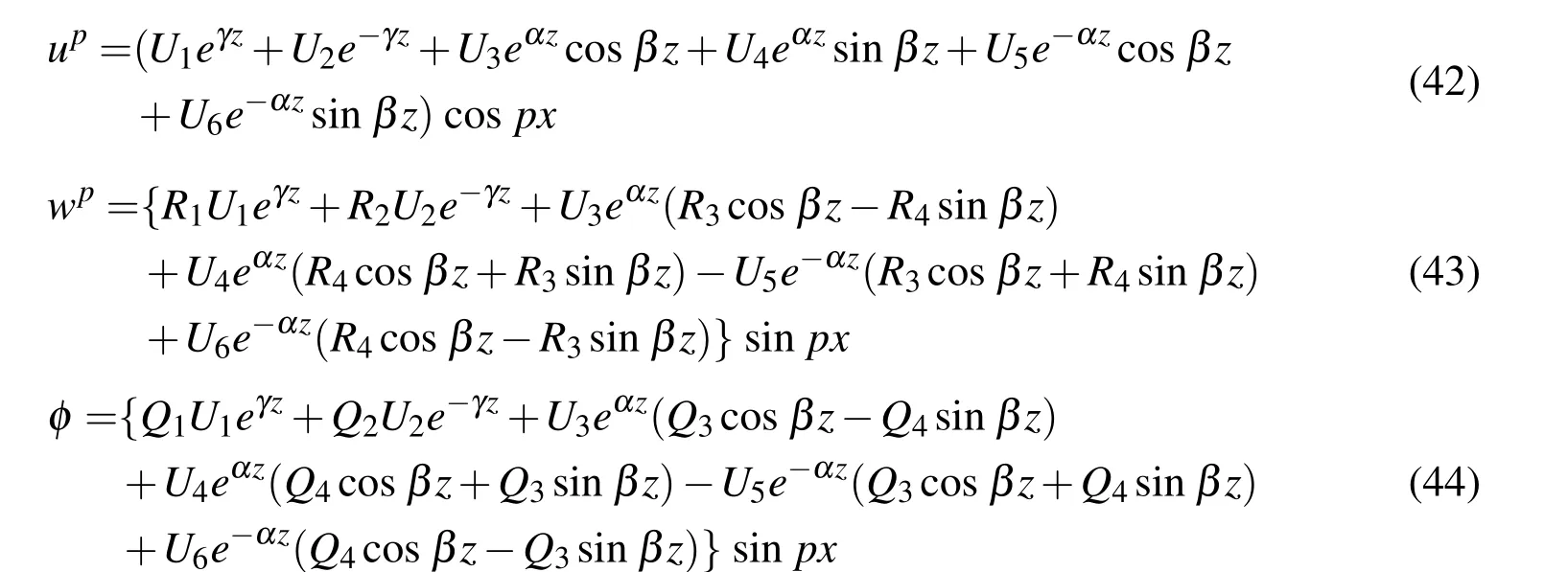
in which Ui(i=1,2,3,..,6)are the unknown constants.The various constants appearing in Eqs.(43)and(44)are given by
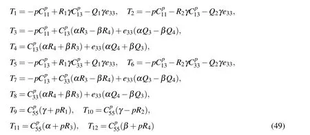
Next,using the constitutive relations given by Eq.(1),the exact solutions for the stresses in the piezoelectric layer are obtained as follows:
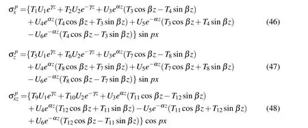
The various coefficients Ti(i=1,2,3,...,12)appearing in Eqs.(46)to(48)are given by
2.2.2 Exact Solutions for the substrate Beam
For a particular mode of deformation,the displacement field for any(k-th)layer of the substrate beam satisfying the boundary conditions given by Eq.(31)can be assumed as

in whichU0k,W0kare the unknown constants for the k-th layer and ris a characteristic parameter.Substitution of Eq.(50)into the governing equations for the k-th
layer of the substrate beam given by Eq.(30)and the use of strain displacement relations result into the following characteristics equation for the layer:
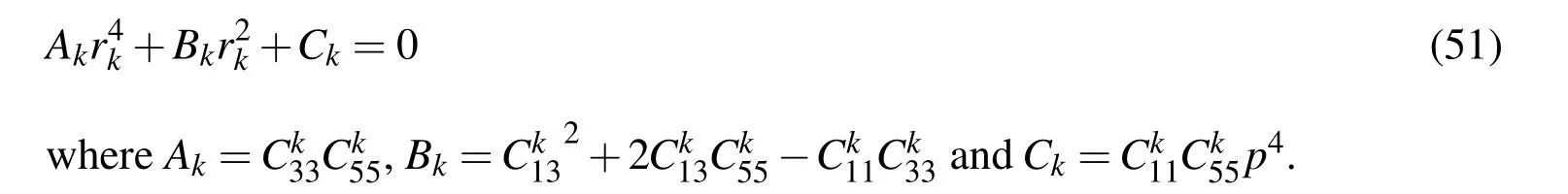
The roots of Eq.(51)are given by
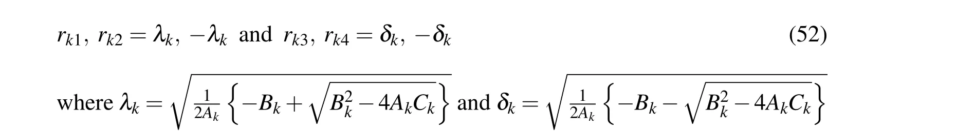
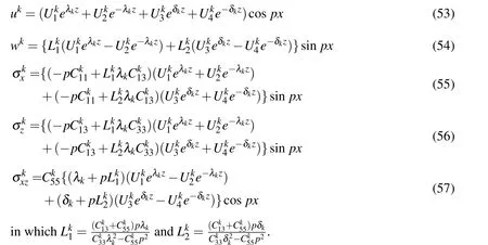
Using Eqs.(4),(50)and(52)and carrying out some algebraic manipulations,the exact solutions for the displacement fileds and the state of stresses at any point in the k-th layer of the substrate beam can be derived as follows:
2.2.3 Solutions of unknown constants
In order to solve the unknown constants(Ui,i=1,2,3,..6;Uki,i=1,2,3,4 and k=1,2,3,...,N),the prescribed boundary conditions are considered as follows:

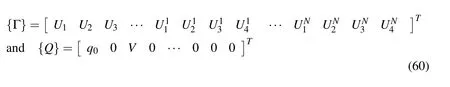
in which q0is the amplitude of the prescribed mechanical load and V is the amplitude of the prescribed electric potential at the top surface of the piezoelectric layer.Satisfaction of the prescribed boundary conditions given by Eqs.(31)and(58)and the continuity conditions given by Eq.(32)leads to the following system of algebraic equations:

in which Kijis the coefficient of Γjwhile the vectors{Γ}and{Q}are given by
3 Finite element model using LHSDT
For the beam analysis,an equivalent single layer high order shear deformation theory(HSDT)proposed by Lo,Christensen and Wu(1978)is given by

in which u0and w0are the translational displacement of any point on the midplane(z=0)of the substrate beam along x and z directions,respectively;θxand θzare the first order rotational variables while φx,γxand φzare high order rotational variables.In this section,a finite element model of the overall smart beam being studied here is derived using a“layer-wise high-order shear deformation theory(LHSDT)”.According to this LHSDT,the displacement field at any point in the substrate beam is given by Eq.(61)while the displacement field at any point in the piezoelectric layer is considered as follows:
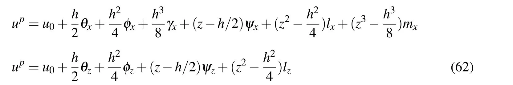
in which ψx,lx,mx,ψzand lzare the generalized rotational coordinates for the piezoelectric layer.The generalized displacement coordinates at any point in the overall beam are expressed in a vector form as follows:

A three-noded bar element is used for implementing this LHSDT to discretize the overall beam.Thus the generalized displacement coordinate vector for the i-th node of the element is given by

and the generalized displacement vector{d}at any point in the element can be expressed in terms of the nodal generalized displacement vector as follows:

in which the shape function matrix[N]and the nodal generalized displacement vector{de}for the element are given by

while[Ni]=niI with niand I being the shape function associate with the i-th node of the element and a(12x12)identity matrix,respectively.The state of strains at any point in the substrate beam and that in the piezoelectric layer of the element can be expressed in terms of the nodal generalized degrees of freedom as follows:

in which the matrices[Z1]and[Z2]and the nodal strain-displacement matrices[B1]and[B2]are presented in the Appendix.The electric potential function which is zero at the interface between the piezoelectric layer and the substrate beam may be assumed as

wherein φ0is the electric potential distribution at the top surface of the piezoelectric layer and can be expressed in terms of the nodal electric potential degrees of freedom{φe}as follows:

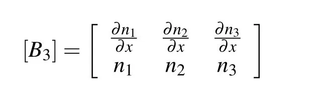
Using Eqs.(7),(68)and(69),the electric filed vector at any point in the piezoelectric layer of the element can expressed as

in which the matrices[Zp]and[B3]are presented in the Appendix.Using Eqs.(8),(65),(67),(69)and(70)and carrying out the explicit integration with respect to z,the total potential energy of a typical element can be expressed as follows:
Now applying the principle of minimum potential energy i.e.δΠ=0,thefollowing elemental governing equilibrium equations of the overall smart beam based on the LHSDT are obtained:
In Eq.(72),the various elemental matrices are given by
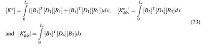
The global equations of equilibrium of the overall smart beam are obtained by assembling the elemental equations in a straight forward manner.However,they can be representd by Eqs.(27)and(28).Using the “equivalent single layer HSDT”given by Eq.(61),the above finite element model(FEM)has been suitably augmented to derive another FEM of the overall smart beam.However,for the sake of brevity the derivation of this FEM is not presented here.
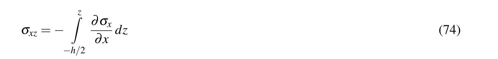
4 Computation of transverse shear stress
The bending stress(σx)computed by the finite element models as derived above can be utilized to compute the transverse shear stress in the overall smart beams by numerically integrating the governing equilibrium equation as follows:
5 Results and discussions
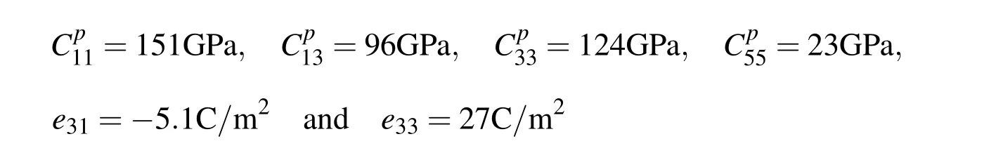
In this section,numerical results are presented to investigate the performance of the new 4-noded smart finite elements derived here.The thickness of the substrate beam and that of the piezoelectric layer are considered as 5mm and 250µm,respectively,while the aspect ratio(L/h)of the substrate beam is considered as 50.The elastic and piezoelectric material properties of the piezoelectric layer(PZT5H)are used as follows[Smith and Auld(1991)]:
The material properties of the orthotropic layers of the substrate beam are used as follows[Pagano(1970)]:
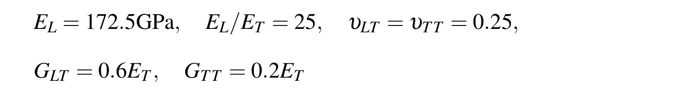
in which the symbols have their usual meaning.The top surface of the overall smart beam is subjected to the sinusoidally distributed upward mechanical load given by Eq.(58)while the value of the amplitude(q0)of the applied load is 50N/m2.Unless otherwise mentioned,the overall smart beam is discretized considering one element for the substrate beam and one piezoelectric finite element across the thickness of the overall smart beam as shown in Fig.2(a).Also 10 elements are considered
along the length of the beam.First a smart beam is considered in which the substrate beam is a single layered beam.Figure 4 illustrates the static responses of this beam when the piezoelectric layer is activated with the prescribed electric potential(voltage)on its top surface.Displayed in the figure are the deflections w(x,0)of the mid-plane of the beam computed by the present new smart finite element model(FEM)and exact solutions.It may be observed from this figure that the piezoelectric layer activated by a negative voltage counteracts the upward deflection of the beam due to the mechanical load only.The responses obtained by the present new smart FEM almost identically match with the exact solutions when the piezoelectric layer is passive(V=0)and active(V/=0).The distributions of the axial normal stress σx(a/2,z)and the transverse shear stress σxz(L/30,z)across the thickness of the substrate of this smart beam have been illustrated in Figs.5 and 6,respectively.It may be observed from these figures that the flexural stress and transverse shear stress computed by the present new FEM match excellently with the exact solutions for the flexural stress and the transverse shear stress when the piezoelectric layer is active(V/=0)and passive(V=0).Figures 7 to 9 illustrate that the deflections w(x,0)of the mid-plane of the cross-ply substrate beams when the lamination sequence in the beams are(0˚/90˚),(0˚/90˚/0˚)and(0˚/90˚/0˚/90p),respectively.It may be observed from these figures that the present new smart FEM accurately computes the deflections of the mid-plane of these substrate beams.Figures 10 and 11 illustrate the comparison of the distributions of the axial normal stress σx(a/2,z)across the thickness of the symmetric(0˚/90˚/0˚)and antisymmetric(0˚/90˚/0˚/90p)cross-ply substrate beams computed by the present new smart FEM with that obtained by the exact solutions.It may be observed that the present new smart FEM accurately computes the bending stress in the multi-layered composite beams when the piezoelectric layer is active(V/=0)and passive(V=0).When compared with the exact solutions,the transverse shear stress σxz(L/30,z)across the thickness of the multilayered symmetric(0˚/90˚/0˚)and antisymmetric(0˚/90˚/0˚/90p)crossply substrate beams computed by the present new smart FEM are indistinguishable from those obtained by the exact solutions as shown in Figs.12 and 13,respectively.
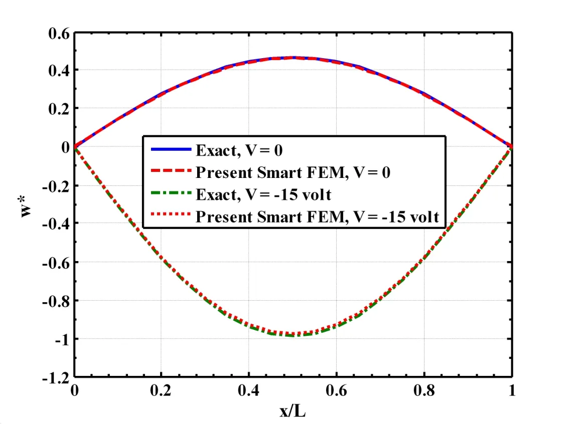
Figure 4:Active static control of shape of a single layered composite beam(L/h=50,hp=250µm,h=0.005m,
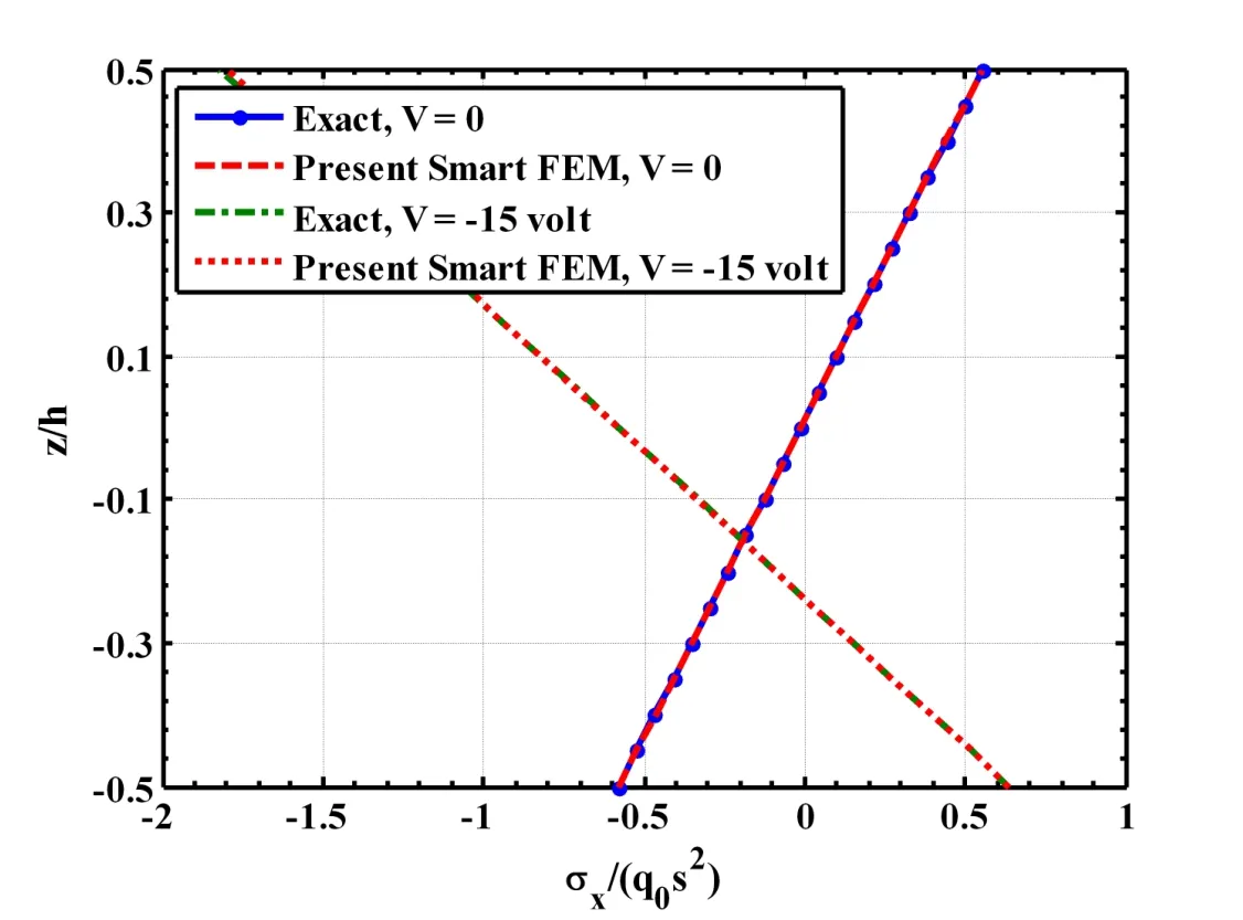
Figure5:Distribution of axial stress across the thickness of the beam with and without actuated by a piezoelectric layer(L/h=50,hp=250µm,h=0.005m,q0=50N/m2).
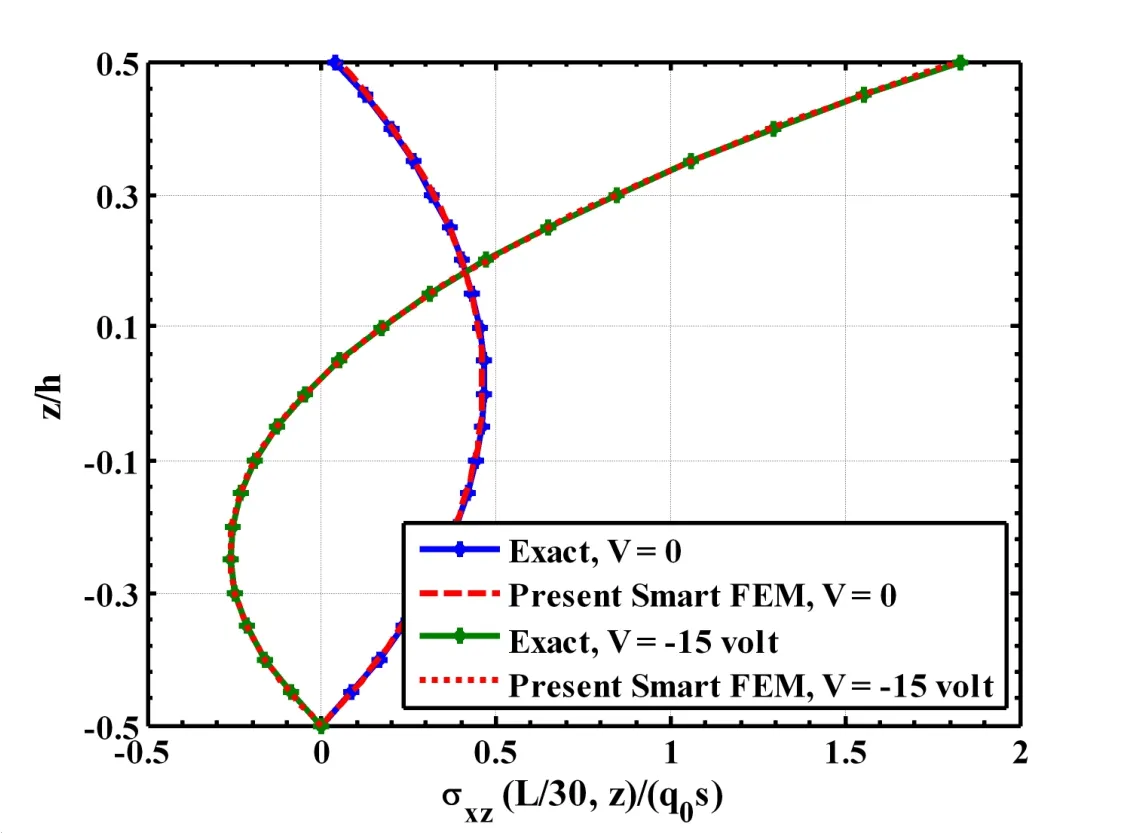
Figure 6:Distribution of the transverse shear stress across the thickness of the single layered composite beam(L/h=50,hp=250µm,h=0.005m,q0=50N/m2).
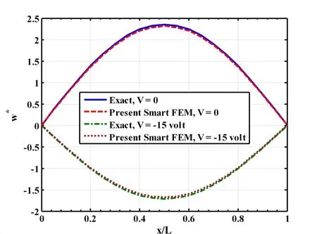
Figure 7:Active static control of shape of a two layered(0˚/90˚)composite beam(L/h=50,hp=250µm,h=0.005m,
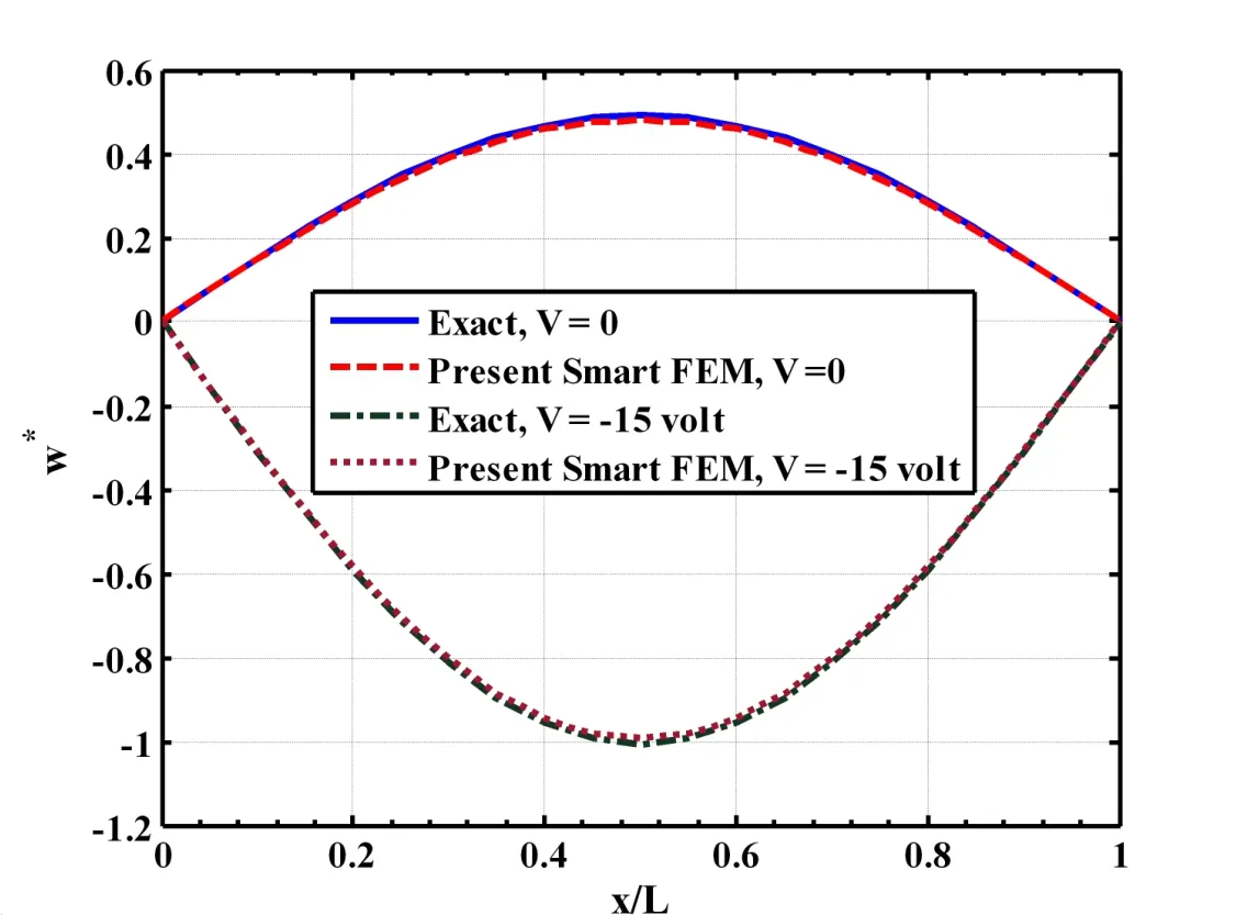
Figure 8:Active static control of shape of a three layered(0˚/90˚/0˚)composite beam(L/h=50,hp=250µm,h=0.005m,
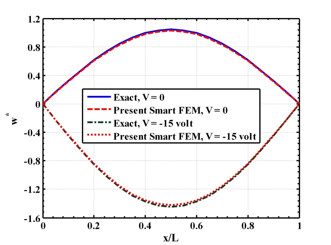
Figure 9:Active static control of shape of a four layered(0˚/90˚/0˚/90˚)composite beam(L/h=50,hp=250µm,h=0.005m
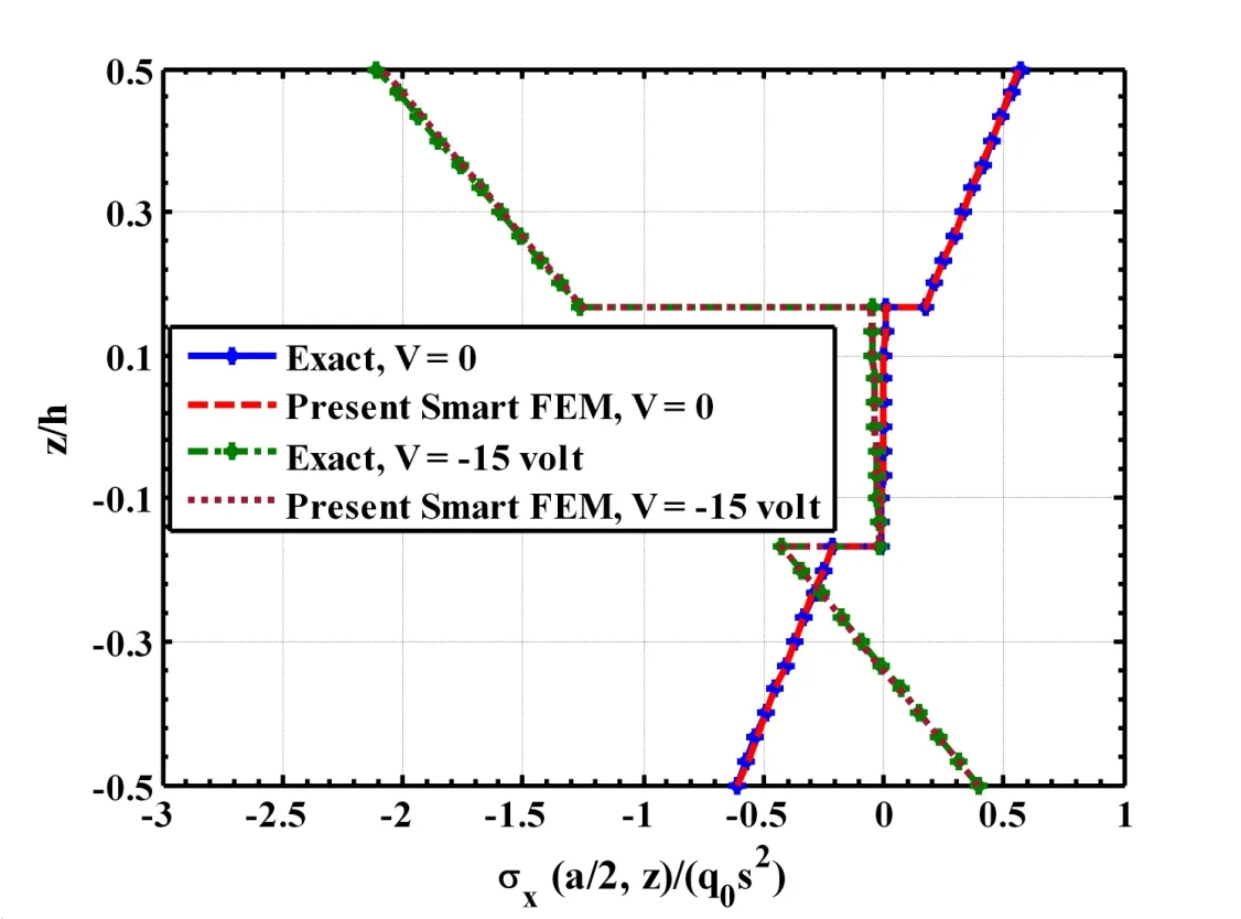
Figure 10:Distribution of the axial stress across the thickness of the three layered(0˚/90˚/0˚)composite beam with and without actuated by a piezoelectric layer(L/h=50,hp=250µm,h=0.005m,q0=50N/m2).
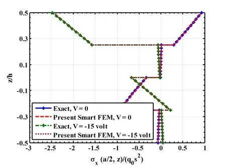
Figure 11:Distribution of the axial stress across the thickness of the four layered(0˚/90˚/0˚/90˚)composite beam with and without actuated by a piezoelectric layer(L/h=50,hp=250µm,h=0.005m,q0=50N/m2).
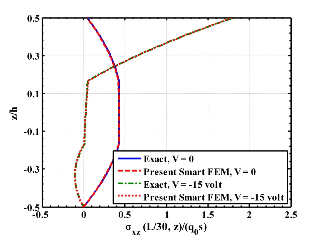
Figure 12:Distribution of the transverse shear stress across the thickness of the three layered(0˚/90˚/0˚)composite beam(L/h=50,hp=250µm,h=0.005m,q0=50N/m2).
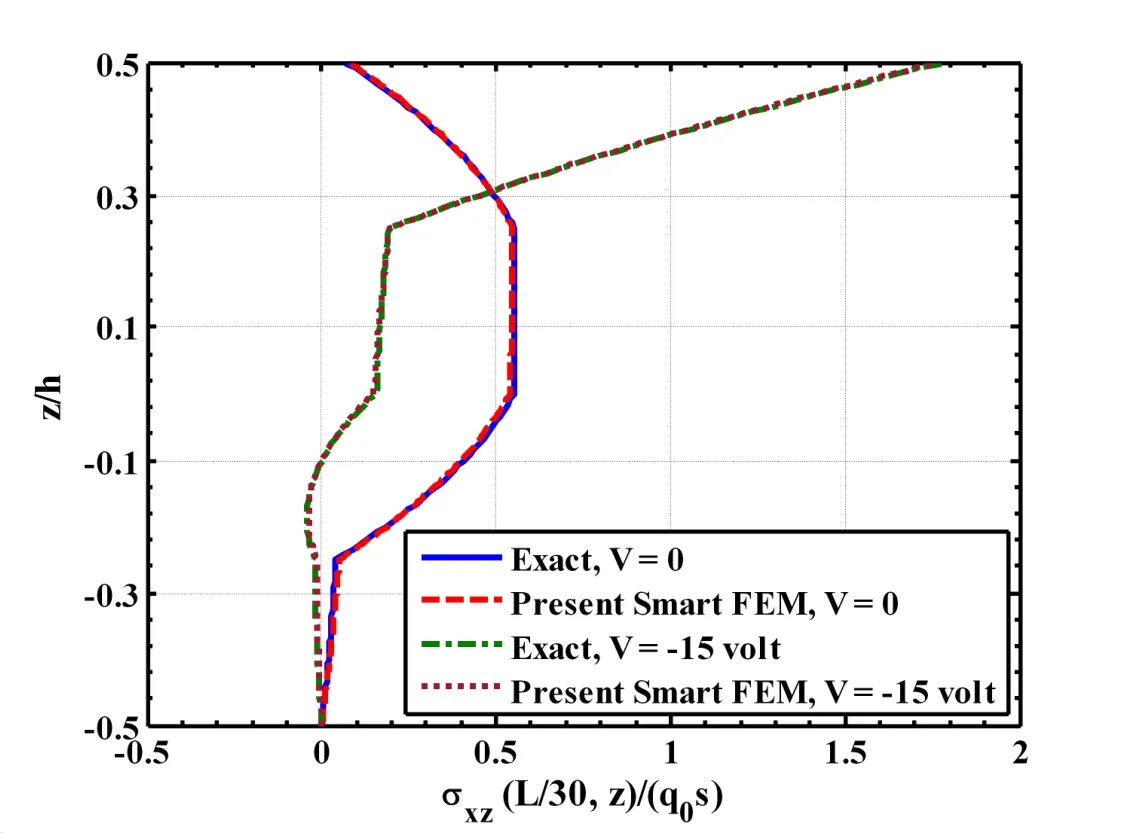
Figure 13:Distribution of the transverse shear stress across the thickness of the four layered(0˚/90˚/0˚/90˚)composite beam(L/h=50,hp=250µm,h=0.005m,q0=50N/m2).
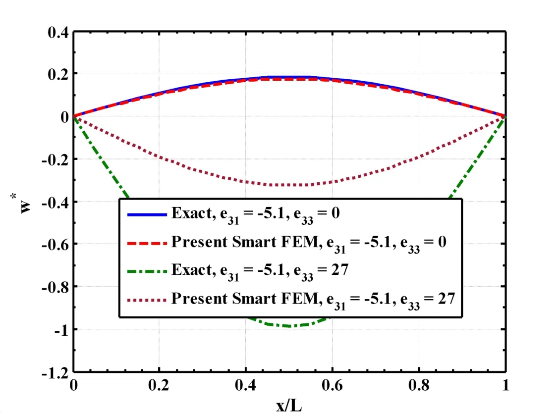
Figure 14:Comparisons of the responses due to in-plane actuation(e31/=0,e33=0)and combined in-plane and transverse actuations(e31/=0,e33/=0)with those obtained by the exact solutions considering one element across the thickness of the overall single layered substrate composite beam(L/h=50,hp=250µm,h=0.005m,
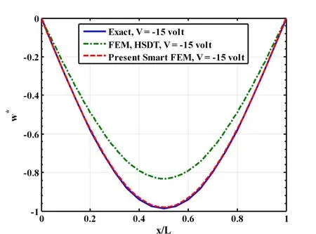
Figure 15:Comparison of the FEM based on the HSDT with the present smart FEM for active shape control of a single layered substrate composite beam(L/h=50,hp=250µm,h=0.005m,
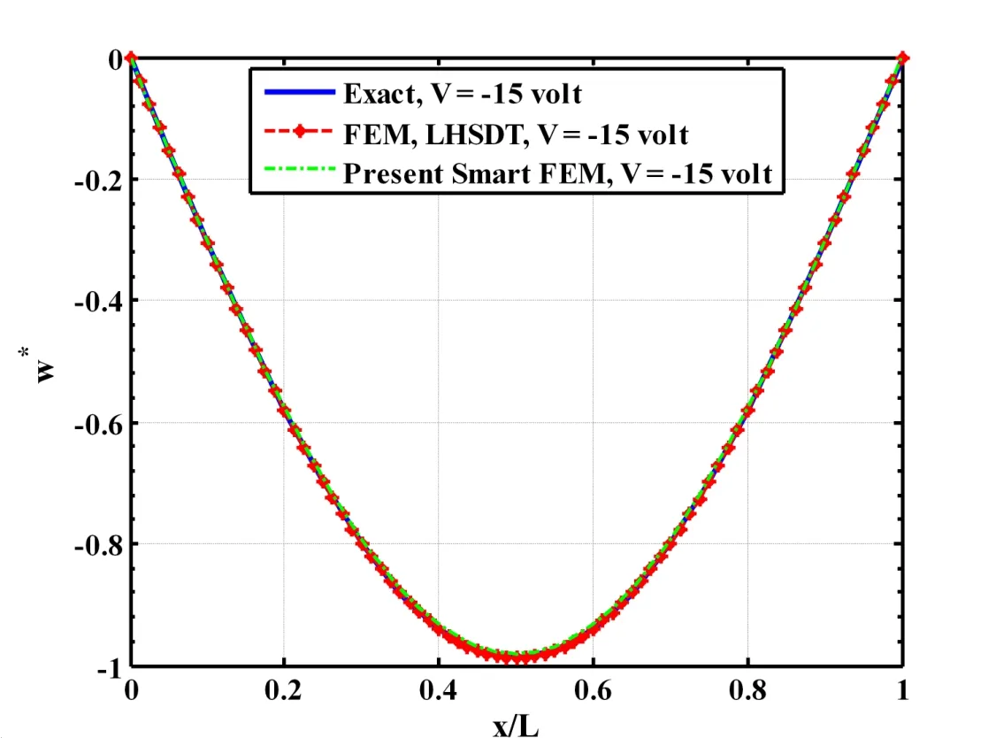
Figure 16:Comparison of the FEM based on the LHSDT with the present smart FEM for the active shape control of a single layered substrate composite beam(L/h=50,hp=250µm,h=0.005m,q0=50N/m2,
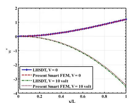
Figure 17:Active shape control of single layered cantilever substrate composite beam(L/h=50,hp=250µm,h=0.005m,q0=50N/m2,
At this juncture it may be recalled that the forgoing results are presented considering one element across the thickness of the substrate beam and one piezoelectric finite element across the thickness of the piezoelectric layer as shown in Fig.2(a).Thus two elements are used across the thickness of the overall smart beam.Since the beam element contains multiple orthotropic layers,a question naturally arises that if one element can be used across the thickness of the overall smart beam in which the top layer of the element is the piezoelectric layer as shown in Fig.2(b).Figure 14 illustrates such results for the deflection of the mid-plane of a single-layered substrate beam when one element is used across the thickness of the overall beam.It may also be noted that whene31/=0 ande33=0,the piezoelectric layer causes in-plane actuation.On the other hand whene31/=0 ande33/=0,the piezoelectric layer causes both in-plane and transverse actuations simultaneously.Also,if the magnitude ofe33is much larger than that ofe31,the transverse actuation by the piezoelectric layer will be predominant must be modeled.It may be observed from Fig.14 that if the piezoelectric layer acts as the in-plane actuator,the responses obtained by the present smartFEMwith one element across the thickness of the overall beam excellently match with the exact solutions.If both in-plane and transverse actuations by the piezoelectric layer are modeled by using one element across the thickness of the overall beam,the responses of the actuated substrate beam do not match with the exact solutions.This may be attributed to the fact that the transverse displacement continuity at the interface between the piezoelectric layer and the substrate beam cannot be explicitly satisfied using one element across the thickness.But it may again be observed from Fig.4 that if one element for the substrate beam and one piezoelectric finite element for the piezoelectric layer are used across the thickness of the overall beam,the responses due to transverse actuation computed by the present newFEMexcellently match with the exact solutions.In order to be confirmed that a separate piezoelectric finite element is necessary across the thickness of the overall beam for the piezoelectric material characterized with large value ofe33,the responses of the overall beam obtained by the different finite element models based on an equivalent single layer high order shear deformation theory(HSDT)and a layer-wise high order shear deformation theory(LHSDT)as derived in Section 3.0 are compared with the exact solutions as shown in Figs.15 and 16.For the results obtained by the present new smartFEMas displayed in Figs.15 and 16,two elements are considered across the thickness of the overall beam.It may be observed from Fig.15 that the responses obtained by theFEMbased on an equivalent single layerHSDTdiffer unacceptably from that obtained by the present new smartFEMand exact solutions.But the responses obtained by theFEMbased on theLHSDTexcellently match with that obtained by the present new smartFEMand exact solutions as shown in Fig.16.This ensures that at least two elements comprising one element for the substrate beam and one element for the piezoelectric layer across the thickness of the overall smart beam must be considered for deriving accurateFEMbased on the proposed new method.Also,for the results presented in Fig.16,the new smartFEMrequires 66 degrees of freedom for the beam,whereas theFEMbased of theLHSDTrequires 492 degrees of freedom.Thus the present new smartFEMis computationally much less costly than theFEMbased on theLHSDT.Similar results are also obtained for the substrate cross-ply beams with more number of laminae.However,for the sake of brevity they are not presented here.Finally,the deflections of a cantilever smart beam subjected to uniformly distributed load with intensityq0=50N/m2and actuated by the piezoelectric layer are presented in Fig.17.In this case,the piezoelectric layer is subjected to a uniformly distributed applied electric potential at its top surface.It may be observed from this figure that the responses obtained by the present newFEMmatch excellently with that obtained by theFEMbased on theLHSDT.Thus the present new 4-noded smart finite element can be efficiently used for accurate modeling of the smart composite beams without using the existing higher-order deformation theories or layer-wise deformation theories.
6 Conclusions
In this paper,new smart finite elements have been developed for the static analysis of smart laminated composite beams.The smart beam is composed of a laminated substrate composite beam integrated with a piezoelectric layer at its top surface which acts as the distributed actuator of the substrate beam.In case of simply supported beams,the top surface of the piezoelectric layer is subjected to the sinusoidally distributed mechanical load and a sinusoidally distributed applied electric potential.In case of the cantilever beam,the top surface of the piezoelectric layer is subjected to the uniformly distributed mechanical load and electrical potential.For the simply supported smart composite beams,exact solutions are derived to validate the proposed new smart finite elements.These smart beams are also modeled for comparison purpose by the conventional finite element method using an“equivalent high order shear deformation theory(HSDT)”and a “layer-wise high order shear deformation theory(LHSDT)”.Several examples are considered for presenting the numerical results.Two types of new smart finite elements are developed.One is purely piezoelectric called the “piezoelectric element”and is used to discretize the piezoelectric layer.The other element is a “laminated smart element”in which the top layer is piezoelectric,while the other layers are the orthotropic layers of the substrate beam.The overall smart composite beam has been discretized by using either two elements or one element across the thickness of the beam.In case of two elements across the thickness,the top element is the“piezoelectric f inite element”and the bottom element is the “laminated beam element”containing only the orthotropic layers of the substrate beam.When the piezoelectric actuator layer is active and passive,and causes both transverse and in-plane actuations,the deflections,bending stresses and the transverse shear stresses of the smart composite beams computed by the present new smartFEMexcellently match with those obtained by the exact solutions if two elements are used across the thickness of the overall beams.If one laminated smart finite element is used across the thickness of the overall smart composite beams,the transverse actuation by the piezoelectric layer cannot be accurately modeled.The transverse actuation by the piezoelectric layer cannot be accurately modeled even if the overall smart beam is modeled by using the equivalent single layerHSDT.When the overall smart beam is modeled by using theLHSDT,the responses of the smart composite beams due to both transverse and in-plane actuations by the piezoelectric layer excellently match with those obtained by the exact solutions and the new smartFEMconsidering two elements across the thickness of the beams.This corroborates the fact that in case of the piezoelectric actuator that is characterized by the large value of the transverse piezoelectric coefficient(e)33at least one piezoelectric finite element and one beam element must be used across the thickness of the overall smart beams for accurate finite element modeling of the smart composite beams.The new smartFEMderived here also accurately computes the active and passive responses of the cantilever smart composite beams.As compared to the otherFEMs based on theHSDTand theLHSDT,the effort needed to derive the present new 4-noded smartFEMis negligible.Also,the present new smartFEMis computationally significantly less costly than theFEMs derived by using theHSDTand theLHSDT.The investigations carried out here suggests that the present new 4-noded smart finite element can be efficiently used for accurate modeling of smart composite beams without using the explicit forms of the displacement fields such as the classical beam theory,the first order and the high order shear deformation theories,the layer-wise theory and the like.
Ahmad,S.N.;Upadhyay,C.S.;Venkatesan,C.(2005):Electroelastic analysis and layer-by-layer modeling of a smart beam.AIAA Journal,vol.43,no.12,pp.2606-2612.
Al-Ajmi,M.A.;Benjeddou,A.(2008):Damage indication in smart structures using modal effective electromechanical coupling coefficients.Smart Materials and Structures,vol.17,art no.035023.
Bailey,T.;Hubbard,J.E.(1985):Distributed piezoelectric polymer active vibration control of a cantilever beam.AIAA Journal of Guidance and Control,vol.8,no.5,pp.605-611.
Bruke,S.E.;Hubbard,J.E.(1987):Active vibration control of a simply supported beam using a spatially distributed actuator.IEEE Control System Magazine,vol.8,pp.25-30.
Bhattacharyya,P.;Suhail,H.;Sinha,P.K.(1998):Finite element free vibration analysis of smart laminated composite beams and plates.Journal of Intelligent Material Systems and Structures,vol.9,pp.20-32.
Bendary,I.M.;Elshafei,M.A.;Riad,A.M.(2010):Finite element model of s-mart beams with distributed piezoelectric actuators.Journal of Intelligent Material Systems and Structures,vol.21,pp.747-754.
Crawley,E.F.;Luis,J.D.(1987):Use of piezoelectric actuators as elements of intelligent structures.AIAA Journal,vol.27,pp.1801-1807.
Chee,C.Y.K.;Tong,L.;Steven,G.(1999):A mixed model for composite beams with piezoelectric actuators and sensors.Smart Materials and Structures,vol.8,pp.417-432.
Chee,C.;Tong,L.;Steven,G.P.(2002):Piezoelectric actuator orientation optimization for static shape control of composite plates.Composite Structures,vol.55,pp.169-184.
Dong,L.;Atluri,S.N.(2011):A Simple Procedure to Develop Efficient&Stable Hybrid/Mixed Elements,and Voronoi Cell Finite Elements for Macro-&Micromechanics.Computers,Materials&Continuum,vol.24,no.1,pp.61-104.
Dong,L.;EI-Gizawy,A.S.;Juhany,K.A.;Atluri,S.N.(2014):A simple locking-alleviated 4-node mixed-collocation finite element with over-integration,for homogenous or functionally-graded or thick-section laminated composite beams.Computers,Materials&Continuum,vol.40,no.1,pp.49-77.
Elshafei,M.A.;Alraiess,F.(2013):Modeling and analysis of smart piezoelectric beams using simple higher order shear deformation theory.Smart Materials and Structures,vol.22,art no.035006.
Forward,R.L.(1981):Electronic damping of orthogonal bending modes in a cylindrical mast-experimen.Journal of Spacecraft and Rocket,vol.18,no.1,pp.11-17.
Gupta,V.K.;Seshu,P.;Issac,K.K.(2004):Finite element and experimental investigation of piezoelectric actuated smart shells.AIAA Journal,vol.42,pp.2112-2118.
Ha,S.K.;Keilers,C.;Chang,F.K.(1992):Finite element analysis of composite structurescontainingdistributedpiezoceramicsensorsandactuators.AIAA journal,vol.30,no.3,pp.772-780.
Hwang,W.S.;Park,C.H.(1993):Finite element modeling of piezoelectric sensors and actuators.AIAA journal,vol.31,no.5,pp.930-936.
Im,S.;Atluri,S.N.(1989):Effects of piezoactuator on a finitely deformed beam subjected to general loading.AIAA Journal,vol.25,pp.1373-1385.
Kulkarni,S.A.;Bajoria,K.M.(2003):Finite element modeling of smart plates/shells using higher order shear deformation theory.Composite Structures,vol.62,pp.41-50.
Lo,K.H.;Christensen,R.M.;Wu,E.M.(1978):Stress solution determination for high order plate theory.International Journal of Solids and Structures,vol.14,pp.655-662.
Lin,C.;Hsu,C.;Huang,H.N.(1996):Finite element analysis on deflection control of plates with piezoelectric actuators.Composite Structures,vol.35,pp.423-433.
Luo,Q.;Tong,L.(2004):An accurate laminated element for piezoelectric smart beams including peel stress.Computational Mechanics,vol.33,pp.108-120.
Miller,S.E.;Hubbard,J.E.(1987):Obsevability of a Bernouli-Euler beam using PVF2as a distributed sensor.MIT Draper Laboratory Report.
Neto,M.A.;Yu,W.;Roy,S.(2009):Two finite elements for general composite beams with piezoelectric actuators and sensors.Finite Elements in Analysis and Design,vol.45,pp.295-304.
Pagano,N.J.(1970):Exact solutions for rectangular bidirectional composites and sandwich plates.Journal of Composite Materials,vol.4,pp.20-34.
Park,H.;Lee,U.(2012):Dynamic analysis of smart composite beams by using the frequency-domain spectral elemental method.Journal of Mechanical Science and Technology,vol.26,pp.2511-2521.
Robbins,D.H.;Reddy,J.N.(1991):Analysis of piezoelectrically actuated beams using a layer-wise displacement theory.Computers&Structures,vol.41,no.2,pp.265-279.
Ray,M.C.;Bhattacharyya,R.;Samanta,B.(1994):Static analysis of an intelligent structure by the finite element method.Computers and Structures,vol.52,no.4,pp.617-631.
Shi,G.;Atluri,S.N.(1990):Active control of nonlinear dynamic response of space-frames using piezo-electric actuators.Computers and Structures,vol.34,no.4,pp.549-564.
Smith,W.A.;Auld,B.A.(1991):Modeling 1-3 composite piezoelectrics:Thickness mode oscillations.IEEE Transactions on Ultrasonics,Ferroelectrics and Frequency Control,vol.31,pp.40–47.
Saravanos,D.A.;Heyliger,P.R.(1995):Coupled layerwise analysis of composite beams with embedded piezoelectric sensors and actuators.Journal of Intelligent Material Systems and Structures,vol.6,pp.350-362.
Saravanos,D.A.;Hetliger,P.R.;Hopkins,D.A.(1997):Layerwise mechanics and finite element for the dynamic analysis of piezoelectric composite plates.International Journal of Solids and Structures,vol.34,no.3,pp.359-378.
Song,Y.;Kim,S.;Park,I.;Lee,U.(2015):Dynamics of two-layer smart composite Timoshenko beams:frequency domain spectral element analysis.Thin-Walled Structures,vol.89,pp.84-92.
Trindade,M.A.;Benjeddou,A.(2006):On higher-order modeling of smart beams with embedded shear-mode piezoceramic actuators and sensors.Mechanics of Advanced Materials and Structures,vol.13,pp.357-369.
Umesh,K.;Ganguli,R.(2011):Composite material and piezoelectric coefficient uncertainty effects on structural health monitoring using feedback control gains as damage indicators.Structural Health Monitoring,vol.10,no.2,pp.115-129.
Varadarajan,S.;Chandrashekhara,K.;Agarwal,S.(2000):LQG/LTR-based robust control of composite beams with piezoelectric devices.Journal of Vibration and Control,vol.6,pp.607-630.
Valoor,M.T.;Chandrashekhara,K.;Agrawal,S.(2001):Self-adaptive vibration control of smart composite beams using recurrent neural architecture.International Journal of Solids and Structures,vol.38,pp.7857-7874.
Zabihollah,A.;Sedagahti,R.;Ganesan,R.(2007):Active vibration suppression of smart laminated beams using layerwise theory and an optimal control strategy.Smart Materials and Structures,vol.16,pp.2190-2201.
Zhang,S.Q.;Schmidt,R.(2014):Static and dynamic FE analysis of piezoelectric integrated thin-walled composite structures with large rotations.Composite Structures,vol.112,pp.345-357.
Appendix
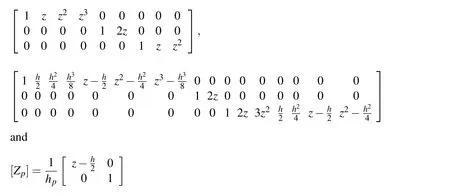
The matrices[Z1],[Z2]and[Zp]appearing in Eqs.(67)and(70)are as follows:
The nodal strain-displacement matrices[B1]and[B2]are given by[B1]=?[B11] [B12][B13]?and[B2]=?[B21][B22][B23]?
The nonzero elements of the submatrices[B1i],i=1,2,3 are as follows:

B1i(5,9)=B1i(6,10)=B1i(7,3)=ni, B1i(8,4)=2niand B1i(9,5)=3ni
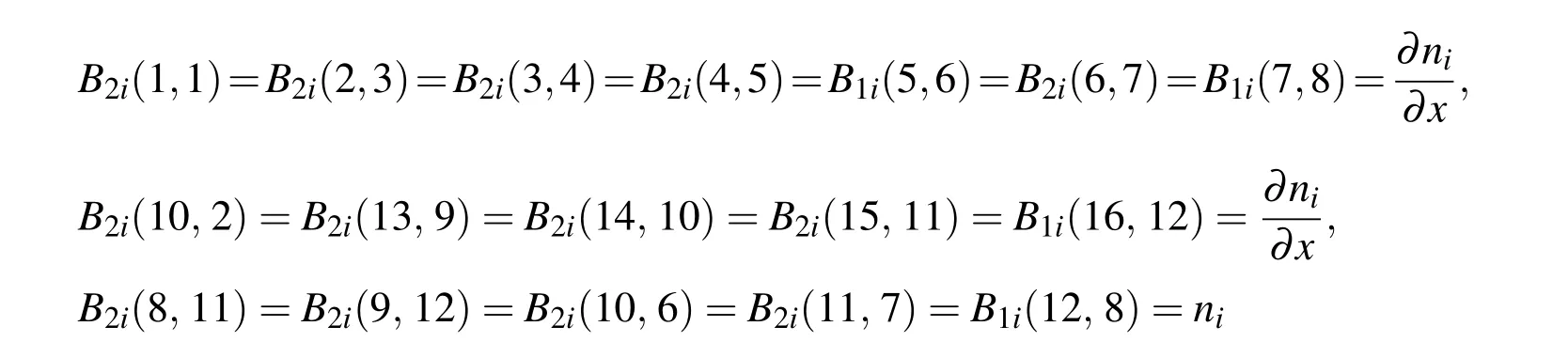
The nonzero elements of the submatrices[B2i],i=1,2,3 are as follows:
The nodal electric field-potential matrix[B3]appearing in Eq.(70)is given by
1Department of Mechanical Engineering,Indian Institute of Technology,Kharagpur,India.
2Corresponding Author,School of Aeronautic Science and Engineering,Beihang University,China.Email:dong.leiting@gmail.com.
3Department of Mechanical Engineering,Texas Tech University,USA
 Computer Modeling In Engineering&Sciences2016年5期
- Computer Modeling In Engineering&Sciences的其它文章
- Analysis and Numerical Simulation for Tunnelling Through Coal Seam Assisted by Water Jet
- The Numerical Accuracy Analysis of Asymptotic Homogenization Method and Multiscale Finite Element Method for Periodic Composite Materials
- A Homogenized Function to Recover Wave Source by Solving a Small Scale Linear System of Differencing Equations