
Energy saving by using asymmetric aftbodies for merchant ships-design methodology, numerical simulation and validation*
2016-12-26 06:51JieDANGHaoCHEN陈灏
水动力学研究与进展 B辑 2016年6期
Jie DANG, Hao CHEN (陈灏)
1. Maritime Research Institute Netherlands (MARIN), Wageningen, The Netherlands, E-mail: J.Dang@marin.nl
2. Guangzhou Shipyard International Company Ltd., Guangzhou 510382, China
Energy saving by using asymmetric aftbodies for merchant ships-design methodology, numerical simulation and validation*
Jie DANG1, Hao CHEN (陈灏)2
1. Maritime Research Institute Netherlands (MARIN), Wageningen, The Netherlands, E-mail: J.Dang@marin.nl
2. Guangzhou Shipyard International Company Ltd., Guangzhou 510382, China
The methodology and procedures are discussed on designing merchant ships to achieve fully-integrated and optimized hull-propulsion systems by using asymmetric aftbodies. Computational fluid dynamics (CFD) has been used to evaluate the powering performance through massive calculations with automatic deformation algorisms for the hull forms and the propeller blades. Comparative model tests of the designs to the optimized symmetric hull forms have been carried out to verify the efficiency gain. More than 6% improvement on the propulsive efficiency of an oil tanker has been measured during the model tests. Dedicated sea-trials show good agreement with the predicted performance from the test results.
energy saving, hull form, asymmetric aftbody, model tests, sea trials
Introduction
Ship design for its powering performance has experienced continuous improvement on both hull forms and propulsors. Hull forms are, in principle, designed to accommodate certain types of propulsors, so that a single screw ship defers from a multiple-screw ship and a ship with azimuthing thrusters or pods differs from a ship with water jet systems, as the examples. Propulsors are tailored for the wake fields generated by the hulls, as so-called the “wake-adapted” propulsor designs[1]. For merchant ships, although cares have been taken in the hull form designs to achieve better wake fields at the propellers for a better cavitation performance and to lead more viscous wake into the propeller discs in order to increase hull efficiency, a real ‘propeller-adapted’ hull form design has not yet been fully developed.
For decades, MARIN has been dedicated at developing sophisticated CFD-aided optimization procedures and tools to design both the hull forms and propeller geometry in order to achieve the fully-integra-ted designs with maximized propulsive efficiency and comfort for ships. It started from the optimization method for the resistance and the wake quality, for the shaft power based on series propellers[2], for the shaft power with actual design propellers by using RANSBEM coupling technique and gradually developed into“fully-integrated” optimization procedures recently, where the hull form and the propeller geometry can be designed simultaneously[3].
The above mentioned techniques have been proven in practice to improve the powering performance of the single screw ships significantly, by both model tests and sea trials.
When a ship with single screw and symmetric hull form is already optimized, the remaining energy losses behind the ship are then mainly the asymmetric slip-stream behind the propeller which rotates in one single direction, and the non-uniform axial flow which has typically a higher speed behind the down-running blades and lower speed behind the up-running blades. The energy losses and the principle of the ship propulsion has been already fully established in Ref.[4] and further elaborated in Ref.[5] with practical considerations. Recent studies have shown that both the transverse kinetic energy loss due to the swirl of the flow and also the axial kinetic energy loss due to the nonuniform axial velocity in the far field, behind the propeller and the rudder, are the two major energy losses that can be recovered by using the Energy SavingDevices (ESDs)[6,7].
As already made clear by studies, ESDs often surfer from scale effects and fouling in full scale. Losing the stator blades of the ESDs, in some cases, and damaging the hull structure with cracks often make the ship owners worried about applying ESDs to their ships. Some ESDs have been cut off after a period of the ships’ life in service due to practical reasons[8-10].
The merit of applying an asymmetric aftbody for a single-screw ship lies in the fact that the swirl and the non-uniform flow of the ship’s wake can be regulated in the same way (or even a better way) as by applying ESDs to improve the propeller-hull interactions, but without adding “additional appendages”onto the hull. This idea is hence reviving in recent years.
Despite of the maneuvering problem of “Carlotti”, studied and tested at MARIN in the early 1950’s that confirmed 15% shaft power savings by applying an asymmetric aftbody[11,12], some container ships with asymmetric aftbodies have been built in the 1980’s[13]and further studies went on into late 1980’s and early 1990’s[14-17]. It could be due to the difficulties in designing and judging the asymmetric aftbodies by using only model tests in the 1980’s, and it could also be due to the difficulties in the ship’s arrangement and construction in full scale, asymmetric aftbodies were not prevailing. In the last decades however, the rapid growth of practical applications of the CFD in hull form and propeller blade designs opened a new era for applying asymmetric aftbodies for ships where a fullyintegrated hull-propeller design could be achieved to minimize the energy losses[18-21].
The present paper will elaborate the design methodology and the optimization procedures, with a focus on the validation of the asymmetric ship designs by using both model tests and also full scale trial data. For the ship used as an example and discussed in this paper, the CFD evaluations of the propulsive performance of the asymmetric aftbody, the resistance and propulsion tests, the cavitation observations and the hull pressure fluctuation measurements, the course stability and maneuvering tests, and the sea trials have all been carried out with a final design propeller at MARIN. More than 6% improvement on the total propulsive efficiency for this ship with an asymmetric aftbody, with respect to an optimized symmetric ship, has been found at the design draught by model tests. The sea trial data show also a good agreement with the prediction from the model test results.
1. Calculations
1.1 Fully-integrated design and massive CFD calculations
The RANS code-PARNASSOS, a code developed and frequently applied by MARIN, was used to calculate the flow along the hull. It predicts the steady turbulent flow around the ship hulls and solves the discretised Reynolds-averaged Navier-Stokes (RANS) equations for steady incompressible flow. Turbulence models are implemented in the code. Structured multi-block grids are used with a finite-difference discretization of second and third-order schemes for the various terms.
This RANS code is coupled with a code based on Boundary Element Method (BEM) for potential flow simulation of propellers with blade sheet cavitationcalled PROCAL, developed under the framework of the Cooperative Research Ships (CRS). The coupling is done iteratively between the propeller loads and the volume forces for the RANS, until a self-propulsion balance has been found at a given shaft power or a given speed. This technique is called RANS-BEM coupling.
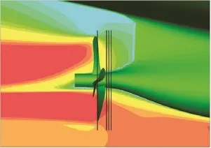
Fig.1(a) Planes defined in front of the propeller for the extrapolation of the effective wake to the propeller plane. Plane No. 0 is at propeller plane, Plane Nos. 1, 2 and 3 are located at a distance x/ R=0.20, 0.25 and 0.30 in front of the propeller, respectively[9]
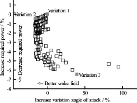
Fig.1(b) The Pareto front of a 78 000 DWT bulk carrier, as an example[8]
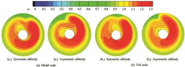
Fig.2 Comparisons of the total velocity field behind an operating propeller in model and full scales, for ships with symmetric and asymmetric aftbodies[8]
The merit of this technique is that the induced velocity of the propeller can be calculated from the BEM code and subtracted from the total velocity field of the RANS calculations so that the effective wake field can be obtained, as shown in Fig.1(a). An effective wake field is essentially important for the propeller design.
With thousands of hull form and propeller geometry combinations, a huge matrix of variations can be prepared for the analysis. CPU and memory requirements of the PARNASSOS are quite modest compared to most other commercial codes. The BEM calculations consumes negligible amount of CPU time, even if with cavitation simulations. However, for the hundreds of thousands of variations of hull forms and propellers, parallel computations are needed. At MARIN, the massive computations for all variants can be done at the computer cluster with 4 000 computational cores or distributed over a large number of idle PCs at night, using the Condor tools. Typically, more than thousands of variants can be calculated over one night.
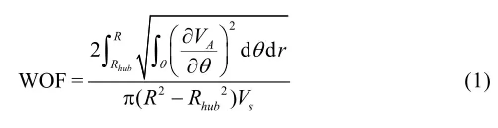
To judge the performance of the variants, various objective functions can be defined. For the power, either the resistance (the effective power) or the propeller shaft power of the ship can be used. For the comfort, either the pressure fluctuations/induced excitations or the uniformity of the nominal/effective wake (change of angle of attacks to the section profile of the propeller blades) can be used, where a wake objective function (WOF) is often defined as,
The best compromise of the efficiency and comfort can be found at a Pareto front. As an example shown in Fig.1(b), the relative changes on the shaft power and the quality of the effective wake field are used. Based on the Pareto front, an optimized hull form and propeller geometry can be determined. For a fullyintegrated full-propeller design, the Pareto front is often based on the shaft power against the vertical excitation force of the cavitating propeller.
More details of the optimization using automatic deformation of the hull and propeller geometry, the massive calculations and the numerical settings can be found in Refs.[8], [9] and [22].
1.2 Wake field and kinetic energy
Although the shaft power can be calculated directly by the RANS-BEM coupling technique and assessed for the ship’s powering performance, the kinetic energy losses in the ship’s far wake field, where the static pressure is completely recovered, provide indirect but easy assessment on the propulsive efficiency gain and are better illustrations of the velocity fields. The complete theory can be found in Ref.[4], however the kinetic energy losses in the wake can be simplified into Eqs.(2) to (4) below,
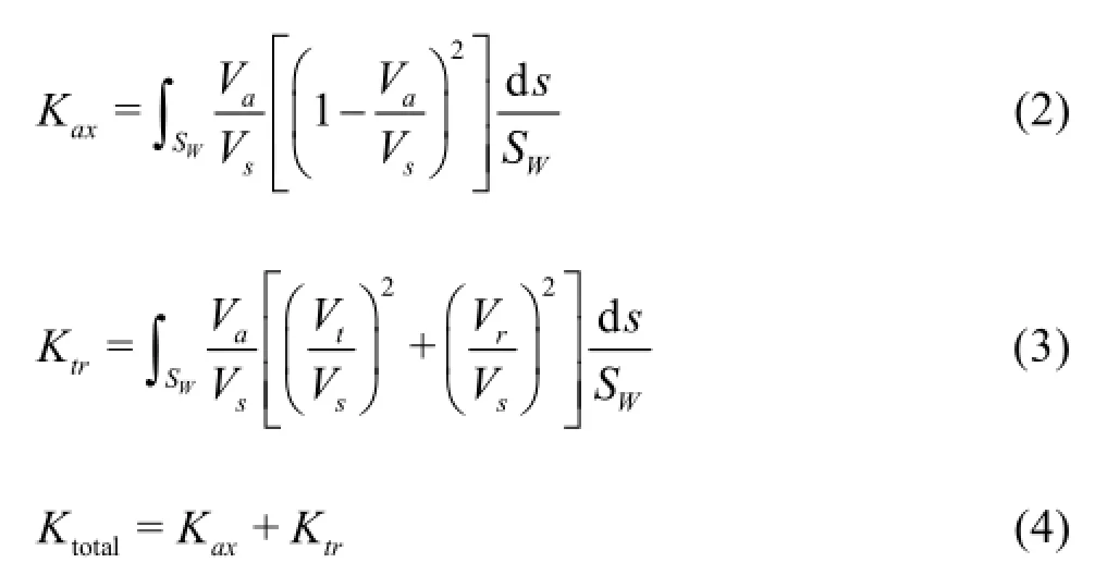
where the total kinetic energy losses are split into the axial part Kaxand the transverse part Ktr.
It might be not a bad idea to make an assessment of the kinetic energy losses just behind the propeller, as shown by the “behind wake disc” in Fig.10 of Ref.[8], instead of the real far field where numericaldissipation may become too strong. Although the static pressure just behind the propeller is not completely recovered, it is assumed that the difference between the symmetric hull and the asymmetric hull may not differ too much. The kinetic energy difference at that location may provide important information on the energy saving by applying an asymmetric aftbody in a relative sense.
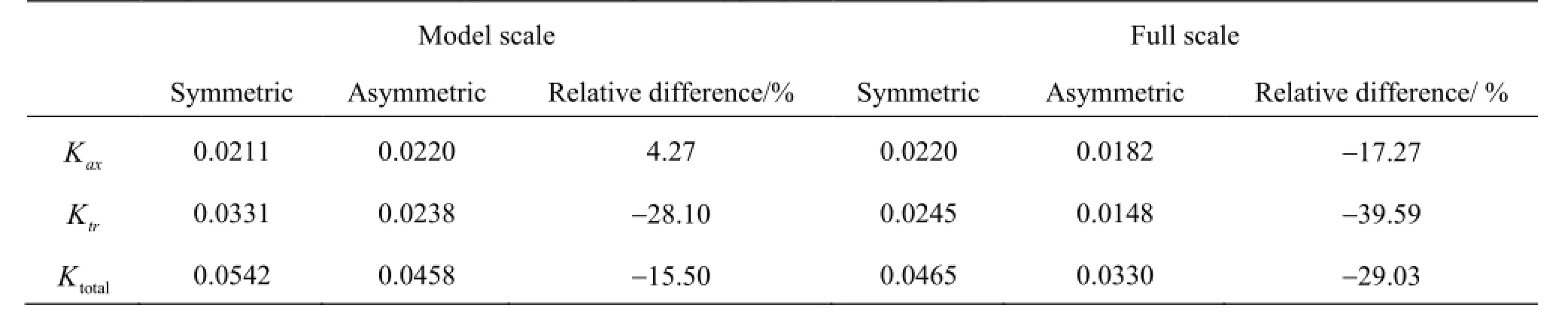
Table 1 Comparison of kinetic energy behind an operating propeller at self-propulsion condition[8]
On the “behind wake disc” with a propeller in operation at the self-propulsion condition, the velocity wake fields are compared to each other in Fig.2, between the symmetric and the asymmetric aftbodies for both the model scale and the full scale.

Fig.3(a) The large scale ship model with asymmetric aftbody with the rudder and the final design propeller
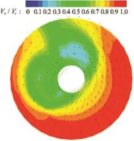
Fig.3(b) The measured nominal wake field at the propeller disc in model scale[9]
It can be seen from the wake field that: compared to the symmetric aftbody, the axial velocity field becomes more uniform for the asymmetric aftbody, especially the reduction of the peak on the starboard side where the propeller blades rotate downwards; on the portside, the tangential velocity is reduced significantly by the asymmetric aftbody. When using Eqs.(2) to (4), the kinetic energy losses can be quantified in a relative sense in Table 1.
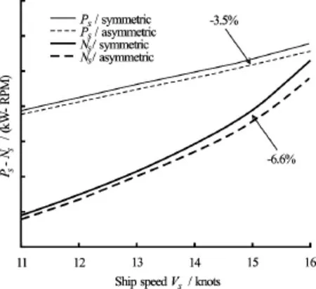
Fig.4(a) Shaft power savings and shaft rotational rate changes due to asymmetric aftbody (at design draught)
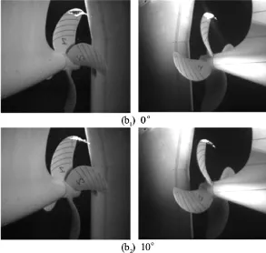
Fig.4(b) Screen shots of the high speed underwater video’s of the cavitation observation at design draught and speed of the ship[8]
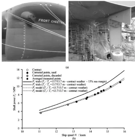
Fig.5 MV Front Cheetah, the asymmetric aftbody in building and the sea trial results compared to the model test results
It is clearly seen that the total reductions of the kinetic energy losses is about 15.5% in model scale and about 29.0% in full scale by the asymmetric aftbody, in the domain studied. The reduction of the kinetic energy in full scale doubles almost that in model scale. This may indicate more energy saving in full scale than in model scale by asymmetric aftbodies, as already experienced in full scale trials by Ref.[12].
2. Model tests
Ship models for both powering and maneuvering tests of the performance have been manufactured with the asymmetric aftbodies, as shown in Figs.3(a) and 3(b), in order to verify both efficiency gain and course stability of the ship for which people worried. The measured nominal wake filed is shown also in this figure where the pre-swirl against the rotation of the propeller and the reduced axial flow on the port side are clearly seen.
It is rather similar to the test results of other asymmetric ships developed in the 1980’s[11,12]that slightly lower resistance has been measured in various draughts for the present ship with an asymmetric aftbody. Although it cannot be generalized that an asymmetric aftbody can reduce the ships resistance, both the kinetic energy analyses and the resistance tests show that an asymmetric aftbody has limited effect on the ship’s resistance if designed properly.
By assuming that the amount of viscous wake, which goes through the propeller disc, is the same for the symmetric and asymmetric aftbodies, the same wake scaling can be used in the extrapolation of the self-propulsion test results. The speed-power-RPM relations are obtained and plotted in Fig.4(a) on the lefthand side for the design draught compared to the ship with the symmetric aftbody. A 6.6% shaft power saving has been found by the asymmetric aftbody. In addition, stable sheet cavitations have been observed and low pressure fluctuations on the hull surface have been measured, see the photos in Fig.4(b) on the righthand side.
3. Sea trials
A series of oil tankers discussed above have beenbuilt at Guangzhou Shipyard International Company Ltd. (GSI). Dedicated sea trials have been carried out by MARIN’s Trials and Monitoring Department, including speed-power trials and also manoeuvring trials.
As the first ship of the series, the speed power trials have been performed on board MV Front Cheetah in January (see Fig.5), 2016 in the South China Sea, south of Guangzhou. The analysis of the measurements and the corrections to arrive at the specified contract conditions are done according to the STAIMO speed trial analysis protocols. The speed trial results are analysed using STAIMO V2.2, following ISO (2015).
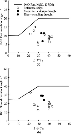
Fig.6 Comparison of the maneuvering trial results to the model test results
The speed trials have been conducted in the ballast, design and scantling loading conditions. The ship speed, course, heading and position were measured by a Hemisphere twin DGPS. The DGPS antenna was installed on top of the bridge. The delivered propulsion power is determined by the power measurement system (PMS) on the shaft. This system measures with a strain gauge the deflection of the shaft, which is a measure for the torque. An optical sensor records the RPM of the shaft. During the trials, the water depth was around 70 m to 100 m and weather condition was moderate with wave height around 2.2 m to 2.3 m.
The trial results were corrected for wind, wave and current. Water depth and displacement were carefully monitored and corrected too. The trial results, corrected for the ideal trial condition for the design draught, are shown on the right-hand side in Fig.5. The deviation between the trial results and the prediction from the model tests is less than 2%.
Manoeuvring tests were also tried at the same time period. The results are compared to the model test results in Fig.6 and correlated very well with the predictions which confirmed the course stability of the ship.
4. Conclusion
The design methodology and design tools for a fully-integrated ship’s hull form and propeller geometry have been developed at MARIN in the last decades, with emphasis on single screw ships in order to maximize the total propulsive efficiency and comfort gains for merchant ships. The asymmetric aftbodies have been applied and shown promising results for the integration of hull and propeller designs, without adding any appendages such as ESDs. For the ship used as an example in this paper, more than 6% improvement on the total propulsive efficiency has been achieved and measured by model tests which were further verified by full scale trials with good cavitation performance and low vibration levels, alongside the ship’s good course stability.
Acknowledgements
The authors are grateful for the valuable support from Guangzhou Shipbuilding International Company Ltd. (GSI) for the present study. Thanks are also extended to Harry Willemsen, Luis Rueda, Auke van der Ploeg and Geerhard Janse of MARIN for lines and CFD calculations.
[1] Oosterveld M. W. C. Wake adapted ducted propellers [D]. Doctoral Thesis, Delft, The Netherlands: Delft Technical University, 1970.
[2] Van Der Ploeg A., Raven H. C. CFD-based optimization for minimal power and wake field quality [C]. Proceedings of 11th International Symposium on Practical Design of Ships and Other Floating Structures (PRADS). Rio de Janeiro, Brazil, 2010.
[3] Van Der Ploeg A., Foeth E.-J. Optimization of a chemical tanker and propeller with CFD [C]. Proceedings of ECCOMAS International Conference on Computational Methods in Marine Engineering V. Hamburg, Germany, 2013.
[4] Wald Q. Performance of a propeller in a wake and the interaction of propeller and hull [J]. Journal of Ship Research, 1965, 9: 1-8, 36.
[5] Dyne G. The principles of propulsion optimization [J]. Transactions RINA, 1995, 137: 189-208.
[6] Dang J., Chen H., Dong G. et al. An exploratory study on the working principles of energy saving devices (ESDs) [C]. Greenship’2011. Wuxi, China, 2011.
[7] Dang J., Dong G., Chen H. An exploratory study on the working principles of energy saving devices (ESDs)-PIV, CFD investigations and ESD design guidelines [C]. The 31st International Conference on Ocean, Offshore and Arctic Engineering (OMAE 2012). 2012, paper No. OMAE2012-83053.
[8] Dang J., Chen H., Rueda L. et al. Integrated design of asymmetric aftbody and propeller for an aframax tanker to maximize energy efficiency [C]. SMP’15. Austin, Texas, USA, 2015.
[9] Rueda L., Dang J. Integrated design of asymmetric aftbody and propeller to maximize energy efficiency [C]. Proceedings of Energy Efficient Ships of the Royal Institution of Naval Architects (RINA Conference). Rotterdam, The Netherlands, 2015.
[10] Abramowski T., Żelazny K., Szelangiewicz T. Numerical analysis of effect of asymmetric stern of ship on its screw propeller efficiency [J]. Polish Marine Research, 2010, 15(4): 13-16.
[11] Collatz G. Fuel saving by asymmetric afterbodies for single screw vessels [J]. Ocean Engineering, 1983, 10(4): 213-226.
[12] Collatz G. Non-symmetrical aft-bodies [C]. Proceedings of Workshop on Developments in Hull Form Design. Wageningen, The Netherland, 1985.
[13] Stierman E. J., Osborne M. G. A review of the performance and application of the asymmetric stern [R]. Shell International Marine, SIM Report No. MR 13/86, 1986.
[14] Stierman E. J. The design of an energy saving, wake adapted duct [C]. Proceedings of International Symposium on Practical Design of Ship and Other Floating Structures (PRADS’87). Trondheim, Norway, 1987.
[15] Stierman E. J. Energy saving with an asymmetric stern and wake adapted ducts [C]. Proceedings of International Symposium on Ship Resistance and Powering Performance. Shanghai, China, 1986, 124-132.
[16] Piskorz-Nalecki J. W. The influence of the asymmetric afterbody and the horizontal fins on the rudder blade on the propulsive efficiency [C]. Proceedings of Workshop on Developments in Hull Form Design. Wageningen, The Netherlands, 1985.
[17] Blaurock J. An appraisal of unconventional aftbody configurations and propulsion devices [J]. Marine Technology, 1990, 27(6): 325-336.
[18] Vaz G., Bosschers J. Modelling three dimensional sheet cavitation on marine propellers using a boundary element method [C]. Sixth International Symposium on Cavitation CAV2006. Wageningen, The Netherlands, 2006.
[19] Bosschers J., Vaz G., Starke B. et al. Computational analysis of propeller sheet cavitation and propeller-ship interaction [C]. RINA conference “MARINE CFD2008”. Southampton, UK, 2008.
[20] Starke B., Bosschers J. Analysis of scale effects in ship powering performance using a hybrid RANS-BEM approach [C]. 29th Symposium on Naval Hydrodynamics. Gothenburg, Sweden, 2012.
[21] Rijpkema D., Starke B., Bosschers J. Numerical simulation of propeller-hull interaction and determination of the effective wake field using a hybrid RANS-BEM approach [C]. SMP’13. Launceston, Tasmania, Australia, 2015.
[22] Veldhuis C., Gornicz T. and Scholcz T. Ship optimization using viscous flow computations in combination with generic shape variations and design of experiments [C]. Proceedings of PRADS 2016. Copenhagen, Denmark, 2016.
(Received June 20, 2016, Revised August 13, 2016)
* Biography:Jie DANG, Male, Ph. D., Senior Project Manager
Hao CHEN,
E-mail:chenhao@chinagsi.com

- 水动力学研究与进展 B辑的其它文章
- Development of an adaptive Kalman filter-based storm tide forecasting model*
- Development of Cartesian grid method for simulation of violent ship-wave interactions*
- Numerical study on the effects of progressive gravity waves on turbulence*
- Experimental tomographic methods for analysing flow dynamics of gas-oilwater flows in horizontal pipeline*
- Coupling of the flow field and the purification efficiency in root system region of ecological floating bed under different hydrodynamic conditions*
- Modelling hydrodynamic processes in tidal stream energy extraction*