
Non-Overlapping Conditions to Enable Multi-Dimensional Behavioral Models/DPDs for Multi-Band or Non-Continuous Carrier Aggregation Systems
2017-05-08 01:46CuipingYuZiyuanZhangBeijingKeyLaboratoryofWorkSafetyIntelligentMonitoringBeijing100876China
China Communications 2017年2期
Cuiping Yu, Ziyuan Zhang Beijing Key Laboratory of Work Safety Intelligent Monitoring, Beijing 100876, China
2 School of Electronic Engineering, Beijing University of Posts and Telecommunications, Beijing 100876, China
* The corresponding author, e-mail: yucuiping@bupt.edu.cn
I. INTRODUCTION
For future generations of wireless communication systems, signals such as Multi-Carrier Wideband Code Division Multiple Access(MC-WCDMA) and Orthogonal Frequency Division Multiplexing (OFDM) and Carrier Aggregation (CA) for Long-Term Evolution–Advanced (LTE-A), have been commonly used in order to achieve high data-rate transmission and good spectral efficiency [1]. These signals have the characteristic of wide bandwidths and high peak-to-average power ratios (PAPRs), and bring numerous challenges to the design of power amplifiers (PAs) in regard to linearity. The varying envelope signals of these techniques generate in-band distortions and spectral regrowth in the adjacent channels when amplified by nonlinear radio frequency(RF) PAs[2]. Therefore, several linearization techniques are employed to linearize the RF PAs/transmitters. Among them, digital predistortion (DPD) is one of the most popular.
With the rapid development of multi-band/multi-standard wireless communication systems, new transmitter’s design architectures allow for different communication signals to be transmitted on different frequency bands simultaneously. Novel designs of concurrent dual-band[3-7], multiband [8] and broadband[9-11] RF components have been proposed to support the transmission of signals in different RF bands concurrently.
For such multi-band PAs/transmitters,conventional DPD techniques for single input and single output (SISO) systems are no longer applicable due to the unrealistic sampling rate required to cover a large range of frequencies. Thus, multi-dimensional behavioral models/DPDs have been proposed to deal with this problem. S.A.Bassam et al.proposed 2-D-DPD structures in [12]. They extended the SISO memory polynomial (MP)formulation to a dual-input digital predistortion model, where each signal is transmitted through a separate communication channel that accounts for the cross-modulation effects of the multiple signals. Then Mayada Younes et al. proposed three-dimensional (3-D) triband DPD for concurrent tri-band power amplifier linearization by replaced the passband input signal with the combined tri-band signal[1-2]. A serial of multi-dimensional behavioral models have been proposed to decrease the complexity and improve the accuracy [13-22]. In all these multi-dimensional behavioral models/DPDs, it is assumed that if the frequency spacing between the two/three bands is wide enough, then the harmonic and intermodulation products of carriers’ (HC and IMC) will lie far enough from the interested fundamental bands and can be ignored/ filtered out. In this case, what remains are the signals around the fundamental frequencies, which consist of the amplified input signal plus the in-band intermodulation and cross-modulation distortion. If these HC and IMC products lie inside the interested fundamental bands, the multi-dimensional behavioral models/DPDs will not linearize the PAs/transmitters properly.
In fact, the frequency spacing is limited by the bandwidth of transmitters, and cannot be infinitely increased. In this paper, the non-overlapping conditions, which can make sure the HC and IMC products lie far enough from the interested fundamental bands, are derived and denoted in the form of closedform expression for dual-band and tri-band multi-dimensional behavioral models/DPDs.
This paper is organized as follows. Section II is the analysis on the theory of multi-dimensional behavioral models/DPDs. The non-overlapping conditions are derived for both dual-band and tri-band signals in section III. A set of experiments, which are measured to validate the non-overlapping conditions,is in Section IV, and a conclusion is drawn in Section V.
II. THE ANALYSIS ON THE THEORY OF MIMO BEHAVIORAL MODELS/DPDS
In the literature, most of multi-dimensional behavioral models for PAs have been developed using one of two strategies: generalization of a SISO model structure to accommodate dual-band signals and pruning of the general
Volterra series formulation. Regardless of
which strategy, the multi-dimensional behavioral model considers only the in-band intermodulation and cross-modulation components of the fundamental bands. The HC&IMC products are not considered due to the unacceptably high complexity. The 3-D DPD model is taken to be an example in the following.As described in [2], if a general structure of a memoryless SISO pass-band model is given by:

where y(t) is the estimated model output, x(t)is the passband input signal, N is the nonlinearity order of the model, and akis the set of model coefficients.
For a tri-band input signal, x(t) is given as Equation(2), where xi(t) (i=1,2,3) are the three input signals centered at the three RF frequencies f1, f2, and f3. The complex envelope of the pass-band signal xi(t) at the angular frequency ωi=2πfiis given as Equation (3).

Then, using the binomial expansion and grouping all the elements that lie around different frequencies, the general pass-band equation for the concurrent tri-band model output can be given as (the notation (t) will be removed hereafter for convenience):


Fig.1 The measured output spectrum
From Equation (4), only the baseband model for the three signals at the fundamental frequencies (ω1, ω2, and ω3) is extracted(the items in the rectangle) to build the 3-D DPD model. The other terms of Equation (4)will be ignored, because they are thought to lie outside the interested fundamental bands and could befiltered out when the frequency spacing is large enough. These omitted terms represent the harmonic and intermodulation products of carriers’.
In practical, the frequency spacing is limited by the bandwidth of transmitters, and cannot be infinitely increased. The Fig.1 shows the measured PSD of a tri-band signal amplified by a broad-band PA. The center frequencies of the three bands are ω1=900MHz,ω2=1860MHz and ω3=1920MHz. We can see that the output signal is consists of inband intermodulation products, cross-modulation products, harmonic products of carriers’(HC) and intermodulation products of carriers’(IMC). The amplitude of HC and IMC products (2ω1,2ω3-ω2, ω3-ω1,ω1+ω2-ω3, ω1+ω3-ω2, 2ω2-3ω3…) are as high as inband intermodulation and cross-modulation products, and cannot be ignored when they lies inside the interested fundamental bands.For example, if the bandwidth of the lower band increase to 20MHz, the 5-th order inband intermodulation and cross-modulation products lying in middle band will cover from 1810MHz to 1910 MHz, the intermodulation products lying in 2ω1and 2ω3-ω2will cover from 1750MHz to 1850 MHz, then the HC and IMC products lying in the band 1810MHz~1850MHz will overlap with the interested middle band. The 3-D DPD will fail to work properly, because these products are not included by the 3-D DPD model, and cannot befiltered out.
There is similar overlapping problem for dual-band signals. For example, a dual-band signal whose center frequencies of two bands are ω1=900MHz and ω2=1800MHz, respectively. When this dual-band signal is amplified by a dual-band PA, the IMC products ω2-ω1will lie in lower band, and HC products 2ω1will lie in the upper band.
So it is necessary to derive the non-overlapping conditions for dual-band and tri-band signals in order to enable the multi-dimensional behavioral models/DPDs for multi-band or non-continuous carrier aggregation systems.
III. THE NON-OVERLAPPING CONDITIONS
Due to the infinite number of HC and IMC products, it is unable to avoid all these products falling in the interested fundamental bands. As the in-band intermodulation and cross-modulation products, the HC and IMC products of most interest, in terms of their possible detrimental effects, are those products up to and including the fifth degree. So the non-overlapping conditions are derived to make sure that all N-th (N≤5) order HC and IMC products locate outside the interested fundamental bands for dual-band and tri-band multi-dimensional behavioral models/DPDs.Usually, the fundamental frequencies of most interest, in terms of the amplitude of in-band intermodulation and cross-modulation products, are those frequencies around the carriers 5 times the maximum bandwidth (BWmax). The interested bandwidth of the HC or IMC band is also 5 times the BWmax. To avoid these HC and IMC products overlapping with the interested fundamental bands, the frequency spacing between center frequencies of fundamental bands and HC/IMC bands should greater than 5BWmax.It is mean that the center frequencies of HC and IMC bands should locate outside the fundamental bands (ωi-5BWmax,ωi+5BWmax), where ωiis the center frequency of fundamental bandi, and i is a positive integer.
3.1 Non-overlapping conditions for dual-band signals
For a dual-band signal, to avoid all the N-th(N≤5) HC and IMC products falling in the interested fundamental bands, the center frequencies of N-th (N≤5) HC and IMC products should locate outside two bands around fundamental bands (ω1-5BWmax, ω1+5BWmax) and(ω2-5BWmax, ω2+5BWmax). So we can get the constraint equation group as Equation(5).

By solving the Equation (5), we can achieve the non-overlapping conditions for dual-band signals. After considering all combinations of m and n, and removing the repetitive and non-physical solutions, the solutions of Equations(5) are obtained as shown in Equation(6a)-(6d).

where ∆ω=ω2-ω1. According to the constraint conditions (6a)-(6d), we can see that ∆ω will not be expected to locate in the bands around ω1/2 and k1ω1. For example, if ω1=900MHz,BWmax=20MHz, to ensure that a dual-band signal can be linearized effectively by a dual-input dual-output behavioral model, ∆ω should satisfy the following non-overlapping conditions as shown in Equation(7).

3.2 Non-overlapping conditions for tri-band signals
It is assumed that ω1, ω2and ω3are the center frequencies of the three bands, and ω3>ω2>ω1,∆ω12=ω2-ω1is the frequency spacing between the band1 and band2, ∆ω23=ω3-ω2is the frequency spacing between the band2 and band3. The maximum bandwidth of the three bands is represented by BWmax. To avoid the overlap of spectrum, the center frequencies of HC and IMC bands should locate outside the bands around fundamental bands (ω1-5BWmax,ω1+5BWmax), (ω2-5BWmax, ω2+5BWmax) and(ω3-5BWmax, ω3+5BWmax). So we can get constraint equation group as Equation(8).

By listing all possible combinations of m, n and k, and removing the repetitive and non-physical solutions, the solutions of Equations(8) can be obtained as shown in Equation(9a)-(9i). It is the non-overlapping conditions
which can make sure that all N-th (N≤5) order HC and IMC products of a tri-band signal located far enough from the fundamental bands,and can be filtered out. Assume ∆ω12=0 or∆ω23=0, the non-overlapping conditions for a tri-band signals (Equations (9a)-(9i)) shown in the bottom at this page will become the same as the conditions for a dual-band signal (Equations (6a)-(9d)).
Based the non-overlapping conditions for a dual-band/tri-band signals, we can define and code a very useful mathematical function to verify whether a given dual-band/multi-band signals can be linearized properly by a multi-dimensional behavioral model without considering HC and IMC products. Also the conditions can be used to plan the frequency spacing and maximum bandwidth of a multi-band signal which will be transmitted concurrently.
For example, if a tri-band signal is expected to locate in LTE band38 (2570MHz-2620 MHz), band39 (1880 MHz -1920 MHz) and band40 (2300 MHz -2400 MHz), respectively.To obtain good linearity with 3-D DPD model,the center frequencies of three bands should be planned according to the following steps.
a) Initial the parameters. The parameter ω1should belong to the lowest band which is band39 in the example above. The BWmaxis determined in demand. Here let ω1=1900MHz and BWmax=20MHz.
b) Select ∆ω12according to conditions(6a)-(6d). The ∆ω12should not be equal to a value listed in table I. To locate ω2in the band40, ∆ω12should be a value in the region (380 MHz, 520 MHz). Here we select∆ω12=420MHz, and then ω2=2350MHz.
c) Select ∆ω23according to conditions(9a)-(9i). The ∆ω23should not belong to the bands listed in table I. To locate ω3in the band38, ∆ω23should be a value in the region(170 MHz, 320 MHz), but if ∆ω23∈(160 MHz,260 MHz), HC and IMC products will lie in the interested fundamental bands, so ∆ω23should be a value from 260 MHz to 320 MHz.Here we select ∆ω23=270 MHz, then ω3=2590 MHz, which belongs to band38.
IV. MEASUREMENT RESULTS
In this section, several dual-band and tri-band scenarios with different frequency spacing and maximum bandwidth were tested. Some of these scenarios are designed to satisfy the non-overlapping conditions, while the other scenarios does not. The test bench is set up similar to that in [17]. The PA under test is a Mini Circuit ZHL-16W-43-S+ amplifier,which operated at a frequency range from 1.8GHz to 4GHz.
4.1 Measurement results for dualband model
To verify the non-overlapping conditions, two dual-band signals with different frequency spacing is linearized by the same 2D-DPD model [12] on the same RF PA. The differentscenarios were considered as summarized in Table II. Scenarios DB-I and DB-II consist of one 16-QAM signal at the lower band and one QPSK signal at the upper band, where the bandwidth of both bands are 10MHz. Fig. 2 shows the power spectra of the signal at the output of the RF PA. To be clearly, we plot the two scenarios’ measurement results in onefigure. In Fig.2, the center frequency ‘0’of the lower band represent 2.61GHz and 2.63GHz for scenarios DB-I and DB-II, respectively.And the center frequency ‘0’ of the upper band represent 2.69GHz and 2.67GHz for scenarios DB-I and DB-II, respectively. The power spectra marked with diamonds (◊) and rectangles(□) illustrate the scenarios DB-I and DB-II, respectively. The NMSE and ACPR at a 10MHz frequency offset for both bands’ signals were measured and presented in Table III. The AM/AM and AM/PM characteristics of the PA for Scenario DB-I are shown in Fig 3.

Table I Non-overlapping conditions of ∆ω12 and ∆ω23
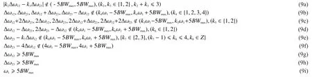

Table II Summary of the Scenarios

Fig.2 Measured Power spectra of the signal with different frequency spacing. (a) Lower band, (b) Upper band

Fig.3 AM/AM and AM/PM characteristics of the PA with/without 2D DPD, under the Scenario DB-I.(a) Lower band,(b) Upper band
It is apparent from Fig. 2 and table III that:for the scenario DB-I, the 2-D-DPD significantly compensates for the in-band intermodulation and cross-modulation distortion and eliminates the out-of-band spectrum regrowth,but for scenario DB-II, the measured ACPR results show that the signal is not linearized properly by the 2-D DPD model. The measured NMSE and PSD results of scenario DBII with DPD is also worse than scenario DBI. The ACPRs are decreased about 12-14 dB compared with scenario DB-I. It is because that the frequency spacing of scenario DB-II does not satisfy the non-overlapping conditions. For scenario DB-II, the 5-th order inband intermodulation and inter-band modulation by-products of the other fundamental bands fall in the interested fundamental bands.These intermodulation products which are not considered by the 2-D DPD model, result in the 2D-DPD method fails to work properly.
4.2 Measurement results for triband model

Fig.4 Measured power spectra of the signal with different frequency spacing. (a)Lower band, (b) Middle band, (c) Upper band
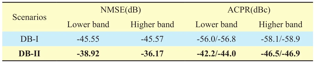
Table III Comparison of ACPRs and NMSEs for dual-band signals with different frequency spacing
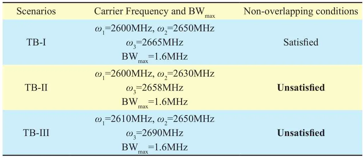
Table IV Summary of measured signals

Table V Comparison of NMSEs for tri-band signals with different frequency spacing

Table VI Comparison of ACPRs and NMSEs for tri-band signals with different frequency spacing
Three tri-band scenarios with different frequency spacing are linearized by the same 3-D DPD models[2] on the same RF PA. The three different scenarios were considered as summarized in Table IV. Among them, scenario TB-I is the only one which satisfy the non-overlapping conditions (9a)-(9i), while the scenarios TB-II and TB-III does not satisfy the conditions. Fig. 4 shows the power spectra of signals at the output of the RF PA for the three scenarios. To be clearly, measurement results of the three scenarios’ were plotted in onefigure, and the center frequency ‘0’ of the bands represent the carrier frequencies of lower/middle/upper bands in different scenarios,respectively. The power spectra marked with rectangles (□), circles (o) and diamonds (◊)illustrates the scenarios TB-I, TB-II and TBIII, respectively. The NMSEs and ACPRs at a 1.6MHz frequency offset for three bands’signals were measured and presented in Table V and VI.
From Fig.4, Table V and VI, we can see that: (1) the out of band distortion of scenarios TB-II and TB-III are stronger than scenarios TB-I. Owing to the existence of IMC products located near the fundamental band, the power spectra of scenario TB-II without DPD shows a strong asymmetry in all three bands. (2) 3-D DPD model work properly for scenario TBI, which can be seen from both NMSE and ACPR results. (3) The linearization performance of scenario TB-II and TB-III are worse than scenario TB-I, the ACPRs are decreased about 10~20 dB compared with the scenario TB-I. (4) The measured NMSEs and ACPRs shown that the 3-D DPD model failed to work properly for scenarios TB-II and TB-III in all three bands. With the same DPD model and RF PAs under-test, the performance of three scenarios vary greatly. It is because that there isn’t HC and IMC products fall in the interested fundamental bands for Scenario TB-I, and a part of 3-rd and 5-th-order IMC products located in the interested fundamental bands for Scenario TB-II, and all of the third-order IMC products (2ω2-ω3), (ω1+ω3-ω2), (2ω2-ω1) and fifth-order IMC products (2ω1-2ω2+ω3), (-ω1+3ω2-ω3), (ω1-2ω2+2ω3) overlap with the interested fundamental bands (band1,band2 and band3) for Scenario TB-III. These HC and IMC products located inside the interested fundamental bands are not taken into consideration by the 3-D DPD model.
From the measurement results, we can draw a conclusion that the performance of multi-dimensional behavioral models are affected by the frequency spacing and bandwidth of multiband signals. The non-overlapping conditions is a sufficient condition to enable a multi-dimensional behavioral models for multi-band or non-continuous carrier aggregation systems.For the scenarios unsatisfied the non-overlapped conditions, the multi-dimensional behavioral models/DPDs should be modified,by taking the unavoidable harmonic and intermodulation products of carriers’ into account.For example, in reference [23], Meenakshi Rawat et.al proposed a H2D MP model for the dual-band concurrent transmission in the presence of harmonic interferences (ω2=2ω1), the proposed model provides NMSE and ACPR improvement as compared to the 2D-DPD model. At the same time, the number of coef ficients of the H2D MP model is also increased significantly (from 180 to 920).
V. CONCLUSION
In this paper, the non-overlapping conditions of multi-band signals to enable the multi-dimensional behavioral models/DPDs for dual-band and tri-band PAs/transmitters are put forward and denoted in the form of closedform expression. To verify the proposed conditions, a set of dual-band/tri-band signals with different frequency spacing and bandwidth are linearized by the same 2D-DPD/3-D DPD models. Measurement results show that the signals which satisfy the non-overlapping conditions can be linearized well, and on the contrary, the other signals which does not satisfy the non-overlapping conditions were not linearized properly, owing to the harmonic and intermodulation products of carriers’ overlap in the interested fundamental bands.
ACKNOWLEDGEMENTS
This work was supported by National Key Basic Research Program of China (973 Program)(No.2014CB339900), the National High Technology Research and Development Program of China (863 Program) (No. 2015AA016801),and National Natural Science Foundations of China (No.61327806).
[1] Younes M, Kwan A, Rawat M, et al.” Linearization of concurrent tri-band transmitters using 3-D phase-aligned pruned Volterra model”.IEEE Transactions on Microwave Theory and Techniques, vol.61, no.12,pp.4569-4578, 2013.
[2] Younes M, Kwan A, Rawat M, et al. “Three-dimensional digital predistorter for concurrent tri-band power amplifier linearization”,Microwave Symposium Digest (IMS), 2013 IEEE MTT-S International. IEEE,pp. 1-4, 2013.
[3] Zheng X, Liu Y, Li S, et al. “A dual-band impedance transformer using pi-section structure for frequency-dependent complex loads”,Progress In Electromagnetics Research C, vol.32,pp. 11-26, 2012.
[4] Li X, Chen W, Zhang Z, et al. “A concurrent dual-band Doherty power amplifier”,IEEE 2010 Asia-Pacific Microwave Conference., pp. 654-657, 2010
[5] Wu Y, Nan L, Jiao L, et al. “Dual-band coupled-line bandpass filter with independently tunable bandwidths”.China Communications,vol.13, no.9, pp. 60-64, 2016.
[6] Saad P, Colantonio P, Piazzon L, et al. “Design of a concurrent dual-band 1.8–2.4-GHz GaNHEMT Doherty power amplifier”,IEEE Transactions on microwave theory and techniques,vol.60, no.6, pp.1840-1849, 2012.
[7] Yang Q, Liu Y, Yu C, et al. “Design and implementation of a high-efficiency concurrent dual-band power amplifier”,The Journal of China Universities of Posts and Telecommunications,vol.21, no.6, pp. 94-99, 2014.
[8] Costanzo F, Giofrè R, Piazzon L, et al. “A design method for concurrent tri-band Doherty Power Amplifier”,Wireless Symposium (IWS), 2015 IEEE International, pp.1-3, 2015.
[9] Khan M S, Zhang H, Pengfei H E, et al. “A PHEMT Based Wideband LNA for Wireless Applications“.China Communications, vol.12,no.10, pp. 108-116, 2015.
[10] Dai Z, He S, You F, et al. “A new distributed parameter broadband matching method for power amplifier via real frequency technique”,IEEE Transactions on Microwave Theory and Techniques, vol.63,no.2,pp. 449-458, 2015.
[11] Chen K, Peroulis D. “Design of broadband highly efficient harmonic-tuned power amplifier using in-band continuous class-mode transferring”,IEEE transactions on microwave theory and techniques, vol.60,no.12,pp. 4107-4116, 2012.
[12] Bassam S A, Helaoui M, Ghannouchi F M. “2-D digital predistortion (2-D-DPD) architecture for concurrent dual-band transmitters”,IEEE Transactions on Microwave Theory and Techniques,vol.59,no.10,pp. 2547-2553, 2011.
[13] Liu Y J, Chen W, Zhou J, et al. “Digital predistortion for concurrent dual-band transmitters using 2-D modified memory polynomials”,IEEE Transactions on Microwave Theory and Techniques, vol.61,no.1,pp. 281-290, 2013.
[14] Chen W, Zhang S, Liu Y J, et al. “Efficient Pruning Technique of Memory Polynomial Models Suitable for PA Behavioral Modeling and Digital Predistortion”,IEEE Transactions on Microwave Theory and Techniques, vol.62,no.10,pp. 2290-2299, 2014.
[15] Fehri B, Boumaiza S. “Baseband equivalent Volterra series for digital predistortion of dual-band power amplifiers”,IEEE Transactions on Micro-wave Theory and Techniques,vol. 62,no.3,pp.700-714, 2014.
[16] Zhang T, Yu C, Liu Y, et al. A Low-Complexity Dual-Band Model for Dual-band Power Ampliif ers Based on Volterra Series”,Progress In Electromagnetics Research Letters, vol.53, pp. 101-106, 2015.
[17] Xiang H, Yu C, Gao J, et al. “Dynamic deviation reduction‐based concurrent dual‐band digital predistortion”,International Journal of RF and Microwave Computer-Aided Engineering,vol.24,no.3,pp. 401-411, 2014.
[18] Xiang H, Yu C, Gao J, et al. “Concurrent dual‐band digital predistortion method for wideband power amplifier with large carrier spacing two‐carrier signal”,Microwave and Optical Technology Letters, vol.56,no.3,pp. 594-597, 2014.
[19] Liu Y J, Chen W, Zhou J, et al. “Joint predistortion of IQ impairments and PA nonlinearity in concurrent dual-band transmitters”,Microwave Conference (EuMC), 2012 42nd European.IEEE,pp.132-135, 2012.
[20] Younes M, Ghannouchi F M. “On the modeling and linearization of a concurrent dual-band transmitter exhibiting nonlinear distortion and hardware impairments”,IEEE Transactions on Circuits and Systems I: Regular Papers, vol.60,-no.11, pp. 3055-3068, 2013.
[21] Younes M, Ghannouchi F M. “Behavioral modeling of concurrent dual-band transmitters based on radially-pruned Volterra model”,IEEE Communications Letters, vol.19,no.5,pp. 751-754,2015.
[22] Mkadem F, Islam A, Boumaiza S. “Multi-Band Complexity-Reduced Generalized-Memory-Polynomial Power-Amplifier Digital Predistortion”,IEEE Transactions on Microwave Theory and Techniques, vol.64,no.6,pp. 1763-1774,2016.
[23] Rawat M, Roblin P, Quindroit C, et al. “Concurrent Dual-Band Modeling and Digital Predistortion in the Presence of Unfilterable Harmonic Signal Interference”,IEEE Transactions on Microwave Theory and Techniques, vol.63,no.2,pp.625-637, 2015.

- China Communications的其它文章
- Open Access Strategy in Cloud Computing-Based Heterogenous Networks Constrained by Wireless Fronthaul
- Orchestrating Network Functions in Software-Defined Networks
- RGB Based Multiple Share Creation in Visual Cryptography with Aid of Elliptic Curve Cryptography
- Distributed Document Clustering Analysis Based on a Hybrid Method
- Action Recognition with Temporal Scale-Invariant Deep Learning Framework
- High-Performance Beamformer and Low-Complexity Detector for DF-Based Full-Duplex MIMO Relaying Networks