
Compact Coplanar Epsilon-Negative Antenna with Ultra-Wide Band Character
2017-05-08 01:46JunTaoQuanyuanFengZongliangZheng
China Communications 2017年2期
Jun Tao, Quanyuan Feng, Zongliang Zheng
Institute of Microelectronics, Southwest Jiaotong University, Chengdu 611756, China
* The corresponding author, email: fengquanyuan@163.com
I. INTRODUCTION
In the decade years, the antennas with compact sizes were studied and proposed to satisfy the requirements of the rapidly developing modern communication devices, especially for the small and compact handle devices.Moreover, the modern communication modes become more and more complex, and thus wide or ultra-wide communication spectrums are also needed. Among these studies, the electromagnetic metamaterial (MTM) antennas have aroused extensive attention due to their specific physical features. Multiple MTM antennas based on composite right/left-handed(CRLH), epsilon-negative (ENG) and mu-negative (MNG) unit cells were proposed [1-3].These MTM antennas can control their phase velocities of the input waves to resonate at desired frequencies by modifying the parameters of equivalent circuits. The most common utilization of the MTM antenna is the zeroth-order resonant (ZOR) mode whose propagation constant is equal to zero. Thus, the physical length is vanished and the resonant frequency is only determined by the parameters of the equivalent circuit, which means that the resonant frequency is irrelevant with its physical size and the antenna can possess extremely compact size. However, the quality factor of the ZOR mode is pretty high, which causesnarrow bandwidth, low gain and low radiation efficiency. Furthermore, many MTM antennas can possess multiple resonant modes through fine-tune feeding structures. Unfortunately,these isolated resonant modes can hardly merge into one wide bandwidth due to high quality factor and flat dispersion curve [4-7].These problems are the emphases of the studies for MTM antennas.
In order to solve the mentioned problems,bandwidth merging and expansion technologies were studied for the MTM antennas with high gain and radiation efficiency [8-16]. In ref. [8], the mushroom-array MTM antenna was proposed and the fundamental TM10and TM20modes of the antenna were merged into one wide bandwidth due to the dispersion features of the unit cells. The antenna adopted the slot-coupling feeding structure, which leaded to good impedance matching and high gain. However, the size and number of the unit cell were considerable to achieve the specific phase shift in the MTM array. In ref. [9], the modified ground plane, which worked as an extra resonator, was introduced to the proposed CRLH antenna. The bandwidth generated by the ground plane merges with the ZOR and FROR bandwidths of CRLH cells, which can entirely cover the UWB spectrum. In ref.[10-12], the theoretical methods to obtain the wide ZOR bandwidth were provided. These antennas can extend their ZOR bandwidth through changing the values of distribution parameters of the equivalent circuits. Notice that,the parameters, which influenced the ZOR bandwidth, were not same for open-ended and short-ended MTM antennas and the theoretical analyses didn’t consider the impedance matching at the input terminals. These theoretical analyses, however, did provide a clear guideline for ZOR bandwidth expansion. The EBG-like ground planes were employed in ref. [13-14] and this was the new method to achieve the wide ZOR frequency. However, the limited improvement, complex ground design and the in fluence in impedance matching were the defects of such structures. Meanwhile, it was difficult to obtain the multiple modes merging.
In this paper, a compact coplanar ENG antenna, with small size of 18×11.5 mm2, is proposed and the ultra-wide bandwidth is also achieved. Owning to the coplanar structure,the via-free feature is obtained, which benefits the convenient tuning of the ZOR frequency and extension of the ZOR bandwidth. In the other hand, the via-free feature also brings more degrees freedom for the antenna design.The shunt left-handed inductance of the ENG unit cell is integrated between the radiating patch and the ground, and it has slight influence to the high-order resonances of the proposed antenna. Therefore, by merging the ZOR and high-order resonant bandwidths into one single band, the ultra-wide bandwidth from 5.25 to 13 GHz, is achieved. The proposed ENG antenna also obtains high and relatively stable peak gains and radiation efficiency. The approximately omin-directional feature is achieved in its H-plane. These advantages of the proposed antenna indicate that it is a competitive candidate for modern handle wireless devices.
II. DESIGN AND ANALYSES OF THE ENG ANTENNA
Fig. 1(a) shows the configuration and prototype of the proposed coplanar epsilon-negative antenna. It is printed on the F4b-2 substrate with compact size of 18×11.5 mm2, relative dielectric constant of 2.65 and thickness of 0.8 mm. The equivalent circuit model of the ENG unit cell is shown in Fig. 1(b) including the series inductance (LR), shunt inductance (LL) and shunt capacitance (CR).
2.1 ZOR mechanism and bandwidth extension
In fig. 1(b), the equivalent circuit model is derived from the CRLH transmission line model.As for epsilon-negative transmission line, the series capacitance is removed from the CRLH transmission line. The meandering metallic line provides the shunt inductance for the proposed antenna. The shunt capacitance and series inductance are the inherent properties of the normal transmission line. The dispersion equation of the ENG-TL can be obtained similarly by applying the Bloch and Floquet theory to the unit cell of period structure [15]:

Fig.1 (a) Geometry and fabricated prototype of proposed ENG antenna, (b) Equivalent circuit model. W = 11.5, L = 18, l1 = 4.5, l2 = 3.2, l3 = 5.5, l4 = 0.2, l5 =1.6, ws = 0.7, wf = 1.6, wp = 6.5, wm = 0.3, w1 = 2.6, w2 = 5.9, w3 = 3, t = 0.1(unit: mm)
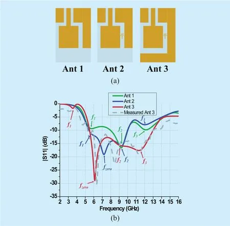
Fig.2 (a) Evolution processes of ENG antenna, (b) Simulated and Measured |S11|.


where n is the resonance mode, N is the number of the unit cell, and l is the total length of the ENG-TL, respectively. Thus, when n=0,the ZOR mode happens and the propagation constant equals to zero, which means that the propagating wavelength is infinite and it is independent on the physical length of the antenna. The ZOR frequency can be calculated according to (1) and (2), and it is shown as below:

It can be observed that the ZOR frequency is able to be modified by altering LLand CR. Furthermore, considering the open ended ENG-TL, it only dependents on the series admittance. The average electric energy stored in the shunt capacitance CRand the average magnetic energy stored in the shunt inductance LL. The relationship between the Q factor and bandwidth can be computed in (4):

It indicates that the bandwidth is inverse proportion to the CR. Thus, the coplanar structure is prone to possessing smaller shunt capacitance and extending the bandwidth. As aforementioned, this coplanar structure also brings the via-free feature, decreasing the complexity of antenna design and fabrications.
2.2 Studies of the ENG antenna
The proposed ENG antenna is shown in Fig.1(a). It is designed based on a simple monopole antenna, and a protruded ground is added in the right to help construct the ground of the ENG unit cell. A meandering metallic line connects the radiating patch and the protruded ground. Notice that, the protruded ground also generates a low resonant frequency. However, its performance is undesirable due to the impedance mismatching, and the protruded ground has significant effects on the high-frequency impedance matching. Thus, here, we primarily regard the protruded ground plane as a matching network and optimize it to be a half slot structure to achieve ultra-wide bandwidth. The proposed antenna is fed by the CWP-fed structure which is tuned to be 50 Ohm.
To further study the operation mechanism,the evolution processes of the proposed antenna are shown in Fig. 2(a). Ant 1 is the basic monopole antenna with a protruded ground plane, Ant 2 is Ant 1 with a meandering metallic line, forming the original ENG antenna,and Ant 3 is the proposed antenna. The simulated re flection coefficients of these antennas are illustrated in Fig. 2(b). It can be found that Ant 1 generates three resonant frequencies(f1=5.7, f2=9.3 and f3=12.2 GHz). As for Ant 1,the length of the current path in the protruded ground approximates to 11.4 mm that is about quarter wavelength corresponding to 5.7 GHz,and the higher resonant frequencies, f2and f3,are the high-order resonant modes of Ant 1. In order to specify the operating mechanism of Ant 1, the current distributions are depicted in Fig. 3(a) at 5.7, 9.3 and 12.2 GHz, respectively. At 5.7 GHz, the currents mainly distribute on the protruded ground and a quarter-wavelength current path can be found. Lots of currents concentrate on the left slot at 9.3 GHz,while those currents concentrate on right slot at 12.2 GHz, which illustrates that the higher frequencies have significant relevance with these slots. When the meandering metallic line is introduced to Ant 1, a new resonant frequency, denoted as fzero, at 7.2 GHz appears, while the other frequencies nearly remain unchanging. Thus, a wider bandwidth is achieved by merging f1, f2and fzero. The dispersion curve is shown in Fig. 4(a), and the electric filed distribution of Ant 2 at 7.2 GHz is depicted in Fig. 4(b). It can be observed that the simulated ZOR frequency occurs around 7 GHz, which almost accords with the fzeroof Ant 2. The slight frequency shift between the ZOR frequencies of the re flection coefficient of Ant 2 and the dispersion of the unit cell results from the impact of impedance matching. Moreover,the electric filed has the same attitude and phase in the ENG unit cell at 7.2 GHz, which is the typical ZOR electric filed distribution.The currents distributions of Ant 2, at 7.2, 9.3 and 12.2 GHz, are also shown in Fig. 3(b). At higher frequencies, f2and f3, Ant 2 and Ant 1 have the similar current distributions, which indicates that the meandering metallic line has slight in fluence on the higher resonant modes.To extend the bandwidth of Ant 2, a long in-verse L-shaped protruded ground plane is introduced. As seen from Fig. 2(b), the proposed antenna possesses a wider bandwidth, from 5.5 to 13 GHz, and its ZOR frequency moves to lower frequency, 6.14 GHz, due to the increasing of CR. f3is also decreased, while its higher frequency, f2, remains relatively stable.Increasing the protruded ground plane will introduce a larger shunt capacitance and it may narrow the ZOR bandwidth according to (4).But the impedance matching of whole bandwidth is improved. Thus, the inverse L-shaped ground brings more benefits rather than disadvantages. The current distributions of Ant 3, at 6.1, 9.3 and 11.6 GHz, are shown in Fig.3(c), and it can be observed that the currents distributions of 9.36 and 11.6 GHz are similar as those of Ant 2. The third resonant frequency, f3, of Ant 3 declines mainly due to the extension of the current path on the protruded ground plane.

Fig.3 Current distributions of (a) Ant 1, (b) Ant 2 and (c) Ant 3

Fig.4 (a) Dispersion curve of the unit cell, (b) Simulated electric field at 7.2 GHz
2.3 The high resonant modes
To verify the relationships between the high frequencies and the slots, the high resonant modes are studied in this part based on Ant 2. When we investigate f2, Ant 2 with and without the left ground are simulated using HFSS and the simulated results are depicted in Fig. 5(a). It can be observed that the resonant frequency at 9.3 GHz vanishes when the left ground plane is removed, while the other resonant frequencies remain unchanging.Thus, the left slot primarily generates f2and it also influences the impedance matching of the proposed antenna. When we investigate the f3, we can’t directly delete the right ground like above simulations. Directly removing the right ground will cause severe impedance mismatching, which is adverse to our investigations. Therefore, we change the length of the inverse L-shaped protruded ground. Three different lengths are chosen to be the references and the simulated results are shown in Fig.5(b). Notice that, the initial vertical length, Len,of the protruded ground of Ant 2 is 8.5 mm.With the increasing of length of the protruded ground, fzeroand f2approximately remain unchanged, while f1and f3observably move to the lower frequency.
The slight frequency shift happens for fzeromainly due to the increasing of CR.
Thus, the left slot primarily determines the f2, while the right slot determines the f1and f3.Modifying the ground plane causes the changes of the impedance matching and then the ground plane can be regarded as the matching network for the proposed antenna. The sizes of the inverse L-shaped protruded ground are optimized through the multiple experiments and optimizations.
III. RESULTS AND ANALYSES OF THE ENG ANTENNA
3.1 The impedance bandwidth

Fig.5 (a) Simulated |S11| of Ant 2 with or without left ground, (b) Simulated |S11| of different Len

Fig.6 (a) E-plane, (b) H-plane
The impedance performance of the proposed antenna is measured by the Agilent E5071C vector network analyzer. As depicted in Fig.2(b), the measured impedance bandwidth(|S11| < -10 dB) is from 5.25 to 13 GHz. The discrepancies between the simulated and measured reflecting coefficients are acceptable.The measured results indicate that proposed ENG antenna achieves an ultra-wide bandwidth and it can completely covers the upper band of the UWB communication.
3.2 Radiation performance
The 2-D radiation patterns (xoz- and yozplanes) at 6, 9 and 12 GHz of the proposed ENG antenna are plotted in Fig. 6. As observed, the xoz-plane is the E-plane while the yoz-plane is the H-plane for the proposed antenna. The proposed antenna achieves quasi-omnidirectional radiation in H-plane at low frequencies. At higher frequencies, the H-plane slightly orientates towards –y axis due to the re flection effects of the protruded plane,and the radiation patterns of E- and H-planes are not regular resulting from the complex currents distributions.

Fig.7 Peak gains and radiation efficiency
The peak gains and radiation efficiency of the proposed antenna are shown in Fig. 7.A relatively average peak gains are obtained around 3.5 dBi over the frequency band of 5-14 GHz. At the ZOR frequency, the high peak gain reaches 3 dBi. The radiation efficiency is above 90% in most of the operation frequency band.
IV. CONCLUSION
In this paper, an ENG antenna with very compact size of 18×11.5 mm2has been fabricated and measured. The ENG unit cell has slight influence on the high resonant modes of the half slot structure and they generate three main resonant frequencies, which provides a wide impedance bandwidth from 5.25 to 13 GHz,covering the upper band of UWB communication. Quai-omnidirectional radiation patterns and relatively stable gains guarantee the antenna with superior radiation performance. These superiorities of the proposed ENG antenna indicates that it is competitive for portable devices.
ACKNOWLEDGEMENT
This work was supported by the National Natural Science Foundation of China (NNSF)under Grant 61531016, National Natural Science Foundation of China (NNSF) under Grant 61271090, Sichuan province science and technology support project under Grant 2016GZ0059 and Sichuan province science and technology support project under Grant 2017GZ0110.
[1] Zhou C., Wang G., Wang Y., Zong B., Ma J.,“CPW-fed Dual-band Linearly and Circularly Polarized Antenna Employing Novel Composite Right/Left-handed Transmission-line”,IEEE An-tennas & Wireless Propagation Letters,vol.12,PP.1073 - 1076, Aug., 2013.
[2] Chen, P. W., and Chen, F. C., “Asymmetric Coplanar Waveguide (ACPW) Zeroth-Order Resonant(ZOR) Antenna with High Efficiency and Bandwidth Enhancement”,IEEE Antennas & Wireless Propagation Letters, vol.11.9, PP.527 - 530, May,2012.
[3] Rezaeieh, S. A., Antoniades, M. A., and Abbosh,A. M., “Bandwidth and Directivity Enhancement of Loop Antenna by Nonperiodic Distribution of Mu-Negative Metamaterial Unit Cells”,IEEE Transactions on Antennas & Propagation,vol.64,PP. 3319 - 3329, June, 2016.
[4] Lai, A., Leong, K. M. K. H., and Itoh, T., “In finite Wavelength Resonant Antennas with monopolar radiation pattern based on periodic structures”,IEEE Transactions on Antennas & Propagation,vol.55, PP.868 - 876, March, 2007.
[5] Amani N. and Jafargholi, A., “Zeroth-Order and TM10Modes in One-Unit Cell CRLH Mushroom Resonator”,IEEE Antennas & Wireless Propagation Letters,vol.14, PP.1396 - 1399, March, 2015.
[6] Dong, Y., and Itoh, T., “Miniaturized Substrate Integrated Waveguide Slot Antennas Based on Negative Order Resonance”,IEEE Transactions on Antennas & Propagation,vol.58, PP.3856 -3864, Sep., 2010.
[7] Lee, H. M., “A Compact Zeroth-Order Resonant Antenna Employing Novel Composite Right/Left-Handed Transmission-Line Unit-Cells Structure”,IEEE Antennas & Wireless Propagation Letters,vo.10, PP.1377 - 1380, Nov., 2011.
[8] Liu, W., Chen, Z. N. and Qing, X., “Metamaterial-based Low-Profile Broadband Mushroom Antenna”,IEEE Transactions on Antennas &Propagation,vol.62, PP.1165 - 1172. Dec., 2013.
[9] Lee, H., Woo, D., and Nam, S., “Compact and Bandwidth-Enhanced Asymmetric Coplanar Waveguide (ACPW) Antenna Using CRLH-TL and Modified Ground Plane”,IEEE Antennas &Wireless Propagation Letters,vol.15, PP.810 -813, Sep., 2015.
[10] Yang, S. Y. and Ng, M. K. M., “A Bisected Miniaturized ZOR Antenna with Increased Bandwidth and Radiation Efficiency”,IEEE Antennas& Wireless Propagation Letters,vol.12, PP.159 -162, Jan., 2013.
[11] Jang, T., Choi, J., and Lim, S., “Compact Coplanar Waveguide (CPW)-Fed Zeroth-Order Resonant Antennas with Extended Bandwidth and High Efficiency on Vialess Single Layer”,IEEE Transactions on Antennas & Propagation,vol.59, PP. 363- 372, Dec., 2010.
[12] Chi, P. L. and Shih, Y. S., “Compact and Bandwidth-Enhanced Zeroth-Order Resonant Antenna”,IEEE Antennas & Wireless Propagation Letters,vol.14, PP.285 - 288, Oct., 2015.
[13] Sharma, S. K., Gupta, A., and Chaudhary, R. K.,“Epsilon Negative CPW-Fed Zeroth-Order Res-onating Antenna with Backed Ground Plane for Extended Bandwidth and Miniaturization.IEEE Transactions on Antennas & Propagation,vol.63,PP.5197 - 5203, Sep., 2015.
[14] Liu, L. Y., and Wang, B. Z., “A Broadband and Electrically Small Planar Monopole Employing Metamaterial Transmission Line”,IEEE Antennas& Wireless Propagation Letters,vol.14, PP.1018 -1021, Jan., 2015.
[15] Park, J. H., Ryu, Y. H., Lee, J. G., and Lee, J. H.,“Epsilon Negative Zeroth-Order Resonator Antenna”,IEEE Transactions on Antennas & Propagation, vol.55, PP.3710 - 3712, Dec., 2007.

- China Communications的其它文章
- Open Access Strategy in Cloud Computing-Based Heterogenous Networks Constrained by Wireless Fronthaul
- Orchestrating Network Functions in Software-Defined Networks
- RGB Based Multiple Share Creation in Visual Cryptography with Aid of Elliptic Curve Cryptography
- Distributed Document Clustering Analysis Based on a Hybrid Method
- Action Recognition with Temporal Scale-Invariant Deep Learning Framework
- High-Performance Beamformer and Low-Complexity Detector for DF-Based Full-Duplex MIMO Relaying Networks