
Design of double-layer active frequency-selective surface with PIN diodes for stealth radome∗
2017-08-30 08:25BinDeng邓斌andJianChen陈健
Chinese Physics B 2017年9期
关键词:陈健
Bin Deng(邓斌)and Jian Chen(陈健)
1 Department of Electronic Science and Engineering,Nanjing University,Nanjing 210093,China
2 Nanjing Research Institute of Electronics Technology,Nanjing 210039,China
Design of double-layer active frequency-selective surface with PIN diodes for stealth radome∗
Bin Deng(邓斌)1,2,†and Jian Chen(陈健)1
1 Department of Electronic Science and Engineering,Nanjing University,Nanjing 210093,China
2 Nanjing Research Institute of Electronics Technology,Nanjing 210039,China
An experimental double-layer active frequency-selective surface(AFSS)for stealth radome is proposed.The AFSS is a planar structure which is composed of a fixed frequency-selective surface(FSS),a PIN diodes array,and a DC bias network.The AFSS elements incorporating switchable PIN diodes are discussed.By means of controlling the DC bias network,it is possible to switch the frequency response for reflecting and transmitting.Measured and simulated data validate that when the incidence angle varies from 0°to 30°the AFSS produces more than−11.5 dB isolation across 6–18 GHz when forward biased.The insertion loss(IL)is less than 0.5 dB across 10–11 GHz when reverse biased.
frequency-selective surface(FSS),active frequency-selective surface(AFSS),PIN diode,stealth radome
1.Introduction
The frequency-selective surface(FSS)has been widely employed in stealth radome,[1]it can reduce the radar cross section(RCS)of the antenna greatly out of band.[1,2]A suitable FSS radome can allow the electromagnetic wave to pass in the operating frequency and reject the wave out of band. Varieties of FSSs have been researched,[3–6]but the frequency responses of the FSSs are fixed and mostly lie on the periodic arrays of the FSSs once designed and manufactured.
If the frequency response of the FSS can be varied in response to an applied electrical or optical control signal,then it is possible to realize an active or adaptive FSS(AFSS) structure.[7–16]One approach to achieving AFSS is to incorporate active devices into the FSS structure,resistors,[2]solidstate varactor diodes,[10–12]and MEMS switches[14]are generally used in the AFSS units.However,because of the intrinsic capacitance and inductance effect of the biased network on the AFSS frequency response,these AFSSs usually exhibit a narrow bandwidth frequency response[9]and lack of large beam scanning capability.[7,16]
In this contribution,a novel PIN-tunable,band-pass AFSS radome with an embedded bias network is proposed. Compared with the AFSS reported in the literature,[7–14]the proposed strategy has two main advantages.First,a simple biased strategy is proposed to design a switchable AFSS.Then, the functional band-pass and wide-band RCS reduction are tunable by simply adjusting the bias state of the PIN diodes. Second,wide-band,large-scan angle,and dual-polarized characteristicsare achieved by simply designing the transformative square ring slot unit cell.
The frequency response of the proposed AFSS is demonstrated through full-wave EM numerical simulations using CST software.[15]To verify the simulations,a sample using PIN diodes is fabricated and measured in an anechoic chamber,the transmission coefficients and RCS of the sample are measured at different incidence angles for horizontal and vertical polarizations.An excellent transmission property when reverse biased and a wide-band RCS reduction when forward biased are verified by the present theoretical and experimental results.
2.Design and analysis
Figure 1 shows the configuration of the proposed AFSS. The proposed AFSS radome in this paper is composed of two single-layer AFSSs and a layer of foam(εr=1.1,tanδ= 0.005)spacer placed between them.The single-layer AFSS radome is composed of two metallic layers separated by a dielectric substrate,the material of the dielectric substrate is selected as FR4 with a permittivity 2.33 and a loss tangent of 0.001.The top layer consists of an etched transformative square ring slot pattern and the surface-mounted PIN diodes welded in the top layer manually positioned as shown in Fig.1(b).The bottom layer is a DC bias network.The PIN diodes array and DC bias network are connected by metal vias.
The transformative square ring slot elements are arranged on a dielectric substrate in a rectangular lattice,which are selected to provide the wide-band,large-scan angle,and dualpolarized response.The layer of the foam spacer serving asa connection between the two single-layer AFSSs can enlarge the operating bandwidth of the proposed radome.Active control of the AFSS impedance is achieved by loading four high barrier silicon PIN diodes placed orthogonally.The DC bias network incorporating into the AFSS structure is designed as the excitation line to supply a bias voltage to the PIN diodes.
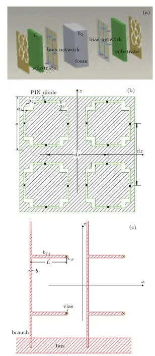
Fig.1.(color online)Structure of the proposed AFSS:(a)cross section, (b)top layer,(c)DC bias network.
To make the frequency response controllable,the most effective way is to alter the working state of the AFSS.By means of DC bias voltage applied to the PIN diode,the transmission and scatter properties of the switchable AFSS radome can be effectively characterized.
Generally speaking,a PIN diode could be converted into a series and parallel RLC equivalentcircuit,such as the scheme described in Ref.[17],Roff,Ron,Con,and Coffare the intrinsic resistances and capacitances of the PIN diode in the on-and off-state,respectively.When the PIN diodes are reverse biased or zero biased,the equivalent resistance Roffis extremely large,the PIN diodes are equivalent to a large resistance shunt capacitor.Under the influence of equivalent capacitance Coff, the resonant frequency of the AFSS can be shifted to lower frequency.In contrast,when forward biased,the equivalent resistance Ronof the PIN diode is smaller,hence the short circuit path is formed between the units and the units are connected together like a metal surface.When the AFSS properly leans, the incidence energy is redirected into off-normal directions by the AFSS,which enables the effective monostatic RCS to reduce in near-normal directions.
3.Computational method
To validate the properties of the proposed AFSS,fullwave EM simulation software CST is employed to simulate and optimize the AFSS with 1)miniaturized structure,2)extended functional band,and 3)maximized transmission coefficients.
In this study,the transmitting frequency of the band-pass AFSS is designed to be 10.5 GHz,and the conductivity of the copper is set as 5.8×10⁷S/m.The equivalent capacitance Coffof the PIN diode is assumed to be 0.1 pF,resistance Roffis assumed to be 30 kΩ,and resistance Ronis assumed to be 10 Ω. The detailed geometrical dimensions of the structure are given in Table 1.
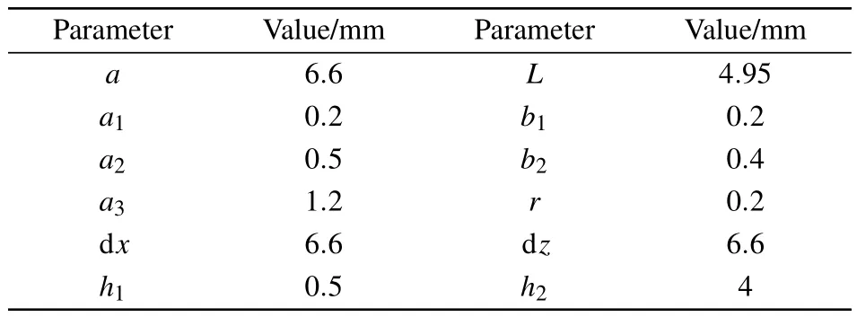
Table 1.Parameters of the AFSS.
Firstly,to study the effect of the PIN diodes on the FSS frequency response,the proposed AFSS,together with a primary FSS without PIN diodes is simulated using CST software.The simulated results of their transmission coefficients at normal incidence are shown in Fig.2.The center resonant frequency could shift from 14 GHz to 10.5 GHz,and the operating bandwidth is also decreased,due to the influence of capacitance Coffof the PIN diodes.Besides,to study the effect of the bias network on the AFSS frequency response,the proposed AFSS,compared with an AFSS without bias network, is also simulated.It is shown that the bias network could also decrease the operating bandwidth,so the design of the bias network is very important for a practical AFSS radome.Because of the effect of the bias network on the FSS frequency response,biasing the PIN diodes properly is a major difficulty in designing a switchable AFSS.

Fig.2.(color online)The simulated transmission coefficients.

Fig.3.(color online)The simulated transmission coefficients with varied incidence wave angles(reverse biased):(a)horizontal polarization, (b)vertical polarization.
The transmission coefficients at different incidence wave angles for horizontal and vertical polarizations when reverse biased are depicted in Fig.3.As shown in Fig.3(a),the horizontal polarization transmission bandwidth declines with the increasing incident angle,simultaneously,the horizontal polarization transmission coefficient deteriorates with the increasing incident angle especially when exceeding 60°.As shown in Fig.3(b),the vertical polarization transmission bandwidth will augment with the increasing incident angle, whereas,the vertical polarization transmission coefficient is almost invariable in the operating bandwidth,which means that the vertical polarization is much more stable compared with the horizontal polarization for the structure.
When forward biased,the transmission coefficients at different incidence wave angles for horizontal and vertical polarizations are shown in Fig.4.The transmission coefficients of the AFSS are less than 2%across 0–20 GHz for horizontal and vertical polarizations when the PIN diodes are in on-state.It means that more than 98%energy of the incidence wave is refl ected.So,it acts like a metal surface re flecting the incidence wave.This design of AFSS on transmission has a good inhibitory effect in the range of 0–20 GHz when reverse biased.
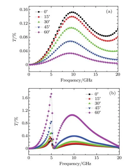
Fig.4.(color online)The simulated transmission coefficients at different incidence wave angles:(a)horizontal polarization,(b)vertical polarization.
4.Experimental validation
Based on the design in Fig.1,an experimental AFSS radome was constructed on an FR4 printed circuit board using standard photo-etching techniques.Figure 5 demonstrates a photograph of the AFSS radome.The board has a dimension of 180 mm×100 mm and contains 728(14×26)unit cells with the copper thickness of 18µm.2912(14×26×4)PIN diodes (MA4E2502,MACOM)were mounted in the AFSS.
The frequency response was measured across 6–18 GHz by putting the sample on a clamp between two wide-band horn antennas connected to the network analyzer(Agilent N5244A) in the anechoic chamber of Nanjing Research Institute of Electronics Technology.The two wide-band horn antennas were placed about 2 m away from the random surface and had the same height as the AFSS.
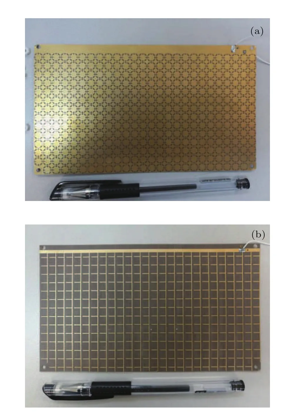
Fig.5.(color online)The AFSS:(a)top view of the sample,(b)bias network.
To verify the stability of the AFSS radome,[13]we measured the transmission coefficients in vertical and horizontal polarizations for different incident angles.As shown in Fig.6, when zero biased or reverse biased,the transmission coefficients keep almost constant from 0°to 30°.A band-pass effect at the resonance frequency of 10.5 GHz is achieved.The operating bandwidth achieves 1 GHz for the transmission coefficients exceeding 90%(−0.5 dB).The simulated results in Fig.3 agree well with the experimental results.As depicted in Fig.6(b),the transmission coefficients of vertical polarization exceed 100%when the incidence wave angle equals 15°, this is impossible obviously;this is mainly due to the small sample,causing the electromagnetic wave diffraction after repeated verification.The slight discrepancy is acceptable considering the edge effect and finite unit cells.
As shown in Fig.7,when forward biased,the AFSS radome presents perfect reflection characteristic,the transmission coefficients are less than 7%(−11.5 dB)across 6–18 GHz in horizontal polarization.The transmission coefficients are less than 2.5%(−16 dB)across 6–18 GHz in vertical polarization.The experimental results are slightly larger than the calculated ones shown in Fig.4.Discrepancies can be observed between the simulated and the measured results.The reasons are given as follows:1)the incidence wave is plane wave in simulation,while the far-field radiation from the horn aperture can hardly be regarded as the standard plane wave;2) the not-perfectness of the absorbing material in the anechoic chamber;and 3)fabrication tolerance and misalignments in the measurement setup.Nevertheless,the AFSS still exhibits total reflection characteristic across 6–18 GHz when forward biased.
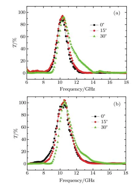
Fig.6.(color online)The measured transmission coefficients with varied incidence wave angles(reverse biased):(a)horizontal polarization, (b)vertical polarization.
However,due to the small size of the AFSS sample and the wider main lobe beam-width of the testing horn antenna, the experiment result only covers the angle from 0°to 30°; when the incidentangle exceeds 30°,the frequency resonances deteriorate seriously.
Moreover,to investigate the wide-band scattering performance and stealth characteristic of the AFSS,the monostatic RCS results of the AFSS sample(180 mm×100 mm)for different frequencies and different incidence wave angles were also measured when forward biased.A metal surface is a perfect electric conductor(PEC),it is often used as a reference in RCS calculations or experiment.[4,18]In this paper,a metal surface with the same size(180 mm×100 mm)works as the reference in the anechoic chamber as shown in Fig.9.
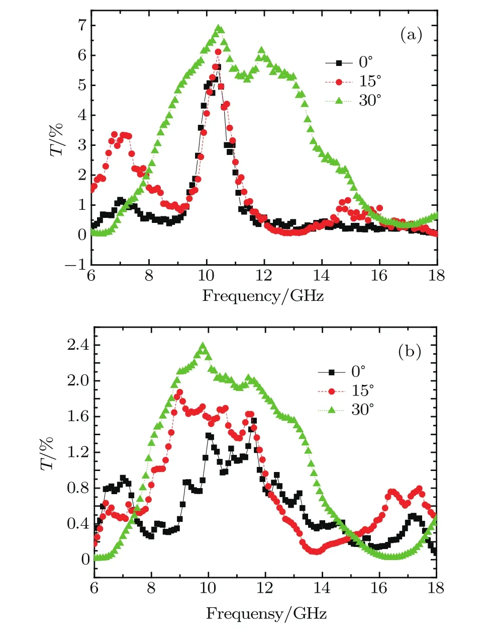
Fig.7.(color online)The measured transmission coefficients with varied incidence wave angles:(a)horizontal polarization,(b)vertical polarization.
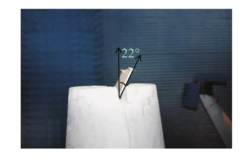
Fig.8.(color online)RCS test scenario.
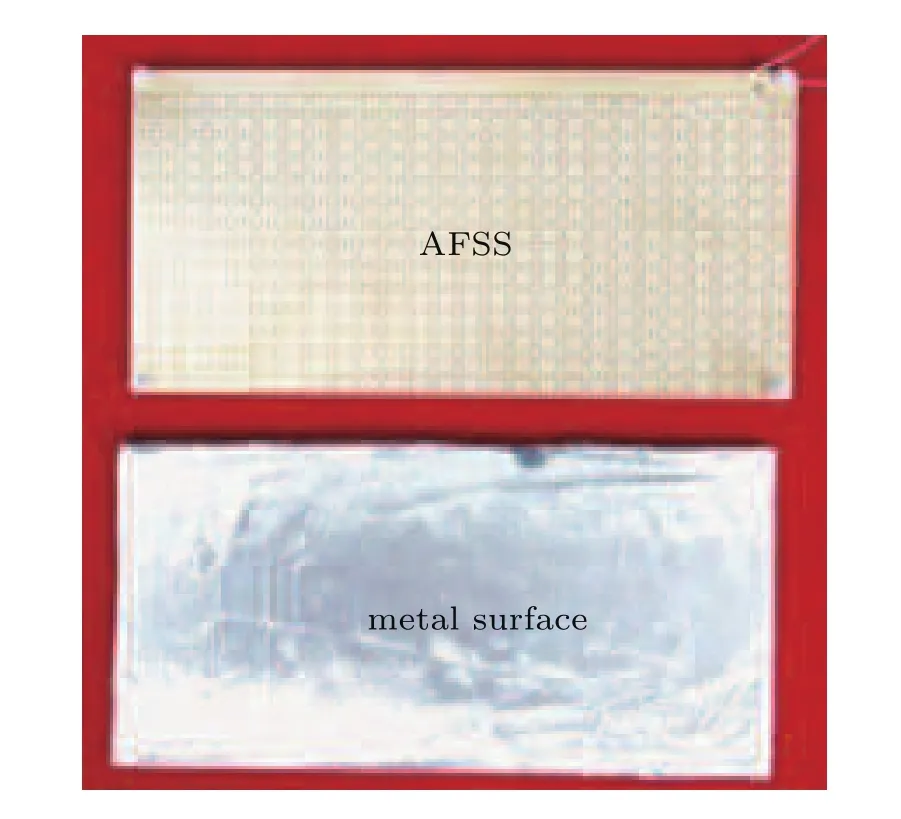
Fig.9.(color online)Sample to be measured.
As shown in Fig.8,the sample to be measured is fixed in a foam shelf which tilts 22°in a vertical direction.Two X-band horn antennas are placed at 10 m away from the AFSS and have the same height as the AFSS,in addition,the two horn antennas must be put together,so the two horn antennas can be regarded as being located at the same spot.When the incidence wave impinges,it could be redirected in noncritical directions,then the monostatic RCS can be reduced greatly.
To verify this hypothesis,the normalized monostatic RCS of the AFSS with respect to the metal surface at the center frequency(f=10 GHz)in vertical and horizontal polarizations for different incident angles is shown in Fig.10.At the center frequency,the proposed AFSS sample exhibits almost the same RCS reduction characteristics as the metal surface from−45°to+45°.In addition,we also measured the average monostatic RCS of the AFSS sample versus the incidence wave angle and frequency compared to the metal surface as shown in Table 2.The measured RCS reduction bandwidth is from 8 GHz to 12 GHz and the incidence wave angle of the plane wave is set to be−45°to 45°.The experimental results indicate that the AFSS has−19.6 dB average RCS reduction for vertical polarization and−23.9 dB average RCS reduction for horizontal polarization.
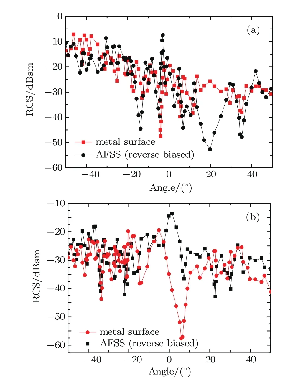
Fig.10.(color online)RCS versus incidence angle(f=10 GHz).
The above experimental results demonstrate that the monostatic RCS across−45°to 45°direction is reduced greatly by the AFSS from 8 GHz to 12 GHz.It exhibits almost the same RCS reduction characteristics,so the proposed AFSS when forward biased has the perfect stealth characteristic,almost the same as the metal surface,if they properly tilt.

Table 2.Average RCS versus angle and frequency.
5.Conclusion and perspectives
In this paper,a novel AFSS radome using PIN diodes was proposed.Its working state can be switched conveniently by controlling the biased state of the PIN diodes.An AFSS sample was fabricated and measured.The simulated and measured results agree well,which demonstrates that the AFSS can not only guarantee the transmitting characteristic of the AFSS at the 10%operating frequency band for dual polarizations with large incident angle,but also achieve broadband reflection across 6–18 GHz.
The proposed AFSS has the advantages of flexible switchable characteristic and excellent performance at different incident angles and different polarizations.By virtue of these advantages,the proposed AFSS can provide practical applications to airborne stealth radome which can effectively reduce the RCS of the antenna.However,the bias network has a little effect on the frequency response of the AFSS;research is being carried out on an optical control network,it will eliminate the influence of the bias network drastically,and the operating mechanisms will be studied further.
[1]Munk B 2000 Frequency Selective Surfaces Theory and Design(New York:Wiley)
[2]Liu L G,Li Y Q,Meng Q Z,Wu W W,Mo J J,Fo Y Q and Yuan N C 2013 Chin.Phys.Lett.30 064101
[3]Wang X Z,Gao J S,Xu N X and Liu H 2014 Chin.Phys.B 23 047303
[4]Liu L G,Wu W W,Mo J J,Fu Y Q and Yuan N C 2013 Chin.Phys.B 22 047802
[5]Wang Z B,Gao C,Li B,Wu Z H,Zhang H M and Zhang Y R 2016 Chin.Phys.B 25 068101
[6]Li M and Behdad N 2013 IEEE Trans.Antennas Propag.61 677
[7]Cahill B M and Parker E A 2001 Electronics Letters 37 244
[8]Chang T K,Langley R J and Parker E A 1996 IEE Proceedings-Microwaves Antennas and Propagation 143 62
[9]Lin B Q,Qu S B,Tong C M,Zhou H,Zhang H Y and Li W 2013 Chin. Phys.B 22 094103
[10]Tennant A and Chambers B 2004 IEEE Microwave and Wireless Components Letters 14 46
[11]Tennant A and Chambers B 2003 Smart Materialsamp;Structures 13 122
[12]Mias C 2004 Microwave Opt.Technol.Lett.43 508
[13]Tang G M,Miao J G and Dong J M 2012 Chin.Phys.B 18 128401
[14]Schoenlinner B A,Abbaspour T A,Kempel L C and Rebeiz G M 2004 IEEE Trans.Microw.Theory Tech.52 2474
[15]Computer Simulation Technology(CST)-Microwave Studio 2013 User’s Manual http://www.cst.com
[16]Munir A and Fusco V 2009 Microwave Opt.Technol.Lett.51 2059
[17]Takasu H 2003 IEE Proceedings-Circuits Devices and Systems 150 92
[18]Zhang Q 2014 Radome Theory and Design Methods(Beijing:National Defense Industry Press)(in Chinese)
13 March 2017;revised manuscript
18 May 2017;published online 18 July 2017)
10.1088/1674-1056/26/9/094101
∗Project supported by the National Basic Resarch Program of China(Grant No.2014CB339800)and the National Natural Science Foundation of China(Grant No.11173015).
†Corresponding author.E-mail:dengbin19820925@sohu.com
©2017 Chinese Physical Society and IOP Publishing Ltd http://iopscience.iop.org/cpb http://cpb.iphy.ac.cn
猜你喜欢
中国农业科学(2022年17期)2022-09-19
故事林(2019年23期)2019-12-27
厦门航空(2019年1期)2019-01-12
金秋(2018年18期)2018-01-27
中国公路(2017年20期)2018-01-09
安徽文学·下半月(2016年8期)2016-10-26
中国学术期刊文摘(2016年8期)2016-02-13
青春期健康·家庭版(2015年2期)2015-05-25
教育(2014年31期)2014-11-29

- Chinese Physics B的其它文章
- Improved control for distributed parameter systems with time-dependent spatial domains utilizing mobile sensor actuator networks∗
- Geometry and thermodynamics of smeared Reissner–Nordström black holes in d-dimensional AdS spacetime
- Stochastic responses of tumor immune system with periodic treatment∗
- Invariants-based shortcuts for fast generating Greenberger-Horne-Zeilinger state among three superconducting qubits∗
- Cancelable remote quantum fingerprint templates protection scheme∗
- A high-fidelity memory scheme for quantum data buses∗