
Simulation and experimental research of digital valve control servo system based on CMAC-PID control method①
2017-09-25 12:53ZhaoJinsong赵劲松ZhaoZiningWangZhipengZhangChuanbiYaoJing
High Technology Letters 2017年3期
关键词:劲松
Zhao Jinsong (赵劲松), Zhao Zining, Wang Zhipeng , Zhang Chuanbi, Yao Jing
(*Hebei Province Key Laboratory of Heavy Machinery Fluid Power Transmission and Control, Yanshan University, Qinhuangdao 066004, P.R.China)(**Key Laboratory of Advanced Forging & Stamping Technology and Science (Yanshan University), Ministry of Education of China, Qinhuangdao 066004, P.R.China)(***School of Mechanical Engineering, Yanshan University, Qinhuangdao 066004, P.R.China)
Simulation and experimental research of digital valve control servo system based on CMAC-PID control method①
Zhao Jinsong (赵劲松)******, Zhao Zining***, Wang Zhipeng***, Zhang Chuanbi***, Yao Jing②******
(*Hebei Province Key Laboratory of Heavy Machinery Fluid Power Transmission and Control, Yanshan University, Qinhuangdao 066004, P.R.China)(**Key Laboratory of Advanced Forging & Stamping Technology and Science (Yanshan University), Ministry of Education of China, Qinhuangdao 066004, P.R.China)(***School of Mechanical Engineering, Yanshan University, Qinhuangdao 066004, P.R.China)
Digital valve control servo system is studied in this paper. In order to solve the system problems of poor control precision and slow response time, a CMAC-PID(cerebellar model articulation controller -PID)compound control method is proposed. This compound controller consists of two components: one is a traditional PID for the feedback control to guarantee stability of the system; the other is the CMAC control algorithm to form a feed-forward control for achieving high control precision and short response time of the controlled plant. Then the CMAC-PID compound control method is used in the digital valve control servo system to improve its control performance. Through simulation and experiment, the proposed CMAC-PID compound control method is superior to the traditional PID control for enhancing stability and robustness, and thus this compound control can be used as a new control strategy for the digital valve control servo system.
electro-servo system, digital hydraulic, digital valve, CMAC-PID compound control, rapid control prototyping technology
0 Introduction
With the progress of science and technology, green development and innovation-driven development have become a trend. Since the advantages of high transmission efficiency, high reliability, digital valves have attracted more and more attention[1]. It can also be used to control the hydraulic actuators and form the electro-hydraulic valve control servo system. Digital valves are defined as valves with digital control and digital output response characteristics. However, digital valves are controlled by digital signal and its flow is discrete rather than continuous, so the electro-hydraulic digital valve control servo system has the shortcome of poor control accuracy and slower response speed. How to improve the control accuracy and response speed has become a hot spot[2-4].
In order to get better control performance for digital valve control servo system, the control strategy must be improved. The traditional proportional-integral-derivative (PID) control method is adopted in most electro-hydraulic valve control servo systems. However, practice has proved that the PID controller cannot satisfy the complex nonlinear systems because of its immutable parameters, low control accuracy and poor anti-interference ability. With the progress of intelligent algorithm, fuzzy algorithm, BP neural network, genetic algorithm, some other algorithms are combined into PID controller[5-7]. Some scholars use the compound algorithm of fuzzy PID and feed-forward and feedback compound control method to achieve precise position control[8-10]. All of these controllers are used on the electro-hydraulic digital valve control servo system with better control performance than the traditional PID controller.
Cerebellar model articulation controller(CMAC)can be used to simulate the learning structure of the cerebellum and can be effectively applied to the complex nonlinear system[11,12]. Some researchers propose the CMAC-PID compound control strategy and apply it in the pneumatic position servo system, electric servo loading system, controlling of electro-hydraulic proportional valve and DC motor[13-17]. They all get better control performance than using traditional PID controller. However, few have applied the CMAC-PID in the electro-hydraulic digital valve control servo system. In this paper, the CMAC-PID compound controller in the electro-hydraulic digital valve control servo system is applied and compared with the traditional PID on the control performance through simulation and experiment.
1 Working principle of digital valve control servo system
In this paper, the working principle of digital valve control servo system is shown in Fig.1.
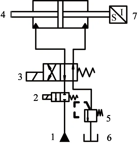
Fig.1 Schematic diagram of digital valve control servo system
The system consists of the following seven parts: 1 constant-voltage source; 2 high speed switch type digital valve; 3 electromagnetic directional valve; 4 hydraulic cylinder; 5 relief valve; 6 oil tank; 7 displacement sensor. In this diagram, the combination of digital valve 2 and electromagnetic directional valve 3 can take the place of servo valve, which control the hydraulic cylinder. Digital valve controls the oil flow and the electromagnetic valve controls the direction of oil. Relief valve controls the back pressure of the load system. The displacement sensor can measure the displacement of hydraulic cylinder, which constitutes a closed-loop position control system. This system can achieve precise position control of the hydraulic cylinder.
2 Modeling of digital valve control servo system
2.1 Modeling of the high speed switch type digital valve
In the working process, the digital valve element will be affected by four types of forces, the Fh(hydraulic pressure force), the Ff(flow force), the Fm(electromagnetic force) and Fk(spring force). The force of the digital valve element is shown in Fig.2.
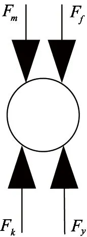
Fig.2 Force diagram of the high speed switch type digital valve
The equivalent circuit diagram of the digital valve is shown in Fig.3.
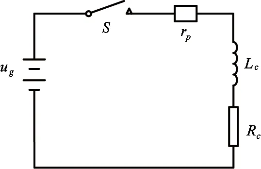
Fig.3 The equivalent circuit diagram
By analyzing this diagram, the exciting coil voltage balance equation in digital valve is

(1)
where, ugis the signal voltage of amplifier (V), Kuis the gain of amplifier, Rcis the resistance of control coil (Ω), rpis the internal resistance of amplifier (Ω), Lcis the inductance of control coil (H) and icis the electric current of control coil(A).
The DC solenoid electromagnetic force of the digital valve is generated in steady state:
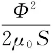
(2)
where, μ0is the permeability of vacuum(N/A2), S is the cross-sectional area of work air gap (m2), Kfis the magnetic leakage factor, b is the length of work air gap(m), N is the number of coil and i is the electromagnet current (A).
This equation is simplified by the Taylor series and the second order infinitesimal quantity, is omitted
Fm=Kmii-Kmxx
(3)
where,
(4)
and Kmiis the electromagnetic force variation coefficient caused by the coil electric current change.
(5)
and Kmxis the electromagnetic force variation coefficient caused by the valve element displacement change.
The flow force of the valve element is
Ff=2CvCdWΔpcosθ
(6)where, Cvis the velocity coefficient, usually 0.95~0.98, Cdis the flux coefficient of valve port, W is the area-grads(m), Δp is the pressure drop of valve port(Pa) and θ is the angle of jet flow(°).
This equation is simplified by the Taylor series and the second order infinitesimal quantity is omitted:
Ff=-Kfxx+KfpP
(7)
where,
(8)
here Kfxis the liquid force variation coefficient caused by the valve element displacement change.
Where,
(9)
and Kfpis the liquid force variation coefficient caused by the pressure difference.
In the work schedule, the force balance equation of valve element is

(10)
where, m is the mass of ball value and pushrod(kg), B is the viscous damping coefficient (N/(m/s)), K is the spring stiffness(N/m), x0is the precompressed spring length(m) and Flis the fluid force of valve element(N).
The flow which passes the high speed switch type digital valve port is
(11)
where, Cdis the flow coefficient of ball valve port, A is the valve port area (m2), Δp is the pressure drop of valve port(Pa), ρ is the oil density(kg/m3).
Eqs(1), (3), (7) and (10) take Laplace transform:
KuUg=(Rc+rp)Ic+LcIcs
(12)
Fm=KmiI-KmxX
(13)
Ff=-KfxX+KfpP
(14)
Fm=mXvs2+BXvs1+K(X0+X)+Fl
(15)
Assuming:

(16)

(17)

(18)
where, ωcis the coil angular frequency(rad/s), ω is the hydraulic inherent frequency(rad/s), ζ is the hydraulic damping ratio and k=K+Kfx+Kmx(N/m) is the synthetic stiffness.
In conclusion, the high speed switch type digital valve block diagram is shown in Fig.4.
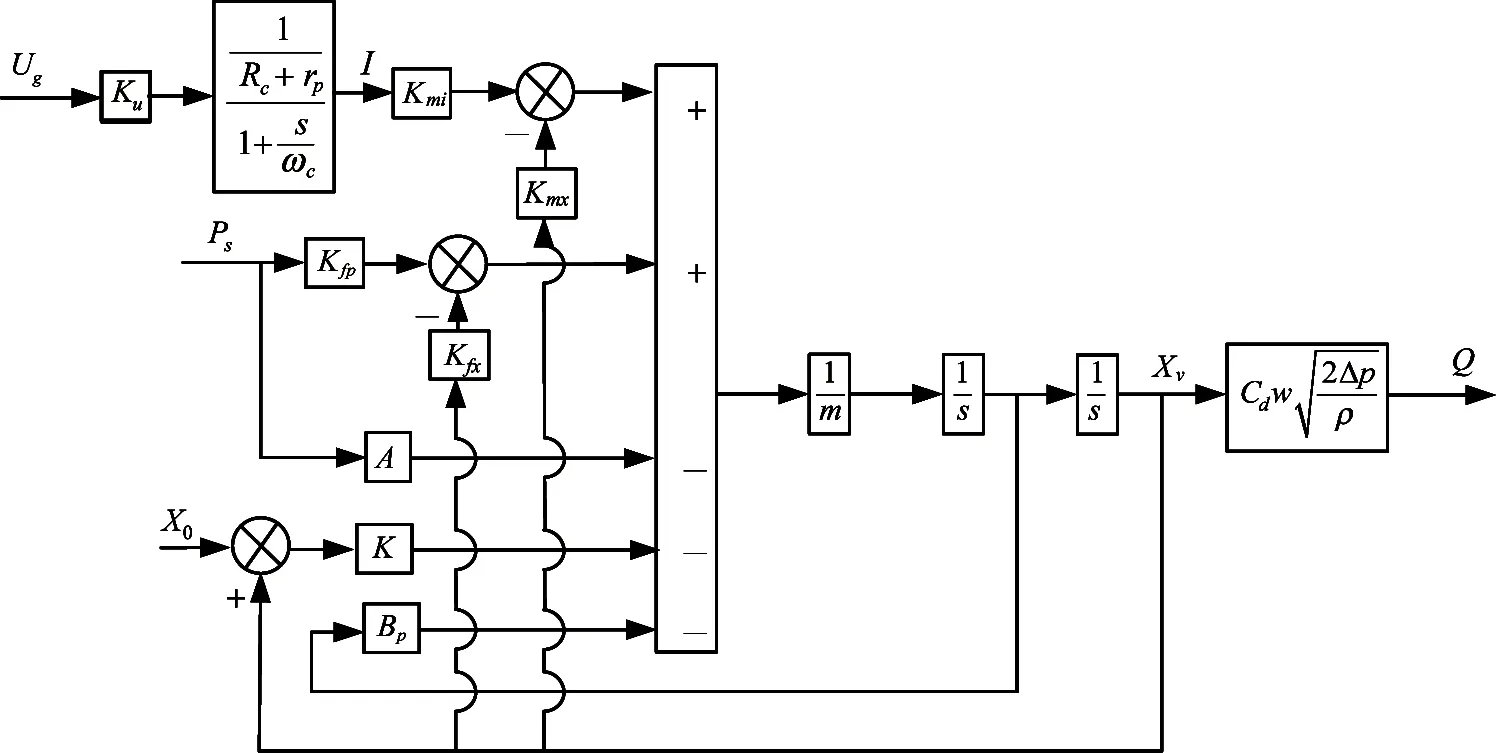
Fig.4 The high-speed switch type digital valve control diagram
2.2 Modeling of the electromagnetic valve and hydraulic cylinder
Since the inherent frequency of electromagnetic directional valve is close to the hydraulic inherent frequency, it is simplified into the second order oscillation section.
(19)
where, Ugis the voltage of reversing valve(V), Xvis the displacement of reversing valve(m), Kvis the enlarged coefficients of reversing valve, ωvhis the inherent frequency of reversing valve(rad/s) and ζvhis the damping ratio of reversing valve.
The electromagnetic valve for pressure and flow equation is
QL=KqXv-KcPL
(20)
where, QLis the load flow of electromagnetic valve (m3/s), Kqis the flow gain coefficient of electromagnetic value (m2/s),Kcis the valve flow and pressure coefficient ((m3/s)/Pa) and PLis the load pressure(Pa).
The continuity equation of the hydraulic cylinder is

(21)
where, APis the effective area of the hydraulic cylinder piston(m2), Ctpis the total leakage coefficient of hydraulic cylinder((m3/s)/Pa), Vtis the total compressed volume of the hydraulic cylinder (m3), βeis the elastic modulus of effective volume (Pa) and ypis the piston rod displacement (m).
The force balance equation of the hydraulic cylinder is
ApPL=mts2Xp+BpsXp+KXp+FL
(22)
where, mtis the mass of the piston and the load equivalent to the piston(kg), Bpis the viscous damping coefficient of piston and the load(N/(m/s)), K is the spring stiffness of load(N/m) and FLis external load force(N).
From the above equations, omitting the elastic load and hydraulic cylinder leakage, the high-speed on-off digital valve control cylinder system block diagram is shown in Fig.5.
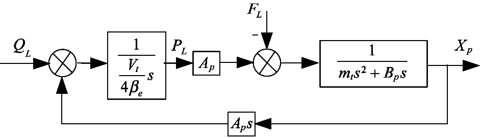
Fig.5 Digital valve control cylinder system control diagram
Finally, the position closed-loop control block diagram of the electro-hydraulic digital valve control servo cylinder system is shown in Fig.6.

Fig.6 Digital servo closed-loop position control diagram
3 Design of CMAC-PID adaptive controller
CMAC network is different from conventional neural networks. From the viewpoint of individual neuron, its input-output relationship is linear. However, the overall structure of CMAC network is nonlinear. The CMAC network has a strong nonlinear mapping and generalization ability for real-time control of complex nonlinear dynamic application.
3.1 CMAC network structure
A typical CMAC network consists of an input space, a storage space and an output space. The network realizes the mapping from input space to storage space and storage space to output space.
The dimensions of input space are determined by the dimensions of the controlled model. Each input vector from input space is mapped to the storage space (A) in accordance to certain rules.
The storage space(A) is divided into virtual storage space(AC) and practical storage space(AP). Each input vector has the corresponding memory spaces, the number of which is C(generalization parameter). The process of actual learning may not contain all the input state of the system, so the information of AC should be mapped to AP according to a certain coding method, and right value is stored in the corresponding address of AP.
In the output layer, the total output of the network is the plus of the C memory cells’ weight (w) in the actual storage space AP:
(23)
The CMAC network structure is shown in Fig.7.
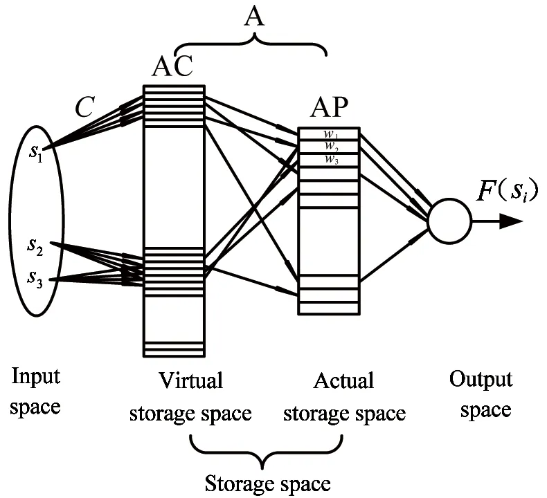
Fig.7 Structure of CMAC neural network
Fig.7 shows that the network output is a linear combination of weights, while the network is addressed by linear change and random compression. So the CMAC network has the ability to map nonlinear functions.
3.2 CMAC network working principle
On the basis of the CMAC network structure, the working principle of the whole network is divided into the following steps:
Step 1 Quantification of input vector
Since the input space is one-dimensional, the quantification method can be described as:
Input s∈[a,b], M is the quantification stages, and u is the quantification value.
Δu=(b-a)/(M-1)
(24)
u(i)=a+Δu*(i-1) (i=1,2,…,M)
(25)
Step 2 The input space to the virtual storage space
After the quantification, the input value requires to be mapped to the virtual memory space. According to the CMAC network principles, an input value could and should be used to activate C memory cells in the virtual storage space simultaneously.
Step 3 Virtual mapping to the actual mapping
The mapping from the virtual storage space(AC) to the actual storage space(AP) commonly uses hash coding method. Since the input space of this article is one-dimensional and small, one to one mapping is used instead of hash mapping in coding.
Step 4 Learning algorithm
CMAC network uses a supervised learning method, which requires the presence of a tutor outside the network. The tutor provides desired output for the neural network according to their experience and knowledge. The error between the CMAC output value and the desired output value is used to adjust the weights in the C memory cells. Adjusting the weights is used to reduce errors and to approximate to the desired output.
CMAC network commonly uses δ learning rule to adjust the weights, and δ learning rule can be called least mean square(LMS) rule. Its objective of adjusting weights is to get the least mean square, which can be described as

(26)
e(t)=r(t)-y(t)
(27)
where, r(t) is the given signal, and y(t) is the feedback signal. According to the gradient descent method, the CMAC network weights adjusting formula is

(28)
wj(t)=wj(t-1)+Δwj(t)+α(wj(t-1) -wj(t-2))
(29)
(30)
where, η is the learning rate, η∈(0,1), α is the momentum factor, α∈(0,1). Simultaneously, the selection of quantification stages M and generalization parameter C is also very important. M determines the CMAC network’s approximation accuracy, which increases with the increasing of the quantification levels. But the required memory space will be greater with the increasing of M. Generally, for the generalization parameter C, quantification stages M are 10 times more than parameter C. Only in this way, can the CMAC network achieve a better approximation accuracy of nonlinear function.
3.3 Design of CMAC-PID compound controller
In this paper, traditional PID is used as feedback control, in order to ensure the stability of the system, CMAC network is used as feed-forward control, in order to improve the control accuracy of the system. The plus of PID output and the CMAC network output is the total output. And the total output controls the controlled object. The compound control structure is shown in Fig.8.

Fig.8 Structure of CMAC-PID compound control for digital valve control system
According to the digital valve control servo cylinder system block diagram and CMAC-PID compound control block diagram, a CMAC-PID compound control simulation model is built in Matlab / Simulink, the simulation parameters of this system are set as Table 1.
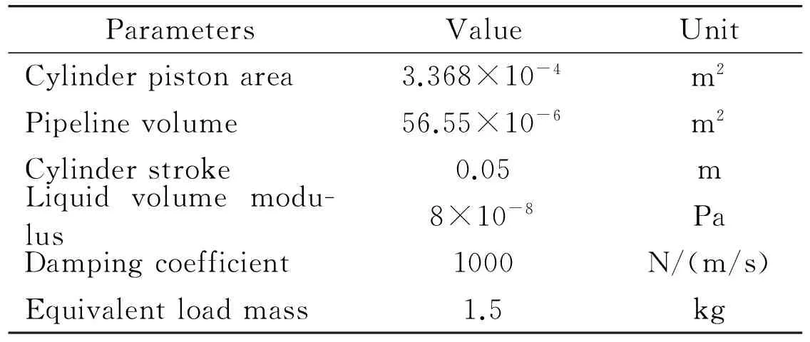
Table 1 Simulation parameters of digital valve control servo system
3.4 Simulation study
The given position step signal is 0.02m, oil pressure is 7MPa, the operating frequency is 10Hz, according to the system parameters to determine the PID parameters: Kp=150, Ki=0, Kd=0.02. To prevent
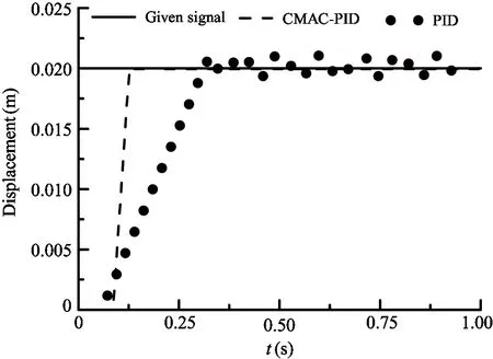
Fig.9 Contrast of the step response curve
over-learning phenomenon, learning rate is set as 0.001. The traditional PID control simulation curve and the CMAC-PID compound control simulation curve are shown in Fig.9~Fig.13.
Fig.9~Fig.13 show that after using CMAC-PID compound control method, the transient and steady state performance are improved, which proves that this proposed control algorithm is effective.

Fig.10 Contrast of the error curve

Fig.11 Contrast of the sine response curve
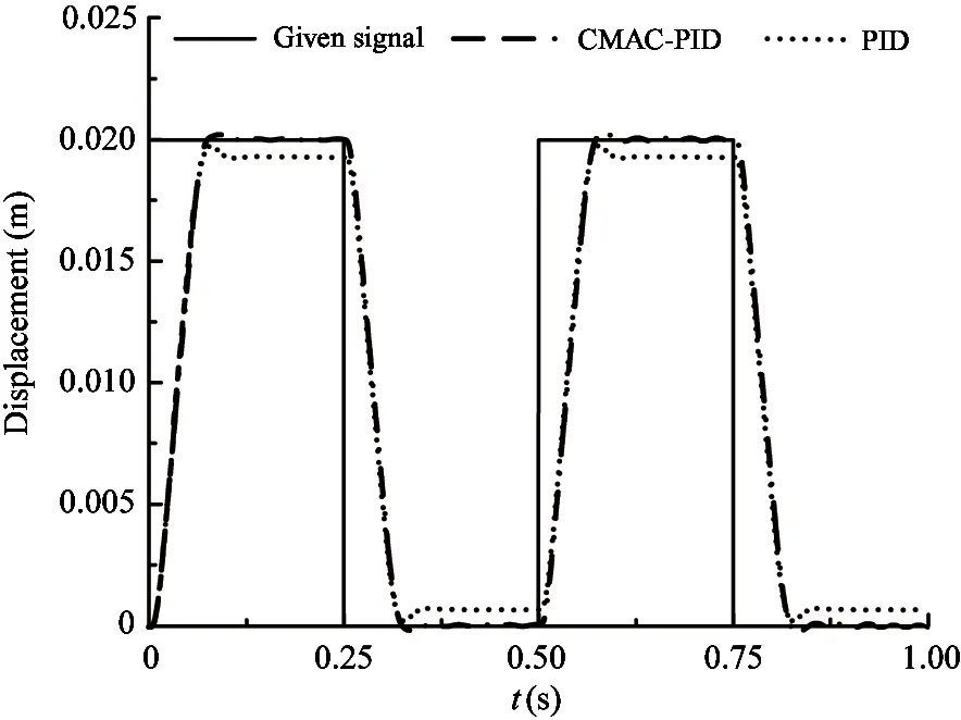
Fig.12 Contrast of the square-wave response curve
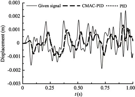
Fig.13 Contrast of the random signal response curve
4 Experiment study
4.1 Experiment scheme
An experiment is conducted in the electro-hydraulic digital valve control servo system test bench as shown in Fig.14.

Fig.14 Electro-hydraulic digital valve control servo system experiment bench
The experiment scheme is shown in Fig.15. The Host PC controls the system through the Matlab/Simulink software, then the control program runs in the Slave PC by the xPCTarget. The Slave PC outputs the signal by controlling cards. The card ACL-6126 and PCL-731 control the high-speed switch type digital valve, and the card PCL-731 controls the solenoid directional valve. Hydraulic components output the signal to the DAQ Card PCL-1716 through the sensors, and the PCL-1716 transmits the signal to the Slave PC. This experiment scheme achieves precise control of the hydraulic cylinder position.

Fig.15 Experiment scheme
Card PCI-1716 is a multi-channel high resolution DAQ Card of 16-bit. Card ACL-6126 is an analog control card with 6 channels and 12-bit resolution. The card can output voltage signals. Card PCL-731 provides 48 digital output channels. The parameters of main control components and sensors in this system are shown in the following tables.
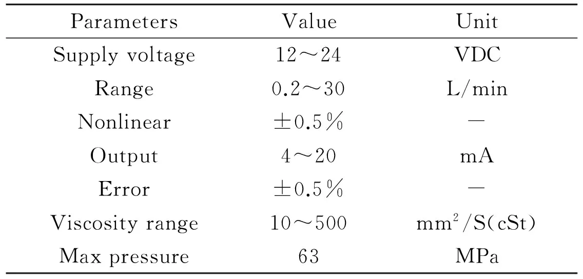
Table 2 Parameters of the high-speed switch type digital valve

Table 3 Parameters of displacement sensor

Table 4 Parameters of flow sensor
4.2 Traditional PID as compared with CMAC-PID in control performance
In this experiment, the supply oil pressure is 7Mpa, rated flow is 15L/min, the back pressure of the overflow valve is 3Mpa and the given signal is 0.02m step signal. The parameters of PID: Kp=170, Ki=0, Kd=0.1. This experiment is performed in different carrier frequencies of 1Hz, 10Hz and 50Hz respectively. The three groups of response curve under two different control strategies are shown in Fig.16.
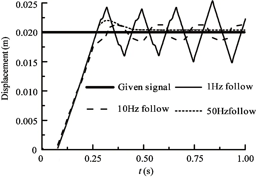
(a) Traditional PID
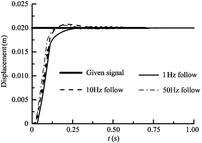
(b) CMAC -PID
The given signals are sine, square-wave and random. The amplitude of these signals is 0.02m. The frequency of sine and square-wave signals is 2Hz. The parameters of PID: Kp=170, Ki=0, Kd=0.1. This experiment is done with carrier frequency of 10Hz. The response curves under two different control strategies are shown in Fig.17~Fig.19.
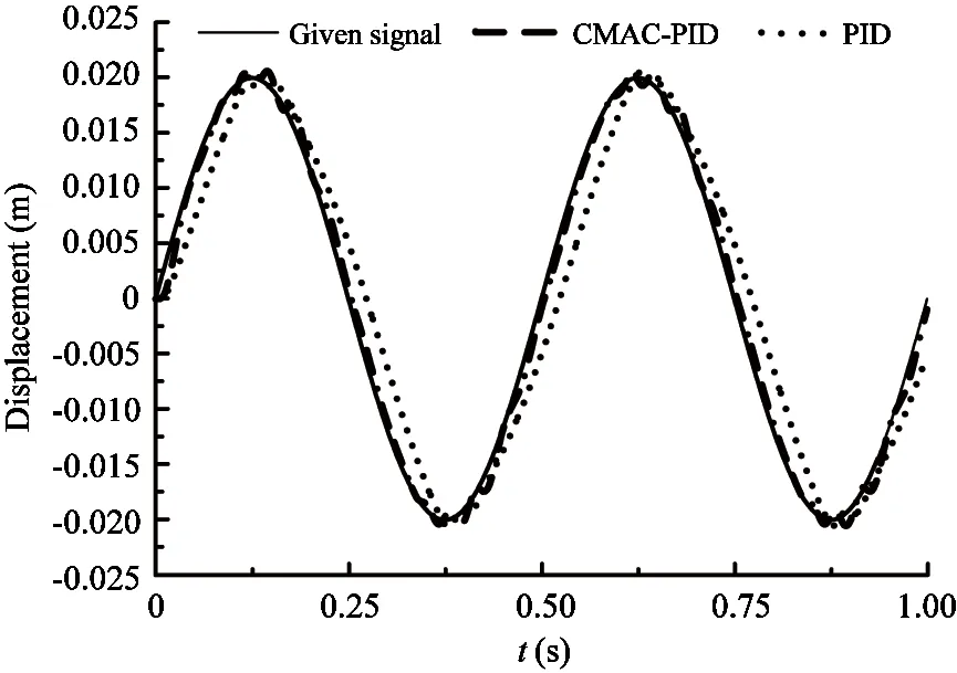
Fig.17 Response curve comparison for input signals of sine-wave
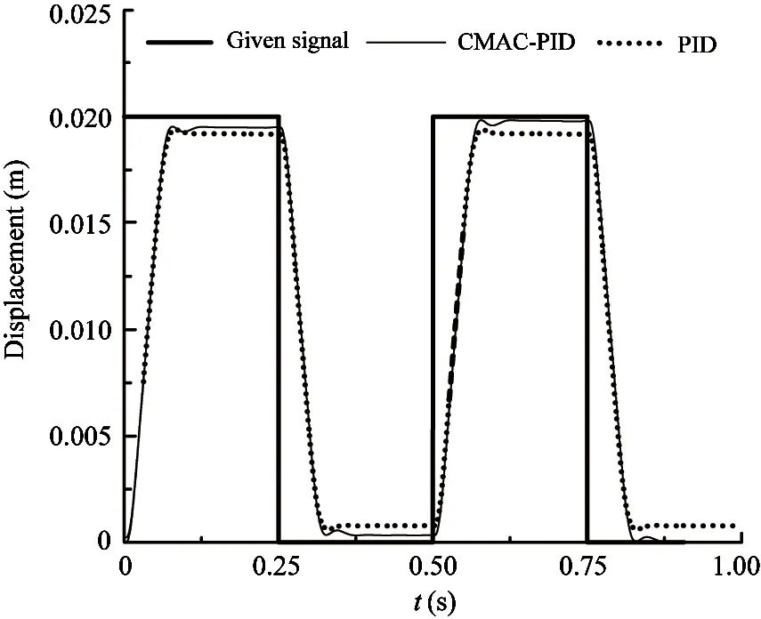
Fig.18 Response curve comparison for input signals of square-wave
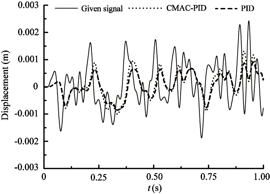
Fig.19 Response curve comparison for input signals of random signals
Comparison in Fig.16~Fig.19 proves that the simulation model of this system is effective which can reflect the basic characteristic of the system. It can be seen from Fig.16(a) and Fig.16(b) that the control precision under steady state and the transient response are improved with the increase of carrier frequency. Through the experiment and Fig.16~Fig.19, it is known that the transient response characteristics improve significantly, delaying time, rising time and adjusting time of the responses for the step signal, sine signal, square-wave signal and random signal decrease remarkably under the control of CMAC-PID. The simulation and the experiment prove the effectiveness of the CMAC-PID compound control method.
5 Conclusion
In this paper, the electro-hydraulic digital valve control servo system is conducted using one digital valve and one directional valve. Also the simulation model of the system and the CMAC-PID compound control method are established. The following can be concluded from the simulation and experiment:
The accuracy of this system and the transient response characteristics increase as the digital valve working frequency increases. When the carrier frequency is 50Hz, this servo system can realize the stability control and the stable precision error is controlled within 0.7mm.
Compared with traditional PID, the transient response characteristics increase significantly, the response time decreases by almost 25% under different carrier frequency using the CMAC-PID controller.
Compared with the traditional PID, the stable precision improves significantly and the stable precision error is controlled within 0.1mm using the CMAC-PID controller.
[ 1] Linjama M, Laamanen A, Vilenius M. Is it time for digital hydraulics. In: Proceedings of the 8th Scandinavian International Conference on Fluid Power, Tampere, Finland, 2003. 347-356
[ 2] Xu Y Z, Chen W N. Hydraulic high-speed on-off valve and Its application on industries. Hydraulics Pneumatics & Seals, 2012, 32(1): 72-77
[ 3] Ding F, Yao J D, Da J, et al. Advances on high-speed on-off valves. Chinese Journal of Construction Machinery, 2011, 9(3): 351-358(In Chinese)
[ 4] Wang W W, Song J, Li L, et al. High speed on-off solenoid valve with proportional control based on high frequency PWM control. Journal of Tsinghua University(Science and Technology), 2011, 51(5): 715-719(In Chinese)
[ 5] Paloniitty M, Linjama M, Huhtala K. Equal coded digital hydraulic valve system-improving tracking control with pulse frequency modulation. Procedia Engineering, 2015, 106: 83-91
[ 6] He J, Yuan S Y. High-speed on/off valve hydraulic position control system based on DSP. China Mechanical Engineering, 2010, 21(24): 2929-2931(In Chinese)
[ 7] Gao Q H, Liu Z H, Niu H L, et al. Position control of hydraulic cylinder controlled by high-speed on-off valve. China Mechanical Engineering, 2015,25(20): 2775-2781(In Chinese)
[ 8] He J, Yuan S Y. H∞Control for hydraulic cylinder position control system based on high-speed on/off value. Control Engineering of China, 2008, 15 (S1): 79-84
[ 9] Lin Y. Research and Digital Simulation of High speed on/off Valve:[M.S Dissertation]. Wuhan: School of Mechanical and Electronic Engineering, Wuhan University of Technology, 2005. 9-18(In Chinese)
[10] Meng D Y, Tao G L, Li A M, et al. Adaptive robust control of pneumatic cylinders using fast switching on/off solenoid valves. Journal of Mechanical Engineering, 2015, 50(10): 180-188
[11] Liu J K. Advanced PID Control MATLAB Simulation. Beijing: Electronic Industry Press, 2004. 183-193
[12] Zhang Z X. Neural Network Control and MATLAB Simulation. Harbin: Harbin Industrial University Press,2011. 165-186(In Chinese)
[13] Liu D, Jiang J, Zhang D W. Simulation study of controlling DC motor of based on CMAC neural network PID control algorithm. Instrumentation Technology, 2014, 1: 45-49
[14] Qian X S, Li J, Lei P F. The application of CMAC-PID parallel control algorithm in electro-hydraulic servo system. Computer Measurement & Control, 2015,23(11): 3674-3681
[15] Jia C Y, Shan X Y, Cui Y C. Modeling and simulation of hydraulic roll bending system based on CMAC neural network and PID coupling control strategy. Journal of Iron and Steel Research, International, 2013, 20(10):17-22
[16] Rong Y R. Study of Controlling ZTS16 Electro-hydraulic Proportional Valve Based On CMAC-PID Compound control strategy:[M.S dissertation]. Changsha: College of Mechanical and Electrical Engineering, Central South University, 2010. 23-33(In Chinese)
[17] Li Q, Yuan R B, Yang H F. Study on hybrid control of pneumatic position servo system based on CMAC and PID. Fluid Power Transmission & Control, 2009, 5: 19-21
his Ph.D and M.S. degrees in Harbin Institute of Technology in 2013 and 2008, respectively.He also
his B.S. degree from Northeastern University in 2006. His research interests include the control of electro-hydraulic servo system, rehabilitation robot and environmental simulator.
10.3772/j.issn.1006-6748.2017.03.012
To whom correspondence should be addressed. E-mail: jyao@ysu.edu.cn Received on Mar. 12, 2017
Supported by the National Natural Science Foundation of China (No. 51505412) and the Independent Study Program for Young Teachers in Yanshan University (No. 14LGB004).
猜你喜欢
导航定位学报(2022年5期)2022-10-13
电影文学(2022年8期)2022-05-24
故事会(2022年7期)2022-04-03
小小说月刊(2022年1期)2022-02-07
山东陶瓷(2021年5期)2022-01-17
疯狂英语·新悦读(2020年10期)2020-10-31
苏州工艺美术职业技术学院学报(2020年1期)2020-07-20
疯狂英语·新悦读(2020年2期)2020-04-29
疯狂英语·读写版(2019年4期)2019-09-10
时代邮刊(2019年20期)2019-07-30
 High Technology Letters2017年3期
- High Technology Letters的其它文章
- Quantitative analysis of the performance of vector tracking algorithms①
- Application of linear active disturbance rejection control for photoelectric tracking system①
- Structure design of gradient hard coatings on YG8 and their residual stress analysis by ANSYS①
- ZnO whiskers growth on the surface of Sn9Zn/Cu solder joints in concentrator silicon solar cells solder layer①
- Characterizing big data analytics workloads on POWER8 SMT processors①
- A leveling mechanism for the platform based on booms-constraint control of aerial vehicle①