
Design and test of semi-feeding test-bed for peanut pod picking
2017-11-01 23:03HuZhichaoWangBingYuZhaoyangPengBaoliangZhangYanhuaTanke
农业工程学报 2017年17期
Hu Zhichao, Wang Bing, Yu Zhaoyang, Peng Baoliang, Zhang Yanhua, Tan Lüke
Design and test of semi-feeding test-bed for peanut pod picking
Hu Zhichao, Wang Bing, Yu Zhaoyang, Peng Baoliang, Zhang Yanhua, Tan Lüke
(Nanjing Research Institute of Agricultural Mechanization, Ministry of Agriculture, Nanjing 210014, China)
A semi-feeding test-bed was developed to study the working mechanism of the semi-feeding device for peanut-pod picking, and optimize its structure and working parameters. The test bed was mainly composed of a frame, an automatic feeding platform, a clamping-carrying device, a peanut pod picking device, a control system, sensors, a converter motor and a high-speed photography system, with many functions, such as key parameters adjustment and collection, process image acquisition, and plant fresh keeping. The main technical indexes of the test-bed were as follows: the pod-picking roller length was 500, 800, 1 000 mm, the roller diameter was 160, 200, 240 mm, the distance between the center of the back end of the roller and the clamping-carrying chain was 100-150 mm, the peanut pod picking device rotation rate was 200-1 000 r/min, the clamping-carrying chain velocity was 0.5-2.5 m/s. Based on the previous design, this paper mainly focused on the design and analysis of the pod-picking device, the automatic feeding platform, the control system, the clamping-carrying device and the fresh-keeping storage house and so on. Experiments on the plant-feeding number, the included angle between the chain and roll (hereinafter refers to briefly as the included angle), the power consumption, and the high-speed photography of pod picking were carried out by the semi-feeding test-bed, which had not been done previously. The results show that the plant-feeding number has a great effect on both the breakage rate and unpicked rate, while the included angle has a great effect on the unpicked rate, but a little effect on the breakage rate. When the picking roller are fully filled with plants at the smooth working stage, the larger the plant-feeding number is, the higher power consumption is. The high-speed photography experiment reveals the influence between the pod-picking blade and the peanut pods, the separation between pod and vine, and the internal mechanism. Overall, the test-bed can provide effective technical means for the further study on the mechanism of the pod-picking working.
crops; design; optimization; peanut; semi-feeding; pod-picking; power consumption; high-speed photography
0 Introduction
Compared with the full-feeding technology for peanut pod picking, the semi-feeding technology is mainly applied to the fresh peanut picking, with many advantages, such as the relatively mild picking force, the lower breakage rate, the lower power consumption, and the fresh seedlings complete recovering[1-3]. The semi-feeding device is the core component of a semi-feeding harvester or a pod-picking machine. It adopts a seedling-clamping mechanism and an opposite rotating double-roller with a certain angle configuration[4-5]. When peanut plants are clamped and transported through the pod-picking mechanism, the separation of pod and seedling is completed from bottom to top by the continuous high-speed rotation at opposite directions of two sets of pod picking blades[6]. Therefore, the pod-picking device has an important influence on the performance of the harvester, such as the breakage rate and the unpicked rate.
Nowadays, researches worldwide on semi-feeding technology for peanut picking are few, and mainly focus on equipment development[7-14]and experimental research. Wang Dongwei et al.[15]optimized the structure and the movement parameters of peanut picking device with curve-surface double rollers; Su Zhan et al.[16-17]developed a small semi-feeding breeding device with double rolls for peanut picking and carried out experiments on the structure and parameters. Wang Xiaoyan et al.[1-4]designed a semi-feeding test-bed for peanut picking, carried out the parameter optimization test, and obtained the optimum combination of parameters; Lü Xiaorong et al.[18]utilized virtual simulation methods to test the performance of the peanut pod picker under different working conditions. Hu Zhichao et al.[8,13,19-20]developed the semi-feeding two and four rowscombine harvesters for peanut and peanut semi-feeding picker. Moreover, he carried out a great deal of researches on semi-feeding technology for peanut pod picking to reduce the both rates of breakage and unpicked, to optimize the structural design, the structural parameters, the kinematic parameters, the pod-picking mechanism and so on[5-6,8,21-22]. So far, profound study on semi-feeding technology for peanut pod picking has not been found abroad by retrieving the foreign document of peanut mechanized harvesting technology research[23-27].
The above studies just focused on the design and partial parameters optimization of semi-feeding device for peanut pod picking, because of the limited technical means. The relationships between variables, such as the plant-feeding number, the included angle, and operation quality have not been studied. The specific interaction between pod-picking blade and pods has not been made clear yet, which is crucial to reveal the mechanism of pods breakage and pods unpicked. The power consumption of the peanut pod picking device under complicated conditions has not been measured, which is of great significance for energy-saving, working life prediction and design of the device. Therefore, based on the previous researches, the semi-feeding test-bed with testing, adjusting and image collecting functions was developed. Briefly, experiments on the power consumption, parameters and high-speed photography carried out by the semi-feeding test-bed will provide a theoretical basis for the semi-feeding device for peanut-pod picking.
1 Development of the semi-feeding test-bed
1.1 Overall design
On the basis of the existing semi-feeding test-bed for peanut pod picking[5], the development scheme of the semi-feeding test-bed was designed (Fig.1). An automatic feeding platform, a control system, a test system, a parameter regulating system and a fresh-keeping storage house were developed, and a high-speed photography system was selected. All of them were integrated into the former test-bed made by the research group.

Fig.1 Development scheme of semi-feeding test-bed for peanut pod picking
Based on the above, the semi-feeding test-bed was developed. The key technical indexes of the test-bed were as follows: The pod-picking roller length was 500, 800, 1 000 mm; The double rollers center distance was 170-220 mm; The rollers diameter was 160, 200, 240 mm; Distance between the center of the front end of the roller and the clamping chain was 200-300 mm; Distance between the center of the back end of the roller and the clamping chain was 100-150 mm; Roller rotation rate was 200-1 000 r/min; The clamping chain velocity was 0.5-2.5 m/s; High speed camera version: FastecHispe5; Temperature range of the fresh-keeping storage house was 0-15 ℃.
The designed automatic feeding platform could be used to simulate the working conditions of the prior level of the conveying component during the combined harvesting operation. The three converter motors were respectively connected to the automatic feeding platform, the clamping-carrying device and the peanut pod-picking device. Each motor was attached with a speed sensor. Meanwhile, a torque sensor was mounted on the peanut pod picking device. All the sensors were connected with the control system to realize the independent regulation of the speed of the three moving devices and the torque test. The peanut pod picking device was arranged on an independent movable frame, and the movable frame was connected with a fixed frame, so that the integral adjustment of the picking device and the independent change and step-less adjustment of the picking roller could be realized. The high speed photography camera could be fixed at the end of the entry, the middle of the fracture section and the end of the exit, of the rollers, which was convenient to record the interaction of the pod-picking blades and peanut plants, analyze the separation of pod and seedling, and reveal the influence mechanism of operation quality.
Our research group had carefully designed and researched the peanut pod-picking rollers in the previous study. Therefore, this paper mainly focused on the design and analysis of the automatic feeding platform, clamping- carrying device and control system.
1.2 Design of the peanut pod-picking roller
According to the previous research result[5], the structure form and structure parameters of the peanut pod-picking roller were set as follows: the picking roller and the clamping chain were configured at a certain angle; the form of pod-picking blade was arc type; the blade numbers of one roller were four; the roller adopted the structure of “moving sleeve static” to prevent the film from winding. In order to study the influence on operation quality by different parameters of the roller, various types of rollers were designed, and double rolls center distance and the roller angle could be adjusted.
1.3 Automatic feeding platform design
1.3.1 Overall design
The structure of the automatic feeding platform was shown in Fig.2. The automatic feeding platform adopted the horizontal belt conveyor with a closed loop. When the roller rotated, the belt kept a continuous annular movement by friction. The peanut plants were continuously fed into the feeding frame and fall to the conveyor belt. Under the influence of the belt friction, the plants were transported along with the conveyor belt. In order to improve the adaptability of feeding platform, the overall angle of the feeding platform was adjustable. As shown in Fig.2, the main parameters of the automatic feeding platform were as follows: Conveying length=1 500 mm; Conveying width=470 mm; Conveying velocity=0.5-2.5 m/s; Drive roller size is200 mm×1 500 mm; Conveying angle=0-10°; Feeding frame height=230 mm.

1.Active roller 2.Conveyer belt 3.Peanut plant 4.Tension roller 5.Lower roller 6.Frame 7.Feeding frame
1.3.2 Motion analysis
As shown in Fig.3, the quality of the peanut plant was assumed to be, the initial speed of the plants arriving at the conveyor belt was0(0horizontal contained angle was). Suppose that the conveyor length was, the dip angle was, and the belt velocity wasWhen the plants were about to move to the conveyor belt, the velocity of the plants relative to the conveyor belt wasV, the projection ofVin the conveying direction and vertical direction of the conveyor belt wasVandVrespectively, then:


Note:was the weight of the feeding peanut plant, g;0was the initial speed of the plants arriving at the conveyor belt, m·s-1;was0horizontal contained angle (°);awas the acceleration of the plants reached on the conveyor belt, m·s-²;was the friction of the plants reached on the conveyor belt, N;was the supporting force of the plants reached on the conveyor belt, N;was gravitational acceleration,=9.81 m·s-².
Fig.3 Feeding movement analysis
According to Formula (1) and (2), whenVwas not equal to zero, there must be a relative slip between the plants and the conveyor belt. The relative slipping process was exactly the acceleration process, while theVresulted in the plants shocking on the conveyor belt. The above conditions aggravated the wear of the working surface of the conveyor belt and reduced the strength. The force analysis of the plants during acceleration was shown in Fig.3, the relative sliding acceleration of the plants could be obtained according to the force balance condition, such as Formula (3). The distance that the plants completed the acceleration process was0,and the plants were unstable during the acceleration process.

Wherewas friction coefficient between plant and conveyor belt;awas the acceleration of the plants reached on the conveyor belt, m/s²;was gravitational acceleration,= 9.81 m/s2.
1.3.3 Main parameters optimization
As shown in Fig.4, the plants should have maintained the same posture when they entered the clamping-carrying chain from the conveyor. However, as we had known from 1.3.2, there was a relative slippage of the plants at the conveyor table, which might cause the peanut plants to tilt on the conveyor table. The inclination of the plants was related to the speed of entry into the conveyor belt (determined by) and the conveying distanceTherefore, the effect of plant inclination should be considered to improve the join effect of the plants from the conveyor belt into the clamping-carrying chain when designingand.
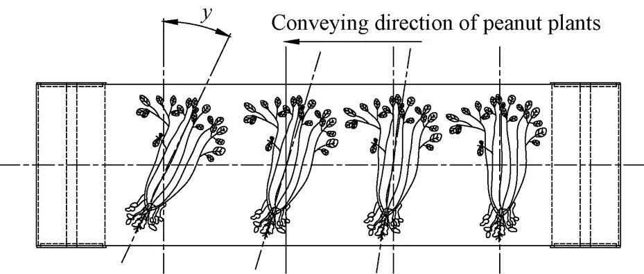
Note: y was plants inclination angle of arrival at the feeding entrance, (°).
The definition of objective function:=(,). The smaller thewas, the higher the feeding quality was. The test of each set of parameters was carried out 10 times, taking the average value.
andwere optimized by folio optimum seeking method, as shown in Fig.5. According to previous tests, the range ofchanged from 150 to 330 mm, and the range ofchanged from 900 to 1 700 mm.was fixed at 230 mm firstly, and the1point was found as the better one by 0.618 point method,=1 500 mm. Then the upper and lower folded,was fixed at 1 300 mm, the1point was found as the better one by 0.618 point method. The1was found better than the1point by comparing the two points, so the lower half was abandoned. Then the upper and lower of remaining part folded.was fixed at 1 500 mm, the1was better also. Therefore, the1point was what we want.was 230 mm andwas 1 500 mm.
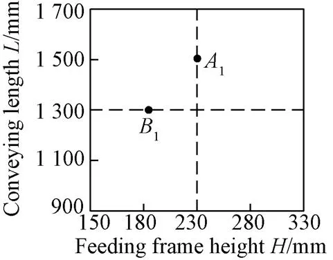
Fig.5 Folding optimum method
1.4 Design of clamping-carrying device
1.4.1 Overall design
The structure of the clamping-carrying device was shown in Fig.6. The triangular area was formed among the clamping chain, the conveyor belt and the pressure plate, which was called “vine merging zone”. The plants were grabbed by the clamping chain of the “vine merging zone” and clamped and rearward conveyed at the clamping point position. The following conditions should be met when designing the clamping-carrying device: First, feeding, grabbing, clamping and conveying were smooth and reliable; Second, after the plants were clamped and transported into the peanut pod picking device, broken stems, blocking and sliding vines should not appear; Third, the device should be able to adapt to changes of plant moisture content and thickness. The main factors affecting the clamping-carrying performance were clamping chain type, geometric parameters of the triangle and the velocity of the clamping chain.

1.Drive sprocket 2.Clamping-carrying chain 3.Clamping device 4.Automatic tensioning device 5.Driven sprocket 6.Clamping point 7.Triangular area
1.4.2 Design of the triangular area
The key design parameters of the triangular area were shown in Fig.6.awas determined by the current peanut agronomic and biological characteristics, and the plant-feeding numbers, the design value was equal to 350 mm. The two parametersandbinterrelated. The larger thewas, the less thebwas, and the clamping point would move forward. The less thewas, the larger thebwas, the clamping point would move backward. In the “vine merging zone”, the clamping chain pressed the plants in the vertical direction, and pushed the plants forward in the horizontal direction. At the feeding entrance, the vine merging time should be as short as possible, while the feeding plants should be transported backward as soon as possible. By comparing and analyzing the two parametersandb, the larger thewas, the less thebwas, the shorter the retention time was, when the plants enter the “vine merging zone”. Through the test, the parameters could be set as:=85°,b=130 mm.
1.4.3 Parameter design of toothed chain
The toothed chain was used as the conveyor chain of the test-bed. The experiment showed that the addendum angle and the tooth height had obvious influence on the probability of broken stems, blocking and sliding vines. Therefore, the critical parameters of the toothed chain could be selected by using the evaluation index of the numbers of the clamping failures, in details: The toothed chain pitchwas set as 33 mm. Three series of addendum angle were 60°, 70°, and 90°. Two series of tooth height were 10, 15 mm. The influence of the addendum angle and the tooth height on the clamping performance was investigated by the bench test. Six different parameters combinations were used for the bench test. The results showed that the number of toothed chain failures was the largest when the addendum angle was 60° and the tooth height was 15 mm; The number was the least when the addendum angle was 90° and the tooth height was 10 mm. Therefore, the addendum angle 90° and the tooth height 10 mm were selected, which could effectively guarantee the clamping-carrying device working smoothly and reliably.
As shown in Fig.7, the movement of the clamping-carrying chain grabbing the plants was analyzed. In addition, the velocity resolution of the random pointin the grabbing segment was carried out. When thevalue (mentioned above) was determined, both conveyor belt forward velocity and clamping chain velocity should meet Formula 4 in order to guarantee the peanut plants grabbed in the triangle area and delivered them back in time.

Whereawas the linear velocity of the point, m/s;swas the forward velocity of the conveyor belt, m/s;was the angle between the clamping chain and the conveyor belt, (°).
Note:awas the linear velocity of the point, m·s-1;swas the forward velocity of the conveyor belt, m·s-1.
Fig.7 Movement analysis of clamping-carrying chain grabbing plant
1.5 Other systems design
1.5.1 Control system design
The controller of the control system was SIEMENS S71200PLC, and the driver was G120C with Ethernet communication. The implementation motor was SIEMENS BEIDE, a three-phase asynchronous motor. The control panel was made of SIEMENS KTP, a delicate touch screen with Ethernet interface. The communication system adopted SIEMENS PN protocol and PROFINET interface. The control system was shown in Fig.8.

1.Control panel 2.G120C driver 3.S71200PLC 4.Circuit breaker 5.Air switch 6.Torque sensor receiving terminal 7.Relay 8.Power supply 9.Transformer
1.5.2 Fresh-keeping storage house design
In order to prolong the test period, prevent the peanut from spoiling that would influence the test result, a kind of fresh-keeping storage house was designed to keep peanut plant fresh. The fresh-keeping storage house parameters were as follows: the temperature range was 0-15 ℃; the compressor refrigerating capacity was 5 kW; the temperature and humidity were controlled by microcomputer; the green cryogen was adopted; the dimensions of the storage house was 3 000 mm×2 000 mm×2 000 mm.
2 Experiment study
2.1 Experiment purposes
Previously we had done a part of the studies on semi-feeding device for peanut pod picking[2,5,6,21]. This paper mainly studied on the effect of the two factors, the plant-feeding number and the included angle, which was not covered in previous study, on the working index upon the semi-feeding test-bed. A solid ground for the further research of the multiple parameters optimization test on the semi-feeding test bed could be provided by studying the influence of the above two factors on the operation index and combining with the previous research. Moreover, the influence of the plant-feeding number on power consumption was carried out, which provided the basis for the optimization design of the peanut pod-picking roller. The high-speed photography test was also carried out to reveal the process of pod-picking blade and pods.
2.2 Test parameters and materials
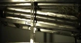
Tests was carried out by the test-bed mention above, as shown in the Fig.9. The other test parameters were set during the test. The speed of the pod-picking roller was 500 r/min. The length of the pod-picking roller was 1 300 mm. The velocity of the clamping-carrying chain was 1 m/s. The velocity of the automatic feeding platform was 80 mm/s. The double rolls center distance was 200 mm. When the power consumption test was carried out, the included angle was set as 15°. When the single factor test about the plant-feeding number was carried out, the included angle was set as 15°. When the single factor test about the included angle was carried out, the plant-feeding number was set as 12 plants/s. The peanut varieties were Yuhua No.7, Haihua No.1, Zhanyou 75, and Tianfu No. 9.

1.Clamping-carrying device 2.Peanut pod-picking device 3.Frame 4.High-speed photography system 5.Test and analysis system 6.Light source 7.Automatic feeding platform 8.Control cabinet 9.Speed sensor 10.Torque sensor 11.Converter motor 12.Manipulation system
2.3 Test index
1)Power consumption
The power consumption of the pod-picking roller referred to the average power consumption at smooth working stage when the pod-picking roller was completely filled with plants.

Wherewas the power consumption of the pod-picking roller, kW;was the real-time speed of the roller by the sensors, r/min;was the torque of the roller by the sensors, N·m.
2) Unpicked rate

Where1was unpicked rate, %;1was weight of the plants been not picked up by the peanut pod-picking roller, g;2was gross weight of harvested pods by the peanut pod-picking roller, g.
3) Breakage rate
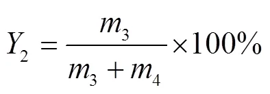
Where2was breakage rate, %;3was weight of broken pods, g;4was weight of good pods, g.
2.4 Power consumption test
The quadratic fitting and regression analysis of the test results (shown in Table 1) were carried out by SPSS. The relationship between the plant-feeding number and the power consumption was a highly positive correlation, and the quadratic fitting effect was good.<0.01 (Significance level) showed that the influence of the plant-feeding number on power consumption was very significant. As seen in Table 1, when the roller was fully filled with plants at smooth working stage, with the increase of the plant-feeding number, the power consumption increased. Take Yuhua No.7 for example. The power consumption of 24 plants/s (the plant-feeding number) was 0.43 kW higher than that of 6 plants/s, increasing about 43%.

Table 1 Test result of power consumption of pod-picking roller
Note:<0.01 is very significant,**;>0.05 is not significant;2reflects the fitting effect of dependent variable; Adjusted2reflects the percentage of an independent variable that explains the dependent variable. Same as below. When the power consumption test was carried out, the included angle was set as 15°.
2.5 Single factor test
The test results were shown in Table 2. The quadratic fitting and regression analysis were carried out by SPSS. As shown in Table 2, both the relationship between the plant-feeding numbers and the pod-unpicked rate, and the relationship between the plant-feeding number and the pod-breakage rate were the highly positive correlation. The quadratic fitting effect was good.<0.01 showed that the influence of the plant-feeding number on the pod-unpicked rate and the pod-breakage rate was very significant; The relationship between the included angle and the pod-unpicked rate was a highly positive correlation, and the quadratic fitting effect was good.<0.01 showed that the influence of the included angle on the pod-unpicked rate was very significant. The relationship between the included angle and the pod-breakage rate was not a correlation.>0.05 showed that the influence of the included angle on the pod-breakage rate was not significant.
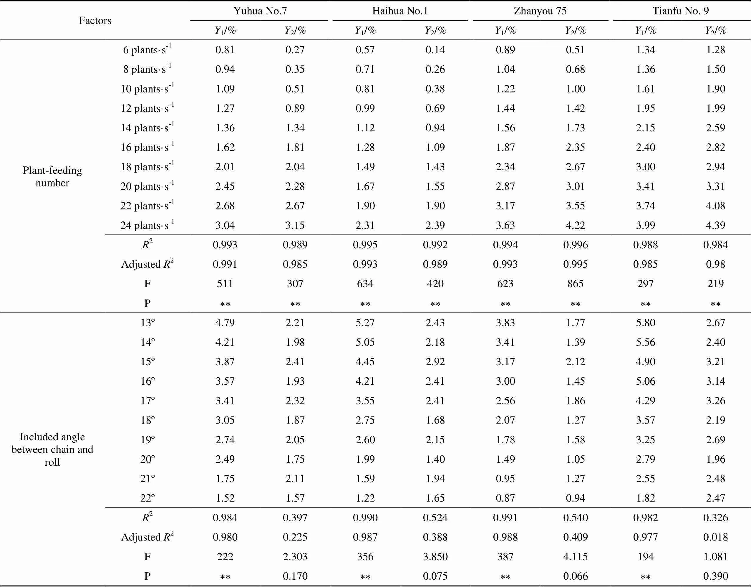
Table 2 Single factor test results
Note: When the single factor test about the plant-feeding number was carried out, the included angle was set as 15°; When the single factor test about the included angle was carried out, the plant-feeding number was set as 12 plants·s-1;1was unpicked rate, %;2was breakage rate, %.
As shown in Table 2, the pods unpicked rate gradually increased with the increase of the plant feeding number. The pods breakage rate increased with the increase of the plant-feeding number. The possible reasons were as follows: 1) when the processing period and the peanut pod-picking frequency were unchanged at the pod-picking segment, with the increase of the plant-feeding number, plants overstocked, and the number of pods required for being picked on the pod-picking blade of unit length increased in unit time. However, the clamping chain velocity was constant, that caused the inner pods remaining unpicked when the crowded plants passed through processing area, and then the pods unpicked rate increased. 2) The center distance of the double rolls kept constant, therefore the staggered space of the pod-picking blades remained unchanged. With the increase of the plant-feeding number, the volume per unit occupied by the plants decreased relatively that made plants cluster together tightly. Then the probability of damage of pods increased, which resulted in the increase of the pods breakage rate.
As shown in Table 2, the pods unpicked rate gradually increased with the decrease of the included angle. The possible reasons were as follows: with the decrease of the included angle, the pod picking effective range of the roller was reduced, and the peanut pods beyond the pod picking effective area could not been picked up at the pod picking stage, which resulted in the increase of the pods unpicked rate. Different peanut varieties has different plant layer thickness, pod number and pod range, therefore, under the same experimental conditions, the pods breakage rate and pods unpicked rate of different peanut varieties were different.
2.6 High-speed photography test
The research showed that the high speed photography technology could reveal the working mechanism of the main working parts of agricultural machinery[28-31]. In this paper, high speed photography technology was used to observe and analyze the process of peanut pod picking, the feeding and picking process, and the material status after picking.
Fig.10 showed the 4 images in the high speed video taken from the pod-picking blades and pods (the sequence is 1-4). The circle and rectangle in Fig.10 were used to mark the currently referenced pod and podding segment. After the pods entered the pod picking area, the pods, roots, and pod stalk mixed and overlapped together. The pod segment did not present a steady rectilinear motion, but was surging up from side to side. The pod layer became fluffy by the surging movement, when the outer pods was impacted by the pod-picking blade, the pod segment was instantly compressed, and the outer part of pods separated from the pod stalk. Meanwhile, soil, broken roots, broken branches and other debris were generated. After the first impact, pods were not immediately separated from the pod stalk. The pods slid across the outer edge of the pod-picking blade swing and turning because of inertia. Then the pods were impacted by the next pod-picking blade. The above process repeated constantly. After over two times, the pods separated from the pod stalk. As the outer pods were separated and fell, the thickness of the pod layer became thin, and the inner pod repeated the above process. During the pod-picking process, different positions and angles caused great differences in initial speed and direction of pods movement.
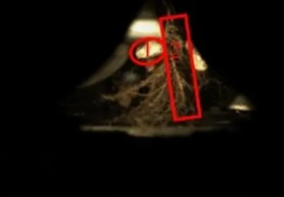
a. First image b. Second image
c. Third image d. Fourth image
Fig.10 High speed photography of pod-picking blade and pods
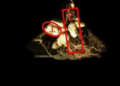
Fig.11 showed the 6 images in the high speed video of a pod-picking cycle (the sequence is 1-6). The first picture was the position of the plant before feeding. The plants were in vertical feeding status, and entered the picking entrance orderly. The second picture was the feeding position of the plants. When the plants entered the pod-picking area from the feeding entrance, the roots of the plants contacted with the 2 rollers first, then plants attitude changed. Under the impact of the roller, the broken root and soil were thrown along the tangent direction between the two rollers. The third picture was the first pod-picking operation after pods entering the rollers. For different peanut varieties, the initial position of pod picking occurred was different in the rollers. The moment when pods at the bottom of the plants contacted with the two rollers, the pods were impacted with the high speed rotation pod-picking blade and separated from the plants immediately. The pods separated would be accelerated downward along the roller in the approximate tangential direction. The fourth picture was the stable pod-picking stage after the plants entered the pod picking effective area. The pods entered the rollers in turn from bottom to top. The pods were separated from the pod stalk by the impact of the pod-picking blade, and mixed with broken branches, and broken soil, which were inter-impact during falling down, therefore the pods spattered out of the tangential direction of the two rollers. The fifth picture was the pod-picking completing stage of pods on the upper part of plants. All pods entered the rollers and completed the separation.
a. First image b. Second image c. Third image

d. Fourth image e. Fifth image f. Sixth image
Fig.11 High speed photography of one picking cycle
The sixth picture was the pod-picking completing stage. Under the effect of anti-winding device, the plants were disengaged from the pod-picking device smoothly. During a pod-picking cycle, picture 1 and 2 formed the plant feeding stage, picture 3 to 5 formed the pod-picking stage, picture 6 formed the stage in which the plants were separated from the roller. It could be seen that the working process corresponding to each stage was consistent with the theoretical design.
3 Conclusion and discussion
1) The semi-feeding test-bed for peanut pod picking was developed, which had the functions of key parameters adjustment and collection, process image acquisition and plant fresh keeping. The semi-feeding test-bed was mainly composed of a frame, an automatic feeding platform, a clamping- carrying device, a peanut pod-picking device, a control system, sensors, a converter motor and a high-speed photography system. This paper focuses on the design and analysis of the automatic feeding platform, the clamping- carrying device and the control system.
2) The key technical indexes of the semi-feeding test-bed are as follows: the pod-picking roller length was 500, 800, 1 000 mm; the double rollers center distance was 170-220 mm; the rollers diameter was 160, 200, 240 mm; the distance between the centers of the front end of the roller and the clamping chain was 200-300 mm; the distance between the centers of the back end of the roller and the clamping chain was 100-150 mm; the roller rotation rate was 200-1 000 r/min; the clamping chain velocity was 0.5-2.5 m/s; the high speed camera version: FastecHispe 5.
3) On the test-bed, single factor test of the plant-feeding number and the included angle and power consumption showed that the plant-feeding number had a great effect on the pods breakage rate and unpicked rate. The included angle had a great effect on the pods unpicked rate, but a little effect on the pods breakage rate; High-speed photography experiments revealed the process of pod-picking blade on the peanut pod series, pod vine separation and internal mechanism; The semi-feeding test-bed for peanut pod picking could provide effective technical means for further studies on the mechanism of the pod-picking working.
The influence factors of the breakage rate and unpicked rate of semi-feeding device for peanut pod picking are as follows: The plant-feeding number, the included angle, the clamping and transporting velocity, the linear velocity of the peanut pod picking blade, the roller length, the automatic feeding platform velocity, the center distance of the double rolls and so on. Therefore, single factor tests, not covered in the previous study, on the effect of the plant-feeding number and the included angle, and on the working index upon the semi-feeding test-bed, could provide the basis for the multiple parameter optimization experiment with the aim of controlling the breakage rate and unpicked rate.
In addition to working and structure parameters, the breakage rate and unpicked rate of semi-feeding device for peanut pod picking are also related to the connection strength between peanut steam and stalk, the connection strength between peanut pod and stalk, and the compressive force of pods. However, the three factors mentioned above are also determined by the other complex factors such as variety and maturity. In order to reveal the change mechanisms of the breakage rate and unpicked rate, the systematic studies about the above peanut biomechanical characteristics will be carried out by the high-speed photography test in the future.
[1] Wang Xiaoyan, Liang Jie, Shang Shuqi, et al. Design and experiment of half feeding type peanut picker[J]. Transactions of the Chinese Society of Agricultural Engineering (Transactions of the CSAE), 2008(9): 94-98.
[2] Wang Bokai, Hu Zhichao, Wu nu, et al. Design and experiments of 4HZB-2A peanut picker[J]. Chinese Agricultural Mechanization, 2012(1): 111-114.
[3] Lv Xiaolian, Wang Haiou, Zhang Huijuan, et al. Present situation and analysis of peanut picking technology and equipment[J]. Hubei Agricultural Sciences, 2012, 51(18): 4116-4117.
[4] Wang Xiaoyan. Device and Experiment Research on Half Feeding Type Peanut Stripping Tester[D]. Qingdao: Qingdao Agricultural University, 2006.
[5] Hu Zhichao. Study on Key Technologies of Half-Feed Peanut Combine Harvester[D]. Nanjing: Nanjing Agricultural University, 2011.
[6] Hu Zhichao, Wang Haiou, Peng Baoliang, et al. Optimized design and experiment on semi-feeding peanut picking device[J]. Transactions of the Chinese Society for Agricultural Machinery, 2012, 43(Supp.1): 131-136.
[7] Yang Ranbing. Study on Design Principle and Tests for Main Parts of 4HQL-2 Peanut Combine[D]. Shenyang: Shenyang Agricultural University, 2009.
[8] Hu Zhichao, Peng Baoliang, Yin Wenqing, et al. Design of 4LH2 type half-feed and self-propelled peanut combine[J]. Transactions of the Chinese Society of Agricultural Engineering (Transactions of the CSAE), 2008, 24(3): 148-153.
[9] Reaves Johnson. Green peanut harvester: 4687064[P]. 1986-03-24.
[10] Kuo-Ming Wang. Peanuts harvester and its harvesting method: 4607703[P]. 1985-09-09.
[11] Wang Dongwei, Shang Shuqi, Han Kun. Design and test of 4HJL-2 harvester for peanut picking-up and fruit-picking[J]. Transactions of the Chinese Society of Agricultural Engineering (Transactions of the CSAE), 2013, 29(11): 27-36.
[12] Shang Shuqi, Li Guoying, Yang Ranbing, et al. Development of 4HQL-2 type whole-feed peanut combine[J]. Transactions of the Chinese Society of Agricultural Engineering (Transactions of the CSAE), 2009, 25(6): 125-130.
[13] Wang Dongwei, Shang Shuqi, Zhao Dajun, et al. Type-4HBL-4 two-ridges and four-lines semi-feeding self-propelled peanut combine harvester[J]. Transactions of the Chinese Society for Agricultural Machinery, 2013, 44(10): 86-92.
[14] Hu Zhichao, Peng Baoliang, Zhang Yanhua, et al. Two ridges peanut combine harvester: ZL201310280913.9[P]. 2015-08-05.
[15] Wang Dongwei. Study on Key Mechanism of Peanut Combine Harvester[D]. Shenyang: Shenyang Agricultural University, 2013.
[16] Su Zhan. Study on Semi-Feeding Peanut Picker with Double-Roller Breeding Testing Device[D]. Shenyang: Shenyang Agricultural University, 2016.
[17] Gao Lianxing, Su Zhan, Chen Zhongyu, et al. Design and experiment of double-roller semi-feeding peanut picking device for breeding in mini type area[J]. Transactions of the Chinese Society for Agricultural Machinery, 2016, 47(9): 93-98.
[18] Lü Xiaorong, Lü Xiaolian, Wang Tingyu, et al. Virtual simulation and experimental research of half-feed peanut picker[J]. Journal of Northwest A&F University, 2017, 45(1): 190-196.
[19] Hu Zhichao, Peng Baoliang, Xie Huanxiong, et al. Semi-feeding peanut pod-picking device: ZL200910212625.3[P]. 2011-10-05.
[20] Wang Bokai. Design and Research on Half Feeding Type Peanut Picker[D]. Nantong: Nantong University, 2012.
[21] Hu Zhichao. Study on Key Technologies of Half-Feed Peanut Combine Harvester[M]. Beijing: China Agricultural Science and Technology Press, 2013.
[22] Hu Zhichao, Wang Haiou, Wang Jiannan, et al. Experiment on 4HLB-2 type half feed peanut combine harvester[J]. Transactions of the Chinese Society for Agricultural Machinery, 2010, 41(4): 79-84.
[23] Ralph Hughes. John Deere Peanut Combines[J]. Machinery Feature, 1997(2): 1-6.
[24] Padmanathan P K, Kathirvel K, Duraisamy V M, et al. Influence of crop, machine and operational parameters on picking and conveying efficiency of an experimental groundnut combine[J]. Journal of Applied Sciences Research, 2007(8): 700-705.
[25] Padmanathan P K, Kathirvel K, Manian R, et al. Design development and evaluation of tractor operated groundnut combine[J]. Journal of Applied Sciences Research, 2006(12): 1338-1441.
[26] Butts C L, Sorensen R B, Nuti R C, et al. Performance of equipment for in-field shelling of peanut for biodiesel production[J]. Transactions of the ASABE, 2009, 52(5): 1461-1469.
[27] Butts C L, Sorensen R B, Nuti R C, et al. Performance of equipment for in-field peanut shelling[J]. ASABE Annual International Conf, 2009(7): 1-18.
[28] Wang Jing, Liao Qingxi, Tian Boping, et al. The present and development tendency of high-speed photography applied on agricultural machinery[J]. Journal of Agricultural Mechanization Research, 2007(1): 184-186.
[29] Yi Shujuan, Wang Chun, Mao Xin, et al. Observation and analysis of motion rule of free kernel in threshing and separating space[J]. Transactions of the Chinese Society of Agricultural Engineering (Transactions of the CSAE), 2008, 24(5): 136-139.
[30] Yi Shujuan, Jiang Enchen. High-speed photography analysis on process of threshing of axial flow threshing and separating installation[J]. Transactions of the Chinese Society for Agricultural Machinery, 2008, 39(5): 52-55.
[31] Zong Wangyuan, Liao Qingxi, Huang Peng, et al. Design of combined rape threshing device and analysis of rape cane movement trail[J]. Transactions of the Chinese Society for Agricultural Machinery, 2013, 44(Supp.2): 41-46.
半喂入式花生摘果试验台设计与试验
胡志超,王 冰,于昭洋,彭宝良,张延化,檀律科
(农业部南京农业机械化研究所,南京 210014)
为深入开展半喂入式花生摘果装置作业机理、结构参数和作业参数优化等研究,设计了自动喂秧平台、控制系统、参数调节系统和保鲜库,选配高速摄像系统,并与已有试验台进行技术集成,研制成半喂入式花生摘果试验台。该试验台具备关键参数调节和采集、作业过程图像获取和植株保鲜等功能,主要包括机架、自动喂秧平台、夹持输送装置、摘果装置、控制系统、传感器、变频电机和高速摄影系统等。试验台的主要技术指标为:摘果辊长度500,800,1 000 mm,摘果辊直径160,200,240 mm,摘果辊后端中心与夹持输送链的距离100~150 mm,摘果辊的转速200~1 000 r/min,夹持输送链的速度0.5~2.5 m/s。在试验台上,对前期尚未涉及的供给株数、链辊夹角等因素、摘果辊功耗等进行了试验研究,开展了摘果过程高速摄影试验研究。结果表明:供给株数对未摘净率和破碎率影响较大;链辊夹角对未摘净损失影响较大,对破碎率影响较小;摘果功耗随着供给株数的增大呈递增规律;高速摄像系统能够揭示摘果叶片与花生果系的作用过程、果秧分离行为和内在机理。该半喂入式花生摘果试验台可为进一步深入开展摘果作业机理研究提供参考。
农作物;设计;优化;花生;半喂入;摘果;功耗;高速摄影
10.11975/j.issn.1002-6819.2017.17.006
S225.7+3
A
1002-6819(2017)-17-0042-09
2017-08-04
2017-08-17
National Natural Science Foundation of China (Grant No. 51375247); China Agriculture Research System for Peanut (Grant No. CARS-14-Mechanized Equipment); Agricultural Science and Technology Innovation Program of the Chinese Academy of Agricultural Sciences (ASTIP, CAAS).
Hu Zhichao, Professor, the major research direction is harvest and processing technology of crops. Email: zchu369@163.com.
猜你喜欢
现代仪器与医疗(2022年3期)2022-08-12
农业科技与信息(2022年9期)2022-06-18
中国麻业科学(2021年6期)2022-01-21
装备制造技术(2020年11期)2021-01-26
临床检验杂志(电子版)(2020年1期)2020-04-03
河北科技师范学院学报(2020年1期)2020-01-19
制造技术与机床(2019年6期)2019-06-25
制造技术与机床(2018年12期)2018-12-23
学苑创造·B版(2015年12期)2016-06-23
小天使·二年级语数英综合(2015年5期)2015-05-15
- 农业工程学报的其它文章
- 无线遥控步行插秧机的设计与试验
- 网链式花生地残膜回收机设计与试验
- 差速水稻钵苗Z字形宽窄行移栽机构设计
- Design and evaluation of PID electronic control system for seed meters for maize precision planting
- 玉米花生间作播种施肥一体机研制与试验
- Relationship between frequency spectrum characteristics and vibration responses of Ginkgo biloba trees during mechanical harvesting operation