
基于第二代高温超导带材的高载流超导导体研究进展
2017-11-24 06:12王银顺
电工电能新技术 2017年11期
王银顺
(1. 新能源电力系统国家重点实验室, 华北电力大学, 北京 102206; 2. 高压与电磁兼容北京市重点实验室, 华北电力大学, 北京 102206)
基于第二代高温超导带材的高载流超导导体研究进展
王银顺1,2
(1. 新能源电力系统国家重点实验室, 华北电力大学, 北京 102206; 2. 高压与电磁兼容北京市重点实验室, 华北电力大学, 北京 102206)
由于其高临界电流密度以及优越的机械性能和电磁特性,第二代高温超导带材(也叫涂层导体)在高温低场的电力传输和低温高场下的磁体应用具有广阔的应用前景。在电力传输的低场应用中,高温超导导体在低电压大容量场合需要几千安培甚至上万安培的传输电流。在大型高场磁体应用方面,为了避免由于过高电感在磁体失超和快速关断过程中的感应高压问题,大载流容量、高电流密度高温超导导体在运行于4.2K及以下温度的大型高场超导磁体方面具有很好的应用前景。近年来,基于第二代高温超导带材,国际上相继提出了几种高载流容量的高温超导导体,本文介绍几种高温超导导体的结构及研发现状和进展,并对其结构、性能和工艺进行简单的比较和评述。
第二代高温超导带材; 电缆; 涂层导体; 导体; 股线; 管内电缆导体; 卢瑟福电缆
1 引言
在过去二十几年中,实用高温超导材料的研究取得了很大进展。采用相对简单的粉末管装法(Powder-in-Tube, PIT) 以Bi2223为代表的第一代高温超导带材BSCCO实现了工业化生产[1]。但是,由于第一代高温超导带材使用贵金属Ag,且在高场下性能比第二代高温超导带材REBCO差,近年来国际上BSCCO带材的生产逐渐停止。以REBCO为代表的第二代高温超导带材(涂层导体)经过十几年的发展,制备工艺逐渐成熟。目前,第二代高温超导带材基板及织构化隔离层的制备工艺有离子束辅助沉积(Ion Beam-Assisted Deposition, IBAD)[2],轧制辅助双轴织构(Rolling-Assisted Biaxially Textured Substrate,RABiTS)[3]和倾斜基板沉积法 (Inclined Substrate Deposition,ISD)[4]。在基板上采用脉冲激光沉积法(Pulsed Laser Deposition, PLD)[5]、化学气相沉积法(Chemical Vapor Deposition, CVD)[6],化学溶液沉积法(Chemical Solution Deposition, CSD)[7], 金属有机沉积法(Metal Organic Deposition, MOD)[8], 金属有机化学气相沉积法(Metal Organic Chemical Vapor Deposition, MOCVD)[9],循环沉积反应共蒸发法(Reactive Co-Evaporation by Cyclic Deposition and Reaction, RCE-CDR)[10], 以及沉积反应共蒸发法(Reactive Co-Evaporation by Deposition and Reaction,RCE-DR)[11,12]。国内外许多公司具有生产单根百米量级超导带材长度的能力[13-16]。 尤其是日本古河电气公司的子公司Superpower公司通过在ReBCO薄膜中掺杂Gd和Zr技术,超导带材的临界电流各向异性得到极大改善,同时其机械特性和高场载流能力得到显著提高[17]。此外,韩国SuNAM公司采用改进的RCE-DR工艺,超导带材的载流能力取得了很大提高,液氮自场下临界电流达到794 A/cm,在650m长度上获得极高的临界电流均匀性,其生产速度达到120m/h[18]。值得一提的是,与其他高温超导体相比较,第二代高温超导带材的机械性能中沿c轴方向的临界拉应力较差。
尽管如此,单根超导带材载流有限,多根并联使用不可避免。常用低温NbTi超导线制作电缆导体,容易实现扭绞和换位,目前商业化高温超导带材厚度在0.1mm左右,宽度在2~12mm范围,常规制作多根并联超导电缆导体过程中的扭绞和换位非常困难。为了解决这些技术难题,近几年国际上提出了几种基于第二代高温超导带材的超导导体结构,每种电缆导体在交流损耗、加工工艺、工程电流密度等方面各有利弊。本文介绍几种基于第二代高温超导带材的高载流电缆导体研发进展情况,简要分析比较各种超导电缆导体的技术特点,为高载流高温超导导体在高温低场和低温高场的应用提供有益参考。
2 RAAC导体/电缆
德国是进行基于第二代高温超导带材进行超导导体/电缆研发的最早国家,为了均流和减小交流损耗[19-21],2006年德国卡尔斯鲁厄研究中心(Forschungszentrum Karlsruhe, FZK) 的 Goldacker W教授提出了由第二代高温超导带材组成的完全换位导体的方法[22,23],通常简称RACC(Roebel Assembled Coated Conductor)。将一定宽度的第二代高温超导带材沿着长度方向周期性地裁剪成“梯形”,可以采用气动冲切或激光切割方法进行裁剪。然后进行编织形成Roebel电缆导体[24,25]。
RACC导体/电缆最显著的特点在于其与众不同的结构,这种结构载流均匀、可以减小交流损耗,使得RACC导体/电缆具有低交流损耗和高载流能力的特点[19]。研究发现宽度较小的高温超导导体和位置交换的超导结构可以减少交流损耗,因为磁场的磁力线可以进入超导带材的内部间隙,但是在生产上细丝状的高温超导导体并不能实现,并且简单的切割不利于实际生产[20-22]。RACC超导/电缆结构由特定形状的涂层导体相互换位组装而成[23],其导体/电缆图片如图1所示,常用涂层导体经过手工裁剪的“梯形”涂层导体实物如图1(a)所示,手工编织加工完成后的RACC导体/电缆试样如图1(b)所示。通过气动冲压切割和机械编织的RACC导体/电缆实物照片如图2所示。

图1 用涂层导体手工编织的RACC导体/电缆Fig.1 RACC / cable manually woven by using CC

图2 机械编制的RACC导体/电缆试样Fig.2 RACC/cable woven by machine
为了尽量减小带材宽度,RACC导体/电缆中带材之间的换位是利用正反梯形相互交替的方法来实现的,并有利于多根的换位组装,可以构成有更高电流容量的RACC导体/电缆[24,25]。RACC导体/电缆加工工艺日渐成熟,Goldacker W, Frank A等人采用45根更薄的涂层导体进行RACC的制作[26]。FZK手工制作的 6m长 RACC导体/电缆如图3所示,该导体/电缆由17根超导带材组成,带材宽度为5.5mm,换位长度为226mm, 77K自场下临界电流为2.05kA[27]。

图3 RACC 导体/电缆实物Fig.3 Overview of RACC/cable
研究发现RACC导体/电缆具有临界电流密度高、在交变磁场和交流载流下均流的特点,而且在垂直场下的交流损耗也显著降低[24]。目前,FZK通过手工只能制作5m长RACC导体/电缆。为了避免超导带材过度弯曲和塑形形变,RAAC导体的机械绕制非常复杂。通过与新西兰工业研究有限公司(Industrial Research Ltd,IRL) 合作, 2009年首次实现了由5mm宽的15根超导带材绕制的7.5m长RACC导体/电缆[28-30]。对常规电缆生产线进行部分改造,即可进行RACC导体/电缆的加工。在稍加改造的常规电缆生产线上加工RACC导体/电缆的加工现场如图4所示,可以实现实用长度RACC导体/电缆的生产和加工。
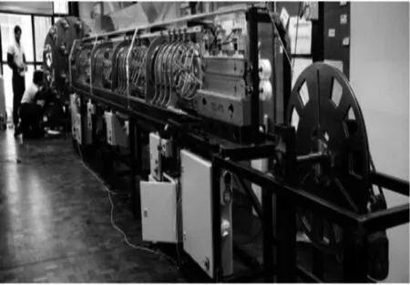
图4 IRL电缆公司RACC加工生产线[29]Fig.4 Production line o IRL-General Cable for assembling RACC
新西兰惠灵顿维多利亚大学等单位采用激光切割技术切割超导带材[30],实现了商业化RACC导体/电缆生产,为欧洲委员会支持的EuCARD-2未来磁体计划提供的34m 长的RACC导体/电缆实物[31-34]如图5所示。

图5 新西兰惠灵顿大学提供的34m长的RACC导体/电缆Fig.5 RACC /cable Cable supplied by Victoria University of Wellington, New Zealand
用10kA级RACC导体/电缆首次绕制完成了Feather-M0跑道型线圈,并进行了实验,由RACC导体/电缆绕制的Feather-M2跑道型线圈三维效果图如图6所示,该线圈在Feather-M0实验完成后,进行实际尺寸的Feather-M2跑道型线圈的绕制。

图6 全尺寸RACC导体/电缆绕制的三维模型线圈Fig.6 Rendered image of the full three-dimensional Feather-M2 coil model by RACC/cable
考虑到大型空中飞行器电力系统电压低(<1.0kV)、功率和重量不断提高的情况,2016年俄罗斯科学研发电缆研究所(the Russian Scientific Research and Development Cable Institute, SRDCI) 探讨RACC导体/电缆在飞行器电力系统中的应用可行性[28]。此外,RACC导体/电缆在大型军用舰船、互联网数据中心等低压高电流、大容量输电场合也具有潜在应用前景。
RAAC导体/电缆的优点是实现了完全换位,电流均匀分布;缺点是垂直带面磁场高,对临界电流影响大。临界电流衰减大,浪费带材、成本高、力学性能差、不紧凑,需要环氧浸泽固化。根据SRDCI研究,RACC导体/电缆的损耗高于单相冷绝缘电缆和三轴电缆,由于磁场临界电流衰减和由于切割带材临界电流衰减比单相冷绝缘电缆和三轴电缆分别高1倍和10倍,超导带材用量也比单相冷绝缘电缆和三轴电缆分别多2倍和1倍[28],因此作为输电系统,RACC导体/电缆的应用值得商榷。在高场磁体应用方面应更具有优势。
3 CORC导体/电缆
CORC(Conductor On Round Core)导体/电缆是由美国国家标准技术研究所(National Institute of Standard Technology, NIST)与Colorado大学合作,提出的一种结构紧凑柔性超导导体,这种导体具有低电感、低交流损耗和高临界电流的特点[35-37],拟用于电力直流输电、空军及海军电力传输和低温高场应用。CORC导体/电缆由3部分构成,中心骨架使用的是截面较小的铜棒或铜绞线,中间部分是将高温超导带材螺旋缠绕在中心骨架上,最外侧部分使用绝缘材料进行包覆,与超导电缆导体类似。并研制出1m长、外径6.5mm导体,进行了液氮温度实验和弯曲接卸性能试验。在76K温度自场情况下,其临界电流达到2796A,弯曲半径为125mm。其试样结构截面图如图7所示,骨架为直径5.5mm的铜绞线,绕制8层超导带材,CORC导体/电缆主视图如图7(a)所示;5倍放大截面图如图7(b)所示,中心为铜绞线;实物截面图如图7(c)所示,导体外径为6.5mm。黑色区域为绕制在骨架上的碳纸。现场加工照片如图8所示,可以精确控制绕制张力、角度和超导之间的间隙,实现了实用长度的加工工艺,加工的12m长CORC导体/电缆长样如图9所示,骨架直径为5mm,由38根4mm宽、0.1mm厚的古河电气子公司-SuperPower公司生产的超导带材绕制而成。
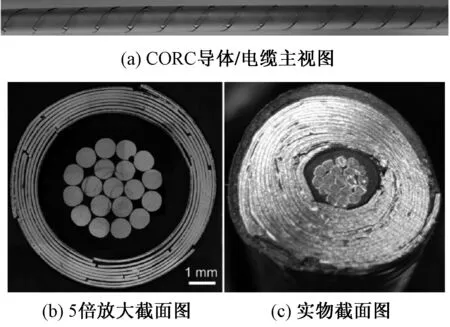
图7 紧凑型高温超导导体/电缆示意图Fig.7 View of compact CORC/cable
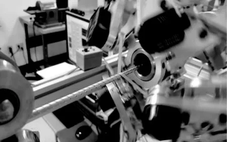
图8 CORC导体/电缆加工现场照片Fig.8 Photo of processing CORC/cable
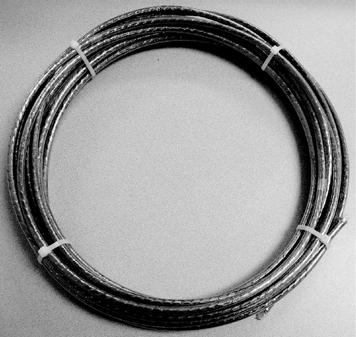
图9 12m CORC导体/电缆样品Fig.9 CORC/cable specimen with 12m in length
CORC导体/电缆中心骨架直径比超导电缆小很多,所以CORC导体/电缆具有较高的临界电流密度。CORC导体/电缆的临界电流密度也会随着缠绕层数的增加而随之增加。CORC导体/电缆的带材缠绕的方式为螺旋缠绕,所以其磁场平行于带材表面,因此超导带材的临界电流的衰减要比磁场垂直带材的导体小的多。研究人员制作了不同层数的CORC导体/电缆,最大的临界电流为6.8kA,其工程电流密度达到86.58A/mm2[38]。
在2013年,van der Laan D C利用CORC导体/电缆制作了适用于高场20T的高场磁体,该磁体结构在4.2K、19T的测量条件下临界电流为5.021kA, 并且电流密度非常高,达到了114A/mm2[39]。
4 TSTC 导体/电缆
TSTC(Twisted Stacked-Tapes Cable)导体/电缆是由麻省理工学院(MIT)Takayasu T等人提出的一种新型超导导体,由超导带材直接堆叠在一起,形成矩形截面超导导体,然后扭绞形成平行排列的高温超导导体[40-42],其试样如图10所示。

图10 TSTC导体/电缆样品Fig.10 TSTC/cable specimen
TSTC导体有着极高的临界电流密度和良好的弯曲特性,由32根4.0mm宽,0.098mm厚的高温超导带材堆叠以200mm扭矩扭绞的TSTC导体/电缆结构股线,端部以Bi2223银包套带材与REBCO带材交替堆叠焊接处理,液氮温度下,接触电阻小于10nΩ。临界电流达到1.5kA,在液氦温度下可达10kA。由于TSTC导体/电缆将超导带材平行堆叠,带材能够相互支撑,可以防止带材受到的应力过于集中,并且多根带材扭绞可以减轻带材侧向弯曲程度,在弯曲半径为140mm时,由24根带材组成的TSTC导体/电缆临界电流退化仅为6%,因此TSTC导体/电缆可用于制作超导线圈[43-45]。
为了对超导带材进行保护,将超导堆叠导体嵌入有螺旋沟槽的金属芯导体,外加金属护套的方式构成一种灵活的超导导体,该导体有良好的机械特性,可应用于大型超导磁体线圈[46-49]。单螺旋沟槽单股和三螺旋沟槽三股TSTC导体/电缆试样图片如图11所示。为了实现更大电流的超导导体,可由单股TSTC导体/电缆并联并扭转可制成更高载流导体。

图11 带护套TSTC导体/电缆试样Fig.11 TSTC /cable specimen with metal sheath
5 简单堆叠导体(SSC)
100kA 级简单堆叠导体(Simply-stacked HTS Conductors, SSC)是由日本国立核聚变研究所(the National Institute for Fusion Science, NIFS)提出的一种简单堆叠超导导体。为了建造螺旋形核聚变演示反应堆,超导线圈导体要在高达13T的磁场下载流能力达到100kA,研究人员采用在铜和不锈钢套中把超导带材并排堆叠的方法来构造大电流导体,其结构如图12所示。图12中为2排6层的结构,实际结构为3排18层,一共有54根超导带材构成(带材宽度10mm,厚度0.22mm),77K下临界电流约600A[50]。

图12 100kA级高温超导简单堆叠导体结构Fig.12 Structure of 100-kA class HTS SSC
通过实验表明,该导体具有很高的载流能力,在4.2K温度和0.45T磁场下的临界电流达到118kA,在20K温度和5.3T外场下临界电流达到100kA[50]。
6 扭绞圆股线(RS)
2013年,Uglietti D等人提出一种高载流容量超导圆截面结构导体,其结构中心部分类似TSTC导体的布局结构,采用平行的REBCO带材堆叠扭绞而成,然后使用2根挤有方形沟槽的半圆形截面铜棒将其夹紧,堆叠带材和铜棒进行镀锡焊接后扭绞制作成圆截面股线(Round Strand, RS)[51-53]。结构示意和实物图片如图13所示。

图13 圆截面股线结构图和实物图片Fig.13 Sketch of the round strand
在77K液氮温度下每根股线的临界电流大约为1.15kA。圆截面扭绞股线焊接主要有2种结构:“S”型和“Plus”型,有两种加工工艺:先扭绞后焊接(first-twisted-then-soldered, TS),先焊接后扭绞(first-soldered-then-twisted, ST),如图14所示[54-56]。

图14 金属包套焊接结构示意和实物Fig.14 Schematic view and photo of soldering profile
机械性能实验表明,“Plus”型加工导体的机械性能优于“S”型工艺性能。退火处理可以大大提高弯曲性能,未退火的试样弯曲半径约为500mm。在经过300℃温度预退火处理1h后,弯曲半径可以减小到240mm,弯曲半径减小一半[54]。
7 HTS-CroCo导体/电缆
HTS-CroCo(HTS-Cross Conductor)导体/电缆是由FZK的Fietz W H等人新近提出的一种新型超导导体,这种结构的导体适用于长距离导体的制作,可以优化工程电流密度并简化导体之间的连接[57,58]。与TSTC导体/电缆和扭绞圆截面股线超导导体类似,由宽度为4mm的超导带材对称地堆叠在6mm导体两侧,然后以圆截面铜包套包裹堆叠导体,铜包套与导体之间的间隙以锡填充,中间超导导体可以扭绞。该HTS-CroCo导体/电缆试样、截面示意图和其2种截面结构的实物照片如图15所示。为研究扭绞堆叠超导带材加金属护套挤压(即旋锻)的影响,采用机械方法对缠绕焊锡丝的试样进行不同外径下的挤压、旋锻处理实验, HTS-CroCo导体/电缆试样截面图如图16所示,HTS-CroCo导体/电缆超导芯缠绕Pb37Sn63焊锡丝并加外铜护套如图16(a)所示;挤压到直径为8.9mm时截面如图16(b)所示;挤压到直径为8.5mm时截面如图16(c)所示。铜管外套内外径分别为8.5mm和9.5mm。外径挤压到8.9mm时超导带开始变形,当挤压外径减小到8.5mm时,超导带材严重变形。经过试验验证,挤压直径9mm是安全的。

图15 HTS-CroCo导体/电缆结构示意图和试样及其截面图片Fig.15 Schematic view and specimen photo and cross sections of two types of HTS-CroCo/cable specimen

图16 旋锻对HTS-CroCo导体/电缆的影响Fig.16 Influence of jacketing with compaction by rotary swaging on HTS-CroCo cable
对于圆形截面的股线,很难以1种连续的方式进行扭转。采用HTS-CroCo导体/电缆结构,则可以依据形状配合的方式连续的扭转超导线芯,制作超导线芯的速度可以达到3m/min, 适宜长距离导体的制作。此外,通过结构优化,这种结构的导体工程电流密度可达700A/mm2,近期目标是在2017年该导体在77K温度自场条件下工程电流密度大于650A/mm2[59]。目前,HTS-CroCo导体/电缆短样机械加工1.1m实验完成,加工工艺基本成熟,可以进行实用长度的加工。
对于HTS-CroCo导体/电缆之间的连接、端部连接等技术进行了系统实验研究[60],同时对不同骨架材料的沟槽加工等技术进行理论和实验研究[61],为HTS-CroCo导体/电缆和由其制成的CICC导体和Rutherford电缆实用化储备关键技术。
8 准各向同性导体(QI-S)
由上文可知,国际上基于涂层导体提出的主要6种超导导体,外磁场下其任一截面上临界电流仍然具有各向异性的缺点。华北电力大学提出了临界电流准各向同性的高温超导导体概念[62,63]。其概念结构设计如图17所示,分别为圆截面和方形截面高温超导导体。导体由4股直接堆叠子股对称排列而成,外面以金属护套包裹。金属包套可以是铜、铝或不锈钢。3种不同金属包套的圆形和方形截面的导体短样图片如图18所示,超导线采用由古河电气子公司SuperPower公司生产的涂层导体。股线由4股堆叠股线对称组合排列,2股横向排列,2股纵向排列,每股子股线由18根2mm×0.1mm堆叠组成,单根带材在77K温度和自场条件下临界电流为48A。

图17 圆形和方形截面临界电流准各向同性股线示意图Fig.17 Schematic view of quasi-isotropic critical current strand specimen with circular and square cross sections

图18 准各向同性股线短样照片Fig.18 Photos of quasi-isotropic stand specimen
对3种包套材料的导体结构和加工工艺分别进行了系统研究,制作不同包套材料的股线试样。在液氮温度下进行了理论分析和实验。依据不同电流下股线自场和超导带材临界电流随磁场的变化特性,理论计算在77K温度和自场临界电流2.38kA,实验临界电流值为2.28kA, 两者接近。同时,在77K温度下,理论分析和实验测量了在外磁场0.1T和0.5T下股线临界电流的各向异性,归一化临界电流随外磁场角度的变化如图19所示。实验表明在0.5T以下,超导股线临界电流各向异性小于5%,验证了该股线临界电流的准各向同性[64-66]。

图19 归一化临界电流随外磁场角度的变化Fig.19 Plot of normalized critical current against angle of external magnetic field
此外,对该股线也分别进行了稳定性、机械特性、交流损耗等理论研究和实验研究[67-72],为股线的实际应用奠定了初步基础。
为实现实用长度股线的机械加工工艺,依据现有电力光缆生产线生产工艺,对圆截面超导股线生产工艺进行概念设计,其生产示意如图20所示。采用成熟的激光焊接技术焊接金属包套,使用不同结构磨具可以实现方形和圆形截面金属包套的焊接。
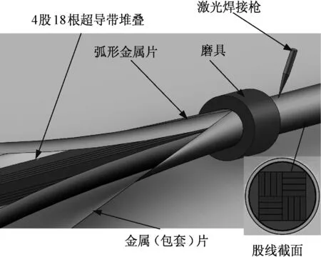
图20 圆截面实用长度股线加工成产示意Fig.20 Schematic of fabricating methods for Q-IS with round cross section
在现有光缆生产线上,采用成熟的激光焊接光纤技术进行的临界电流准各向的高温超导股线的加工。在中天集团科技股份有限公司光缆生产线上,加工现场如图21所示,完成了10m长度超导股线的加工,加工完成的导体如图22所示。通过10m长度股线的成功加工,可以实现长度的高温超导股线的加工[62,67]。

图21 临界电流准各向同性超导股线加工现场图片Fig.21 Overview of field fabrication equipment for quasi-isotropic starnd

图22 加工完成的10m长度临界电流准各向同性股线Fig.22 Quasi-isotropic stand in 10m length fabricated by production line
9 CICC导体
以上7种超导导体,除了应用于高温低场超导电力应用外,另一重要领域是低温高场下的大型超导磁体应用,将导体制作成管内电缆导体(Cable-In-Conduit Conductor, CICC)。
9.1TSTC导体/电缆-CICC导体
基于TSTC导体/电缆,设计成CICC导体,如图23所示,将铜或铝棒挤压加工成螺旋形多沟槽骨架,沟槽中放置堆叠超导线,骨架中心有孔,用以低温介质流过,超导带外放置铜线作为衬垫,外面铠装不锈钢, 通过测试相关机械及电磁参数取得了优化结构的电缆及更高的载流能力[73-75]。经过近3年的研发,CICC导体能够进行实用长度生产。由TRATOS Cavi S.p.A公司连续加工的150m长度的CICC导体结构如图24所示。中心为铝制骨架,沟槽通过460℃热挤压成形。

图23 基于TSTC导体/电缆的CICC导体结构Fig.23 CICC conceptual design of CICC based on TSTC cable

图24 TRATOS Cavi S.p.A 连续加工150m长CICC导体Fig.24 Image of spool collecting 150m aluminum slotted core manufactured by using continuous facility at TRATOS Cavi S.p.A
美国MIT基于TSTC导体/电缆提出另一种结构CICC导体结构概念,是9.1节CICC的进一步推广。相当于将9.1节中的CICC导体作为子缆,进一步组合成大电流容量的CICC导体,其典型截面结构概念设计之一[49,76-80]如图25所示。该CICC导体由6股子股线扭绞构成,每个子股线由3组TSTC导体/电缆扭绞构成,形成3×6结构CICC导体,中心为冷却通道。目前,此种CICC导体仍处于短样设计、实验研发阶段,未实现实用长度生产工艺。

图25 3×6 CICC导体结构设计Fig.25 Design of 3×6 CICC
9.2CORC导体/电缆-CICC导体
尽管CORC导体/电缆工程电流密度低于其他导体,但是其机械性能好,对于高场应用的CICC导体具有很好的应用前景。其CICC结构如图26所示,以铝铠装、中空管为冷却通道、由6根CORC导体/电缆扭绞组成[81-84]。1.7m CICC试样[85,86]如图26(b)所示,对于其端部连接技术基本完成,还未实现实用长度的成产。
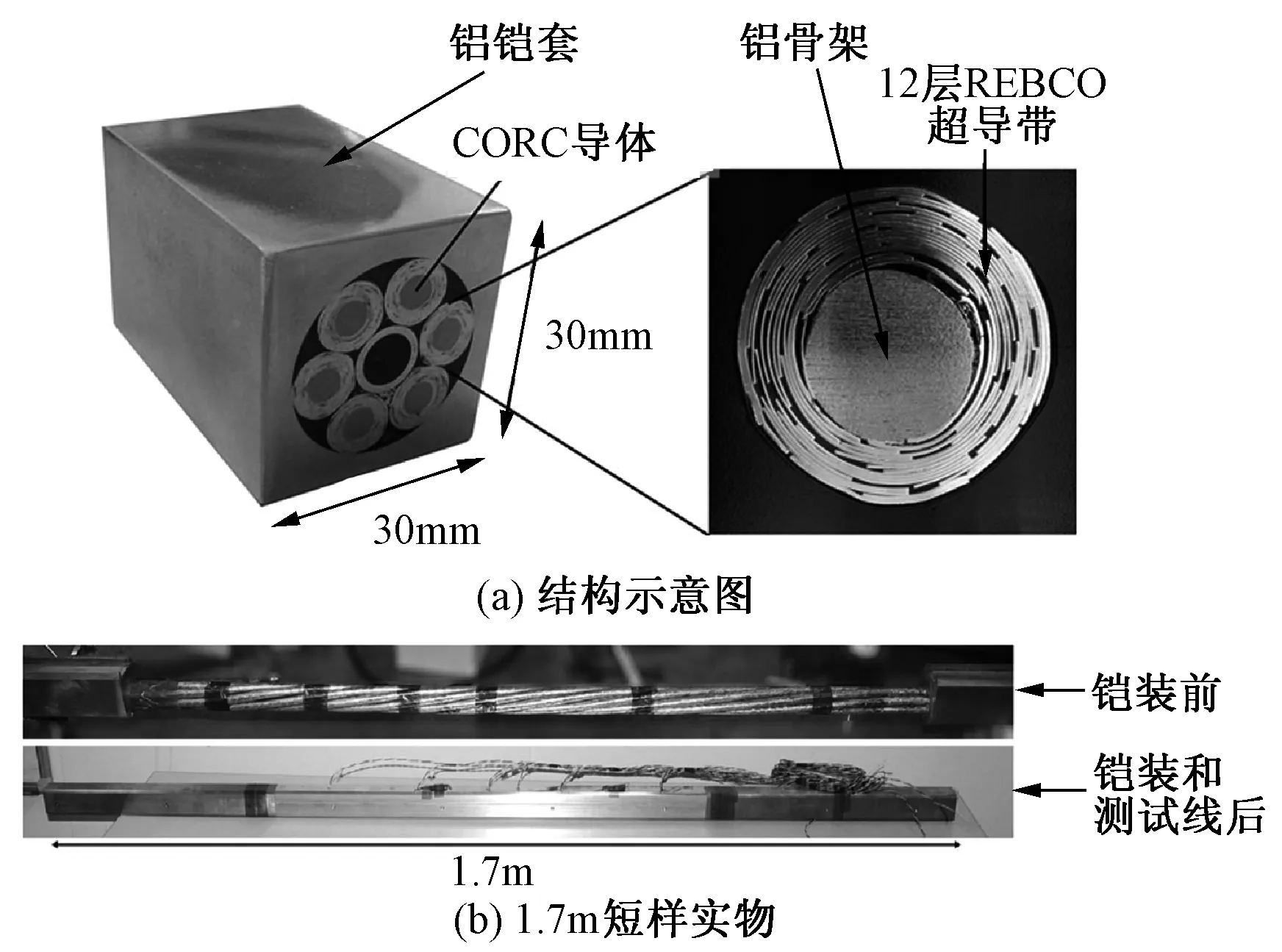
图26 基于CORC导体/电缆的CICC短样结构示意和试样.Fig.26 Schematic view and picture of CICC specimen based on CORC cables
此外,为了将 RACC导体/电缆应用于CICC导体,FZK已经开展了铝合金和无氧铜CICC骨架沟槽工艺研究[61],其骨架结构如图27所示,并开始研发基于RACC导体/电缆的CICC导体研究。

图27 Al6036合金和无氧铜骨架结构Fig.27 Example of possible formers as proposed by using Al6063 alloy and OFHC Cu
10 Rutherford电缆
高场大电流容量导体除了CICC外,为了降低交流损耗,另一种可换位大载流导体是Rutherford 电缆,由多根导体绕制在扁平状导体上,其结构示意如图28所示。原则上讲,上述7种超导导体/电缆都可以用来制作Rutherford电缆[59], 即所谓的涂层导体Rutherford电缆 (Coated Conductor Rutherford Cable, CCRC)。下面简单介绍目前已经开始进行研发的Rutherford 电缆的情况。

图28 Rutherford 电缆结构示意图Fig.28 Schematic view of Rutherford cable
10.1RACC导体/电缆-Rutherford电缆
2011年,FZK开始进行基于RACC导体/电缆的Rutherford 电缆的研究,由RACC导体/电缆绕制的Rutherford 电缆试样如图29所示,目标是研发10kA Rutherford电缆[87]。

图29 基于RACC导体/电缆导体的Rutherford 电缆试样Fig.29 Rutherford cable specimen made from RACC/cable
10.2HTSCroCo导体/电缆-Rutherford电缆
基于HTS Croco导体/电缆设计Rutherford电缆的概念也是由FZK提出,用HTS CroCo导体/电缆绕制在扁平铜或铝板上制成。HTS CroCo导体/电缆由厚度0.1mm和宽度4mm+6mm+4mm的第二代高温超导带材制成的,其截面示意如图30所示。
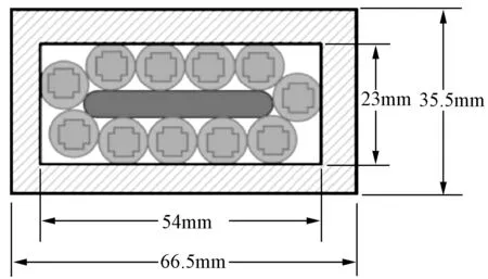
图30 11根HTS-CroCo导体/电缆铠装绕制的Rutherford电缆截面示意图Fig.30 Cross section of Rutherford cable with 11 HTS CroCo cables and jacked
10.3扭绞圆截面股线(RS)-Rutherford电缆
2015年,Uglietti D等人在单根扭绞圆截面股线的基础上,将20根单根股线沿铜板绕制Rutherford电缆结构,这种超导体结构的实物如图31所示,整个导体宽70mm厚19mm,长度2m, 在77K自场下,实验得到其临界电流1.15kA, 其n值达到25,估算在4.2K温度12T下,其工程电流密度达790A/mm2,大于同等条件下Nb3Sn的688A/mm[55,88-93]。

图31 Rutherford 电缆实物图Fig.31 Picture of prototype Rutherford cable
11 结论
国际上第二代高温超导带材工艺成熟,实现了商业化生产,但是由于单根带材载流有限,国内外提出了7种基于第二代高温超导带材的超导导体并进行相关关键技术工艺研究,为其高温低场电力应用和低温高场下的应用奠定了坚实基础。同时, 7种超导导体中的4种即RACC 导体/电缆、CORC导体/电缆、CroCo导体/电缆和圆截面股线(RS)已经研制成Rutherford 电缆短样;TSTC导体/电缆也已研制成实用长度CICC导体,为高场大电流应用做好技术了储备。
7种超导导体/电缆或股线的结构特征、临界电流各向异性特性以及工艺方法总结见表1,其中除了RACC导体/电缆必须使用第二代高温超导带材外,其他6种导体/电缆或股线不排除使用第一代高温超导带材。尽管有些方法和工艺对于实用长度导体的加工还不完全成熟,需要进一步研究,但是它们对于未来高场和大载流应用场合具有潜在的应用价值。

表1 7种超导导体/股线的结构和临界电流各向异性特性Tab.1 Geometrical structures and characteristics for seven types of superconducting conductors/strands
纵观国内外高温超导导体的研究进展,国外提出的6种超导导体已经进行了温度77K和4.2K下的研究和Rutherford电缆及CICC导体研究,而国内只有1种准各向同性股线(QI-S)研发,虽然实现了实用长度的生产工艺,但是只进行了液氮温度(77K)的实验研究,缺乏液氦温度(4.2K)下的研究和基于准各向同性股线的Rutherford电缆及CICC导体的实验研究。就目前看,这种差距趋势还在逐步扩大,希望引起国内相关管理部门和研究部门的关注。
[ 1] Larbalestier D, Gurevich A, Feldmann D M, et al. High-Tcsuperconducting materials for electric power applications [J]. Nature, 2001, 414(6861):368-377.
[ 2] Iijima Y, Tanabe N, Kohno O, et al. In-plane aligned YBa2Cu3O7-xthin films deposited on polycrystalline metallic substrates[J]. Applied Physics Letters, 1992, 60(6):769-771.
[ 3] Goyal A, Norton D P, Budai J D, et al. High critical current density superconducting tapes by epitaxial deposition of YBa2Cu3O7-xthick films on biaxially textured metals [J], Applied Physics Letters, 1996, 69(12):1795-1797.
[ 4] Balachandran U, Ma B, Li M, et al. Development of coated conductors by inclined substrate deposition [J]. Physica C Superconductivity & Its Applications, 2003, 392-396(1): 806-814.
[ 5] Watanabe T, Kuriki R, Iwai H, et al. High rate deposition by PLD of YBCO films for coated conductor [J]. IEEE Transaction on Applied Superconductivity, 2005, 15(2):2566-2569.
[ 6] Apetrii C, Schlorb H, Falter M, et al. YBCO thin films prepared by fluorine-free polymer-based chemical solution deposition [J]. IEEE Transaction on Applied Superconductivity, 2005, 15(2):2642-2644.
[ 7] Kashima N, Niwa T, Mori M, et al. Fabrication of coated conductors by multiple-stage CVD [J]. IEEE Transaction on Applied Superconductivity, 2005, 15(2):2763-2766.
[ 8] Goyal A, Li J, Martin P M, et al. Enhanced flux-pinning in Dy-doped MOD YBCO films on RABiTS[J]. IEEE Transaction on Applied Superconductivity, 2007, 17(2):3340-3342
[ 9] Vergnieres L, Donet S, Jimerez C, et al. MOCVD and spray pyrolysis for coated conductor synthesis [J]. IEEE Transaction on Applied Superconductivity, 2005, 15(2): 2759-2762.
[10] Oh S S, Ha H S,Kim H S, et al. Development of long-length SmBCO coated conductors using a batch-type reactive co-evaporation method [J]. Superconductor Science and Technology, 2008, 21(3): 034003.
[11] Matias V, Rowley E J, Coulter Y, et al. YBCO films grown by reactive co-evaporation on simplified IBAD-MgO coated conductor templates [J]. Superconductor Science and Technology, 2009, 23(1): 014018.
[12] Ko K P, Ha H S, Kim H K, et al. Fabrication of highly textured IBAD-MgO template by continuous reel-to-reel process and its characterization[J], Physica C Superconductivity & Its Applications, 2007, 463-465 564-567.
[13] V Selvamanickam, Chen Y, Xiong X, et al. High performance 2G tapes: from R&D to pilot-scale manufacturing [J]. IEEE Transaction on Applied Superconductivity, 2009, 19(3): 3225-3230.
[14] Oh S S, Kim H S, Ha H S, et al. Progress in research and development for REBCO coated conductors by reactive co-evaporation [J]. Progress in Superconductivity and Cryogenics, 2013, 15(4): 1-5.
[15] Lee J H, Mean B J, Kim T J, et al. Vision inspection methods for uniformity enhancement in long-length 2G HTS tape production [J]. IEEE Transaction on Applied Superconductivity, 2014, 24(5): 6900505.
[16] Selvamanickam V, Chen Y,Kesgin I,et al. Progress in performance improvement and new research areas for cost reduction of 2G HTS wires [J]. IEEE Transaction on Applied Superconductivity, 2011, 21(3): 3049-3054.
[17] Chen Y M, Shi T, Guevara A P, et al. Composition effects on the critical current of MOCVD-processed Zr: GdYBCO coated conductors in an applied magnetic field [J]. IEEE Transaction on Applied Superconductivity, 2011, 21(3): 3166-3170.
[18] Lee J H, Lee H J, Lee J W, et al. RCE-DR, a novel process for coated conductor fabrication with high performance [J] Superconductor Science and Technology, 2014, 27(4): 044018.
[19] Sumption M D, Collings E W, Barnes P N. AC loss in striped YBCO coated conductors leading to designs for high frequencies and field-sweep amplitudes [J]. Superconductor Science and Technology, 2005, 18(1): 122-134.
[20] Ashworth S P, Grilli F. A strategy for the reduction of ac losses in YBCO coated conductors [J]. Superconductor Science and Technology, 2006, 19(2): 227-232.
[21] Nishioka T, Amemiya N, Enomoto N, et al. AC loss of YBCO coated conductors fabricated by IBAD/PLD method [J]. IEEE Transaction on Applied Superconductivity, 2005, 15(2): 2843-2846.
[22] Goldacker W, Nast R, Kotzyba G, et al. High current DyBCO-ROEBEL assembled coated conductor (RACC) [J]. Journal of Physics: Conference Series, 2006, 43(1): 901-904.
[23] Schlachter S I, Goldacker W, Grilli F, R. Heller, et al. Coated conductor Rutherford cables (RC) for high-current applications: concept and properties [J]. IEEE Transaction on Applied Superconductivity, 2011, 21(3): 3021-3024.
[24] Lakshmi L S, Thakur K P, Staines M P, et al. Magnetic AC loss characteristics of 2G Roebel cable [J]. IEEE Transaction on Applied Superconductivity, 2009, 19(3): 3361-3364.
[25] Komeda T, Amemiya N, Tsukamoto T, et al. Experimental comparison of AC loss in REBCO Roebel cables consisting of six strands and ten strands[J]. IEEE Transaction on Applied Superconductivity, 2014, 24(3): 8200505.
[26] Grilli F, Vojenciak M, Kario A, et al. HTS Roebel cables: self-field critical current and AC losses under simultaneous application of transport current and magnetic field [J]. IEEE Transaction on Applied Superconductivity, 2016, 26(4): 4803005.
[27] Goldacker W, Grilli F, Pardo E, et al. Roebel cables from REBCO coated conductors: A one-century-old concept for the superconductivity of the future [J]. Superconductor Science and Technology, 2014, 27(9): 093001.
[28] Fetisov S S, Zubko V V, Yu S, et al. Development and characterization o f a 2G HTS Roebel cable for aircraft power systems [J]. IEEE Transaction on Applied Superconductivity, 2016, 26(3): 4803204.
[29] Badcock R A, Long N J, Mulholland M, et al. Progress in the manufacture of long YBCO Roebel cables [J]. IEEE Transaction on Applied Superconductivity, 2009, 19(3): 3244-3247.
[30] Goldacker W, Frank A, Kudymow A, et al. Improvement of superconducting properties in Roebel assembled coated conductors [J]. IEEE Transaction on Applied Superconductivity, 2009, 19(3): 3098-3101.
[31] Lakshmi L S, Thakur K P, Mike P Staines, et al. Magnetic AC loss characteristics of 2G Roebel cable [J]. IEEE Transaction on Applied Superconductivity, 2009, 19(3): 3361-3364.
[32] L Rossi, Badel A, Bajko M, et al. The EuCARD-2 future magnets European collaboration for accelerator-quality HTS magnets [J]. IEEE Transaction on Applied Superconductivity, 2015, 25(3): 4001007.
[33] Kirby G, Rossi L, Badel A, et al. Status of the demonstrator magnets for the EuCARD-2 future magnets project [J]. IEEE Transaction on Applied Superconductivity, 2016, 26(3): 4003307.
[34] Kirby G, Nugteren J V, Ballarino A, et al. Accelerator quality HTS dipole magnet demonstrator designs for the EuCARD-2 5-T 40 mm clear aperture magnet [J] IEEE Transaction on Applied Superconductivity, 2015, 25(3): 4000805.
[35] Kirby G, Nugteren J A, Peray N, et al. First cold powering test of REBCO Roebel wound coil for the EuCARD2 future magnet development project [J]. IEEE Transaction on Applied Superconductivity, 2017, 27(4): 4003307.
[36] Van der Laan D C. YBa2Cu3O7-δcoated conductor cabling for low ac-loss and high-field magnet applications [J]. Superconductor Science and Technology, 2009, 22(6): 065013.
[37] Van der Laan D C, Lu X F, Goodrich L F. Compact GdBa2Cu3O7-δcoated conductor cables for electric power transmission and magnet applications [J].Superconductor Science and Technology, 2011, 24(4): 042001.
[38] Van der Laan D C, Goodrich L F, Haugan T J. High-current DC power transmission in flexible Re-Ba2Cu3O7-δcoated conductor cables [J]. Superconductor Science and Technology, 2011, 25(1):014003.
[39] Van der Laan D C, Noyes P D, Miller G E, et al. Characterization of a high-temperature superconducting conductor on round core cables in magnetic fields up to 20 T [J]. Superconductor Science and Technology, 2013, 26(4): 045005.
[40] Takayasu M, Chiesa L, Bromberg L, et al. Cabling method for high current conductors made of HTS tapes [J]. IEEE Transactions on Applied Superconductivity, 2011, 21(3): 2340-2344.
[41] Takayasu M, Chiesa L, Bromberg L, et al. HTS twisted stacked-tape cable conductor [J] Superconductor Science Technology, 2012, 25(1): 014011.
[42] Takayasu M, Minervini J V, Bromberg L, et al. Investigation of twisted stacked-tape cable conductor [J]. Advances in Cryogenics Engineering, 2012, 58: 273-280.
[43] Takayasu M, FMangiarotti F J, Chiesa L, et al. Conductor characterization of YBCO twisted stacked-tape cables[J] IEEE Transactions on Applied Superconductivity, 2013, 23(3):4800104.
[44] Takayasu M, Chiesa L, Minervini J V. Development of termination methods for 2G HTS tape cable conductors [J]. IEEE Transactions on Applied Superconductivity, 2014, 24(3): 6600105.
[45] Takayasu M, Chiesa L, Minervini J V. Investigation of REBCO twisted staked-tape cable conductor performance [J]. Journal of Physics: Conference Series, 2014, 507: 022040.
[46] Takayasu M, Chiesa L, Minervini M V. Low field orientation effect on REBCO tape performance and its power cable application [J]. IEEE Transactions on Applied Superconductivity, 2015, 25(3): 5400305.
[47] Chiesa L, Takayasu M, Allen N C, et al. Electromechanical investigation of different type YBCO tapes for twisted stacked-tape cabling [J]. IEEE Transactions on Applied Superconductivity, 2013, 23(3):4800205.
[48] Takayasu M, Chiesa L. Analytical investigation in bending characteristic of twisted stacked-tape cable conductor [J]. IOP Conference Series: Mater Science Engineering, 2015, 102(1): 012023.
[49] Takayasu M, Chiesa L, Allen N C, et al. Present status and recent developments of twisted stacked-tape cable (TSTC) conductor [J]. IEEE Transactions on Applied Superconductivity, 2016, 26(2): 6400210.
[50] Terazaki Y, Yanagi N, Ito S, et al. Critical current measurement of 30 kA-class HTS conductor samples [J]. IEEE Transactions on Applied Superconductivity, 2014, 24(3): 4801305.
[51] Terazaki Y, Yanagi N, Ito S, et al. Measurement and analysis of critical current of 100-kA class simply-stacked HTS conductors [J]. IEEE Transactions on Applied Superconductivity, 2015, 25(3): 4602905.
[52] Uglietti D, Wesche R, Bruzzone P. Fabrication trials of round strands composed of coated conductor tapes [J]. IEEE Transactions on Applied Superconductivity, 2013, 23(3): 4802104.
[53] Bykovsky N, Uglietti D, Wesche R, et al. Cyclic load effect on round strands made by twisted stacks of HTS tapes[J]. Fusion Engineering Design, 2017, 50(6): 82-85.
[54] Uglietti D, Wesche R, Bruzzone P. Design and strand tests of a fusion cable composed of coated conductor tapes [J]. IEEE Transactions on Applied Superconductivity, 2014, 24(3): 4800704.
[55] Bykovsky N, Uglietti D, Wesche R, et al. Strain management in HTF high current cables [J]. IEEE Transaction on Applied Superconductivity, 2015, 25(3): 4800304.
[56] Bykovsky N, Uglietti D, Wesche R, et al. Design optimization of round strands made by twisted stacked of HTS tapes [J]. IEEE Transaction on Applied Superconductivity, 2016, 26(2): 4201207.
[57] Wolf M J, Bayer C M, Fietz W H, et al. Toward a high-current conductor made of HTS cross conductor strands [J]. IEEE Transactions on Applied Superconductivity, 2016, 26(4): 4801504.
[58] Wolf M J, Fietz W H, Bayer C M, et al. HTS CroCo: a stacked HTS conductor optimized for high currents and long-length Production [J]. IEEE Transactions on Applied Superconductivity, 2016, 26(2):6400106.
[59] Fietz W H, Wolf M J, Press A, et al. High-current HTS cables: status and actual development [J]. IEEE Transactions on Applied Superconductivity, 2016, 26(4): 4800705.
[60] Wolf M J, Fietz W H, Preuss A. Investigation of HTS cross conductor joints, connections, and terminations [J]. IEEE Transactions on Applied Superconductivity, 2017, 27(4): 4802605.
[61] Weiss K -P, Bagrets N, Sas J, et al. Mechanical and thermal properties of central former material for high-current superconducting cable [J]. IEEE Transaction on Applied Superconductivity, 2016, 26(4): 8800604.
[62] Li Y, Wang Y S, Miao J Y, et al. Investigation on critical current properties of quasi-isotropic strand made from coated conductor [J]. IEEE Transactions on Applied Superconductivity, 2015, 25(3): 6600805.
[63] Miao J Y, Wang Y S, Li Y, et al. Quench behaviour of isotropic strand making from coated conductors with over-current at power frequency [J]. IEEE Transactions on Applied Superconductivity, 2015, 25(3): 7200105.
[64] Wang Y S, Zhang H, Fu Y, et al. Experimental research on bending characterization of 2G tapes and strand consisting of 2G tapes [J]. IEEE Transaction on Applied Superconductivity, 2016, 26(7): 9001705.
[65] Li J W, Wang Y S, Zhang H, et al. Twisting characteristics and tensile effects of a quasi-isotropic strands made of coated conductors [J]. IEEE Transaction on Applied Superconductivity, 2016, 26(7): 4804704.
[66] Shi C J, Wang Y S, Li J W, et al. Critical current of a quasi-isotropic HTS strand in magnetic field [J]. IEEE Transaction on Applied Superconductivity, 2016, 26(7): 4805105.
[67] Wang Y S, Baasansuren S, Xue C, et al. Development of a quasi-isotropic strand stacked by 2G wires [J]. IEEE Transaction on Applied Superconductivity, 2016, 26(4): 4804406.
[68] Shi C J, Wang Y S, Li J W, et al. Investigation on AC losses of quasi-isotropic a strand made from REBCO coated conductors [J]. IEEE Transaction on Applied Superconductivity, 2016, 26(4): 6601204.
[69] Li T T, Wang Y S, Shi C J, et al. Thermal stability of a quasi-isotropic strand made from coated conductors [J]. IEEE Transaction on Applied Superconductivity, 2016, 26(4): 4804005.
[70] Y Fu, Wang Yinshun, Kan C T, et al. Mechanical characteristics of a quasi-isotropic strand made from ReBCO coated conductors in cryogenic temperature [J]. IEEE Transaction on Applied Superconductivity, 2017, 27(4): 4802305.
[71] Kan C T, Wang Y S, Fu Y, et al. Numerically thermal stability analysis on a geometrically symmetrical strand fabricated by 2G wires in liquid helium temperature [J]. IEEE Transaction on Applied Superconductivity, 2017, 27(4): 4900508.
[72] Pi W P, Yang Q, Wang Y S, et al. Quench characteristics of a 2-kA REBCO quasi-isotropic superconducting strand in liquid nitrogen [J]. IEEE Transaction on Applied Superconductivity, 2017, 27(4): 6601206.
[73] Celentano G, Marzi G De, Fabbri F, et al. Design of an industrially feasible twisted-stack HTS cable-in-conduit conductor for fusion application [J]. IEEE Transaction on Applied Superconductivity, 2014, 24(3): 4601805.
[74] Breschi M, Casali M, Cavallucci L, et al. Electro-thermal analysis of a twisted stacked YBCO cable-in-conduit conductor [J]. IEEE Transactions on Applied Superconductivity, 2015, 25(3): 4800505.
[75] Marzi G D, Allen N C, Chiesa, et al. Bending tests of HTS cable-in-conduit conductors for high-field magnet application [J]. IEEE Transaction on Applied Superconductivity, 2016, 26(4): 4801607.
[76] Savoldi L, Augieri A, Bonifetto R, et al. Thermal-hydraulic modelling of a novel HTS CICC for nuclear fusion applications [J]. IEEE Transaction on Applied Superconductivity, 2016, 26(3): 4203407.
[77] Takayasu M, Chiesa L, Bromberg L, et al. Electrical and mechanical characteristics of HTS twisted stacked-tape cable conductor [J]. IEEE Transactions on Applied Superconductivity, 2017, 27(4):6900305.
[78] Takayasu M, Chiesa L, Noyes P D, et al. Investigation of HTS twisted stacked-tape cable (TSTC) conductor for high-field, high-current fusion magnet [J]. IEEE Transactions on Applied Superconductivity, 2017, 27(4): 6900105.
[79] Allen N C, Pierro F, Zhao Z J, et al. Structural finite element evaluation of twisted stacked-tape cables for high-field magnets[J]. IEEE Transactions on Applied Superconductivity, 2017, 27(4):6900205.
[80] Takayasu M, Chiesa L, Noyes P D, et al. Investigation of HTS twisted stacked-tape cable (TSTC) conductor for high-field, high-current fusion magnets [J]. IEEE Transaction on Applied Superconductivity, 2017, 27(4): 6900105.
[81] Van der Laan D, Weiss J, Noyes P, et al. Record current density of 344 A/mm2at 4.2 K and 17 T in CORC accelerator magnet cables [J]. Superconductor Science and Technology, 2016, 19(5): 055009.
[82] Weiss J, Mulder T, Kate H T, et al. Introduction of CORC wires: Highly flexible, round high-temperature superconducting wires for magnet and power transmission applications [J]. Superconductor Science and Technology, 2016, 30(1): 014002.
[83] Mulder T, Dudarev A, Mentink M G T, et al. Development of joint terminals for a new six-around-one REBCO-CORC cable-in-conduit conductor rated 45 kA at 10 T/4 K [J]. IEEE Transaction on Applied Superconductivity, 2016, 26(3): 4801704.
[84] Mulder T, Dudarev A, Mentink M, et al. Design and manufacturing of a 45 kA at 10 T REBCO-CORC cable-in-conduit conductor for large scale magnets [J]. IEEE Transaction on Applied Superconductivity, 2016, 26(4): 4803605.
[85] Mulder T, Dudarev A, Mentink M, et al. Performance test of a 8 kA @ 10 T, 4.2 K REBCO-CORC cable and its terminals [J]. IEEE Transaction on Applied Superconductivity, 2016,26(4): 4803705.
[86] Mulder T, Fleiter J, Willering G, et al. Demonstration of the ReBCO CORC 47kA@10T/4.2K cable-in-conduit-conductor and its joint terminals at 4.5 and 77K [J]. IEEE Transaction on Applied Superconductivity, 2017, 27(4): 4801004.
[87] Schlachter S I, Goldacker W, Grilli F, et al. Coated conductor Rutherford cables (CCRC) for high-current applications: concept and properties [J]. IEEE Transaction on Applied Superconductivity, 2011, 21(3): 3201-3204.
[88] Uglietti U, Bykovsky N, Sedlak K, et al. Test of 60 kA coated conductor cable prototypes for fusion magnets [J], Superconductor Science Technology, 2015, 28(12): 124005.
[89] Uglietti D, Bykovsky N, Wesche R, et al. Development of HTS conductors for fusion magnets [J]. IEEE Transactions on Applied Superconductivity, 2015, 25(3): 4202106.
[90] Bykovsky N, Uglietti D, Wesche R, et al. Design optimization of round strands made by twisted stacks of HTS tapes [J]. IEEE Transactions on Applied Superconductivity, 2016, 26(2): 4201207.
[91] Bykovsky N, Uglietti D, Wesche R, et al. Design of the HTS fusion conductors for TF and CS coil [J]. IEEE Transactions on Applied Superconductivity, 2016, 26(4): 6600104.
[92] Bykovsky N, Uglietti D, Sedlake K, et al. Performance evolution of 60 kA HTS cable prototypes in the EDIPO test facility[J]. Superconductor Science and Technology. 2016, 29(8):084002.
[93] Wesche R, Bykovsky, Uglietti D, et al. Commissioning of HTS adapter and heat exchanger for testing of high-current HTS conductors[J]. IEEE Transactions on Applied Superconductivity, 2016, 26(3): 9500705.
Recentstatusanddevelopmentofhighcurrentconductormadefrom2gHTStapes
WANG Yin-shun
(1. State Key Lab. of Alternate Electrical Power System with Renewable Energy Sources, North China Electric Power University, Beijing 102206, China; 2. Beijing Key Lab. of HV and EMC, North China Electric Power University, Beijing 102206, China)
The second-generation high-temperature superconductors (HTS) tapes, so called REBCO coated conductor (CC), are attractive for power transmission at liquid nitrogen temperature and high-field application at low temperatures because of their high critical current density and the excellent mechanical performance as well as electro-magnetic characteristics. For the former application, high-current cables or conductors made from HTS tapes with capacity of tens kA up to more than 100kA are desirable. In the latter application, high-current HTS conductors are essential for larger high-field magnets operated at 4.2K or lower to avoid high inductances which would cause high-voltage breakdown in case of quench or fast shutdown. In recent years, several prototypes of HTS conductors, consisting of 2G HTS tapes, were successively proposed internationally. This paper presents an overview of such configurations as well as their progress and status, and briefly reviews their geometrical structure and performance as well as processing technology.
second high temperature superconducting(2G HTS) tape; cable; coated conductor(CC); conductor; strand; cable-in-conduit conductor(CICC); Rutherford cable
2017-05-08
国家自然科学基金项目(51477053)
王银顺(1965-), 男, 河北籍, 教授, 博士, 研究方向为超导电力技术。
10.12067/ATEEE1705027
1003-3076(2017)11-0021-15
TM26
猜你喜欢
中国钢铁业(2022年8期)2022-12-21
中国钢铁业(2022年7期)2022-12-21
中国钢铁业(2022年6期)2022-09-03
中国钢铁业(2022年4期)2022-07-06
上海大中型电机(2021年1期)2021-06-09
上海大中型电机(2018年3期)2018-09-22
电线电缆(2018年4期)2018-08-31
新乡学院学报(2016年6期)2016-12-01
上海大中型电机(2013年4期)2013-12-10
电机与控制学报(2012年12期)2012-01-25
