
Helicopter blades running elevation measurement using omnidirectional vision
2017-12-22 06:23ChengtaoCAIXiangyuWENG
CHINESE JOURNAL OF AERONAUTICS 2017年6期
Chengtao CAI,Xiangyu WENG
College of Automation,Harbin Engineering University,Harbin 150001,China
Helicopter blades running elevation measurement using omnidirectional vision
Chengtao CAI*,Xiangyu WENG
College of Automation,Harbin Engineering University,Harbin 150001,China
Full-scale measurement; Helicopter blades elevation; Non-linear calibration; Omnidirectional vision; Unified sphere model
Omnidirectional dynamic space parameters of high-speed rotating helicopter blades are precise 3D vector description of the blades.In particular,the elevation difference is directly related to the aerodynamic performance and maneuverability of the helicopter.The state of the art detection techniques based on optics and common vision have several drawbacks,such as high demands on devices but poor extensibility,limited measurement range and fixed measurement position.In this paper,a novel approach of helicopter blades running elevation measurement is proposed based on omnidirectional vision.With the advantages of panoramic visual imaging integration,360° field of view and rotation in-variance,high-resolution images of all rotating blades positions are obtained at one time.By studying the non-linear calibration and calculation model of omnidirectional vision system,aiming at solving the problem of inaccurate visual space mapping model,the omnidirectional and full-scale measurement of the elevation difference are finalized.Experiments are carried out on our multifunctional simulation blades test system and the practical blades test tower,respectively.The experimental results demonstrate the effectiveness of the proposed method and show that the proposed method can considerably reduce the complexity of measurement.
1.Introduction
Helicopters are capable of vertical ascending and descending and play an important role in airborne transportation,envi-ronment monitoring and military missions.It is fundamental that a helicopter is capable of vertical take-off,landing and hovering under the effective control.There is a major difference between rotor-craft and fixed-wing aircraft.A fixed wing aircraft can use different components to provide lift and forward propulsion.However,the rotor helicopter must provide both functions by operating the blades windward angle.In this situation,each blade experiences a constantly changing aerodynamic environment.1,2There is a natural effect to upward the rotating blades.In general,three or four blades are hinged on the rotor to undertake propelling,weight loading and controllability.The ability of the helicopter to operate smoothly is critical,requiring that these blades have the similar aerodynamic characteristics.3,4Helicopter blades will flap periodically when the rotor is rotating.One of the critical parameters associated with the dynamic performance of the blade is the co-taper in the case of rotation,and the stability and controllability of the helicopter are greatly affected by this parameter of each blade.Large differences in elevation difference will result in concentrated vibrations or even loss of control of the helicopter fuselage.5Therefore,how to accurately and efficiently measure the elevation difference between the blades in particular need to study.
Many algorithms have been proposed to measure the helicopter blades running elevation.However,the existing approaches suffer the following defects:(A)some methods require huge mechanical towers to bracket the devices and some require high frame rate cameras,which have high demands on the device but poor scalability;(B)some methods can only be a fixed position in the circle to obtained the elevations,but cannot measure the full-circle at any position of the elevation;(C)prior art methods have obtained the blade elevation one after another,but not all blade elevations at once.
Single-view point catadioptric-omnidirectional vision systems offer the possibility of providing rotation in-variance measurement information for a 360 grade field of view,which have been widely used as primary vision sensors in many noncontact measurement tasks.6,7Especially in Refs.8,9,omnidirectional vision systems are installed on the unmanned helicopter and used to motion and altitude estimation.To overcome the shortcomings mentioned above,this study employs omnidirectional vision technology to put forward a novel elevation difference measurement method.A singleview pointcatadioptric-omnidirectionalvision system is mounted on the hub of the rotor and synchronized with the rotor to record the dynamic omnidirectional sequence of the planar grids attached to the blades.By applying the singleview,omnidirectional-camera calibration algorithm,10the installation error of the structure is compensated.The method of calculating the external parameters of the planar grids is given according to the grid corner coordinates and their related image values.And the model of the blade elevation using the omnidirectional vision is acquired from the principle of omnidirectional image formation.By varying the position of the planar grids,it is possible to measure the running elevation of any position,which has great flexibility.The uncertainty in the measurement of this new measurement approach is also analyzed to evaluate the effectiveness of the method.Some experiments are carried out on the blades test scaled model and a full size rotor tower.The experimental results show that this novel approach is easier to perform and can obtain all the blades’elevation at one time regardless of the position where the blade is rotated.
2.Related work
Typically,the blades mounted in the center of the helicopter rotor will raise and remain overlapping due to centrifugal,inertial and aerodynamic forces,as shown in Fig.1(a).When the helicopter rotor rotates Ω degrees around the vertical axis,the elevation difference between the two rotating blades is indi-cated in Fig.1(b),which must be measured in the dynamic case.

Fig.1 Elevation difference between the two rotating blades.

Fig.2 Elevation difference measurement using cardboard cylinder.11
In the 1950s,researchers lifted a stiff cardboard cylinder near the high-speed rotating blades11shown in Fig.2.The ends of the blades may strike the cardboard cylinder and cause a trace line,respectively.This simple method is inaccurate and dangerous since the measure procedure has to be done by manual operation.This approach only obtains a rough elevation difference,and does not distinguishes which elevation of the blade is higher or lower because a lack of syn-chronic signal.
With the rapid development of optic-electrical technology,some approaches employ laser and photoelectric detector11,12to accurate measure the elevation difference.As shown in Fig.3,the three lasers are arranged in a vertical plane in which two lasers are arranged in parallel,the other laser intersects them at an angle,and three photoelectric detectors are allocated for detecting the laser signals,respectively.The rotating blades will cut the laser beams sequentially.For example,the blade with height h1will cut photo electronic detector 1 at point A,the detector 1 at point B and the detector 3 at point C,respectively.The path through which the two blades traverse between the vertical laser beam and the inclined laser beam is different.In other words,the path to the higher blade is shorter and vice versa.This method requires that the rotation speed of the rotor be constant and that the range of the blades wielded have to be included in the measure height range.This method can achieve accurate results up to±1 mm and can run in real-time mode.The primary drawback of this approach is that a huge mechanical tower must be constructed to bracket the laser,photoelectric detector and other related devices.
In recent years,there are some methods to fulfill this challenging and imperative problem based on image processing and machine vision technology.13,14SWANGATE International builds a multifunctional blades dynamic balance test tower as shown in Fig.4(a).In this tower,a high frame rate,sensitive camera mounted near the rotor and directly towards the radial direction of the blade will capture an image that includes the blades and the calibration board,as shown in Fig.4(b).One syn-chronic signal is also required to identify the order of blades.The accuracy of the measurement method depends on the resolution of the camera and the quality of the captured image.Since the blades are moving at high speed during the test,the frame rate of the camera is also crucial for enhancing the measurement performance.

Fig.3 Elevation difference measurement using laser technique.
Other non-contact measure approaches are also studied such as Universal Track Device(UDT)15and ultra-red reflection methods.16As the similarity to laser and camera measurement approaches,most of these approaches can only obtain the elevation at a certain position in the circumference.In practice,the rotating blades move not only in the circumferential rotation but also in the vertical direction,the elevation of the blades at any position in the entire circumference should be measured to demonstrate the aerodynamic characteristics of the blades.On the other hand,the existing measuring methods obtain the blade elevation one after another.How to obtain the elevation of all the blades at the same time regardless of the position of the blade is a challenging research issue.
3.Model of elevation measurement using omnidirectional vision
3.1.Omnidirectional vision system
Omnidirectional vision systems are setup as a combination of multiple cameras or as a combination of a camera-mirror system to capture a scene with a 360° field of view.17For our approach,we choose the hyperbolic camera-mirror setup in vertical con figuration,which provides a rotation in-variance omnidirectional field of view with a single-viewpoint,see Fig.5(a).The motivation behind choosing a catadioptricomnidirectional system rather than a multiple perspective system is that perspective cameras can only use complex stitching algorithms with signi ficant error properties in the case of repetitive patterns or scenes lacking salient features.It is not suitable for real-time helicopter blade running elevation measurement tasks.The use of mirror-camera system has several advantages,such as minimum power requirements and extremely robust potential.The mirrors avoid the optical distortion normally seen in lens,and the large field of view available provides signi ficant advantages for helicopter monitoring and measurement tasks.8,9Considering the structural characteristics of the helicopter rotor,the omnidirectional vision system is installed at the center of rotor,as shown in Fig.5(b).
3.2.Measuring principle of omnidirectional vision system
Based on the relative position of the blades and the omnidirectional vision,a 2D model is developed to demonstrate the measurement principle. The relationship between world coordinates and image coordinates is shown in Fig.6. θ1,θ2and h1,h2represent the raise angles and raise heights when the rotors rotate,respectively.E1and E2respectively give the positions of the ends of the two running blades which are inclined at different angles;the length of the blade is L.F1and F2are focal points of the hyperbolic mirror.A and B are the mirror points incident from E1and E2to F1respectively.The re flection rays crossed another focal point F2and arrive at the Charge-Coupled Device(CCD)sensor at points P and Q,respectively.The hinge of the rotor is S(X,Y).
On the basic of geometry dimension,Eq.(1)can be obtained.

Fig.4 Elevation difference measurement using camera.

Fig.5 Omnidirectional vision system and installation position.
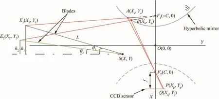
Fig.6 2D model of elevation measurement based on omnidirectional vision.

YAE1is the coordinate on line AE1.YAE2is the coordinate on line AE2.The equation of line AE1and AE2is written as follows.

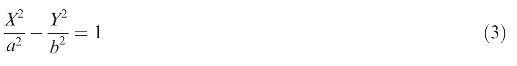
Set the equation of hyperbola is
We can get the Eq.(4)

where c is the focal length of the hyperbola.Set the A0,B0and C0donate the coef ficients,respectively.

We can obtain the reasonable solution of Xawhich is shown in Eq.(6)

Considering the Eq.(7)

The relation between the spacial position and image pixels is shown in Eq.(8):

We extend the 2D word to 3D space as shown in Fig.7(a),set any length |E1-E2| with the E1(X1,Y1,Z1) and E2(X2,Y2,Z2),the pitching and azimuth angles are α and θ,respectively.The number of pixels associated with the vertical distance of|E1-E2|is shown in Fig.7(b).
3.3.Model and calibration of omnidirectional vision system
In Section 3.2.,the elevation measurement approach is obtained by calculating the number of pixels associated with the vertical distance of elevation.This intuitive method is simple and effective,but requires precise knowledge of the installation parameters such as the coordinates of hinges of the blade and the coordinates of vision system center.Since the catadioptric omnidirectional vision system consists of a hyperbolic mirror and a perspective camera,it is always difficult to obtain precisely those mounting parameters.
In order to achieve a successful measurement,the singleview,omnidirectional-camera calibration algorithm proposed by Mei and Rives10is employed,in which camera lens distortion is introduced into the projection imaging process and the installation error of the structure is compensated.The calibration method is available online as an Open Source toolbox,which can save time and effort.Moreover,in addition to the methods evaluated in Puig et al’s research,18Mei and Rives’method provided the best results with respect to catadioptric-omnidirectional systems.We also include some modifications in this approach and subsequently use them to calculate the external parameters between camera and the planar grids pasted on the blades.
The transformations of this model about the coordinates are shown in Fig.8.The omnidirectional-camera coordinate system is the same as the mirror coordinate system,and the origin of the coordinate system is the internal focus of the mirror.Based on the uni fied sphere imaging model,19the transformation from sphere center coordinates to equivalent projection coordinate is the same as the transformation from re flection mirror coordinates and perspective camera coordinate.
3.3.1.Uni fied sphere imaging model
Nayar and Baker used mathematical formulas to prove that a single-viewpoint catadioptric-omnidirectional system mirror section must be a quadratic curve.20Geyer and Daniilidis19also demonstrated that a central catadioptric system was coincident with the unified sphere-imaging model.The uni fied sphere-imaging model projection process isolates the nonlinear transformation from the projection,substantially simplifying the subsequentanalysis and calculation.21The unified sphere-imaging model is shown in Fig.9.Cmand Cprepresent the originsofthemirror and panoramiccoordinates,respectively.

Fig.7 3D model of elevation measurement based on omnidirectional vision.

Fig.8 Coordinate system of the omnidirectional-camera calibration model.
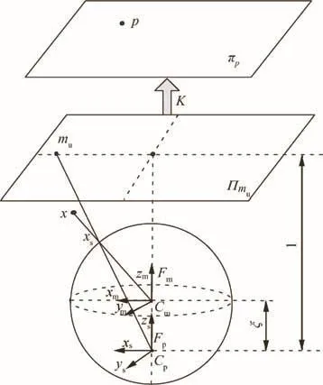
Fig.9 Uni fied sphere imaging model.
Set the projection center to Cm,which is also the center of the uni fied sphere.Any points locating at the mirror coordinate system can be non-linearly mapped onto the unit sphere,as shown in Eq.(9).

When the projection center is shifted to Cp=(0,0,ξ),we can get

Set the projection center to Cp,the point on the sphere is mapped to the plane Πmuwhich is point mu.

Finally,the points on the plane Πmuare mapped to the image plane πpas described in Eq.(12).

where the primary point is(uo,vo)and the tilt factor is α;[f1,f2]is the focal length.In order to facilitate the calculation,set the γi=fiη.
3.3.2.Omnidirectional vision system calibration
To compensate for mounting errors and lens aberrations,an additional distortion equation is introduced in the sphere projection model.Five parameters are involved in the actual projection model:
(1)External parameters

(2)Transformation of mirror projection
As mentioned above,H represents the nonlinear projection equation,and V2=[ξ]represents the unknown variable of the mirror which only relates to the h(xs).
(3)Distortion
Installation errors and radical distortions are two of the primary distortions involved in our study.Image distortion in panoramic eccentricity is caused by misalignment between the mirror and the camera,which is similar to the deformation of the lens group in the perspective vision system.We employ three parameters to describe the radical distortion and two parameters to describe the tangential distortion:


Set D is the distortion vector,and the distortion variables are V3=[k1,k2,k3,k4,k5].
(4)Model of perspective camera
The perspective projection model is built based on the pinhole model;the camera projection matrix is shown as follows:

where V4=[α,γ1,γ2,u0,v0].
(5)The projection matrix
The set G is the final projection equation,with eighteen parameters involved.

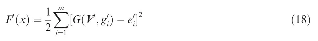
If there are m corner points in the pattern,the coordinate of the point is g corresponding to the image coordinate e,and then the maximum likelihood solution can be obtained by Eq.(17).
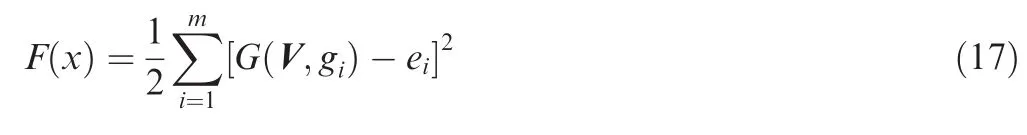
where the G(V,gi)is the projection of the ith corner point.The L-M algorithm is employed to deal with this typical nonlinear optimization issue.It is superior to simple gradient descent and other conjugate gradient methods on a wide variety of problems.
3.3.3.Calculation of extrinsic parameters
In Eq.(17),the omnidirectional vision internal parameters obtained in the calibration process is taken as constants.The coordinates of the pattern in the mirror coordinates is obtained in Eq.(19)in case the extrinsic parameters V′is solved.

3.4.Model of elevation measurement

Fig.10 Model of elevation measurement based on omnidirectional vision system.
In the process of elevation measurement based on the omnidirectional vision system,some 2 by 7 pattern boards are used whose lattice size is 30 mm×28 mm.First,the omnidirectional internal parameters and distortion are obtained by calibration,and then the projection matrix P of each blade between the pattern and the mirror coordinates is calculated.The elevation measurement model based on omnidirectional vision system is shown in Fig.10.In order to get the relative elevation between the blades,it is necessary to con firm the zero reference plane in advance.Let m1,m2,m3be the points at each blade pattern respectively.If the elevation difference of any two blades is zero,the m1,m2,m3lie in the same plane which is called the zero reference plane.The equation for this plane in the coordinates of the mirror is denoted by[nx,ny,nz,d0]·[x,y,z,1]T=0 and the unit normal vector of this plane is denoted by ¯n=[nx,ny,nz].Therefore,the elevation difference of m1,m2,m3can be obtained by separately calculating the distance difference along the normal vector.Convert the mirror coordinatestowheremeans that the new coordinate plane is parallel to the zero reference plane.The relation between the two coordinates is described by Eqs.(20)and(21).
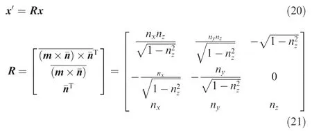
where m=[0,0,1];x¯is the unit vector;the elevation difference between the two blades is calculated by Eqs.(22)and(23).

4.Evaluation of measurement uncertainty
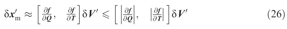
According to the existing definition given in Ref.23,the measurement result must include a specification of the uncertainty of the estimate.In our study,the precise ofin Eq.(19)is related to the seven parameters as follows.


where
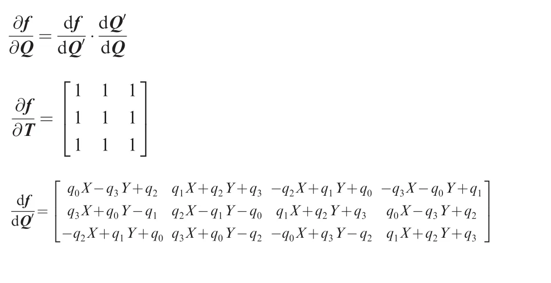
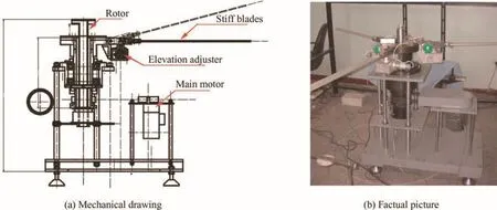
Fig.11 Simulated blade test system(mechanical drawing and factual picture).

Fig.12 Panoramic vision system mounted on the rotor.

Table 1 Calibration results of the omnidirectional vision system.


Fig.13 Images of pattern board on the blades.
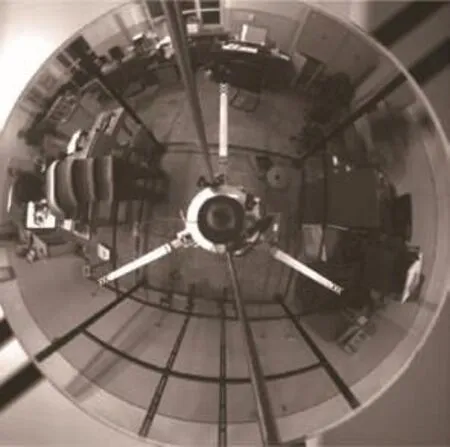
Fig.14 Omnidirectional image include all the blades.

The derivation of Eq.(27)considering that

So
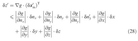

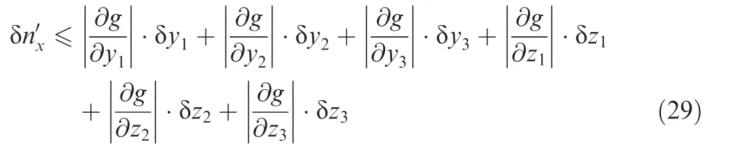

After the δnyand δnzare solved,we can get the error of z′.Theandare equal probability distribution,then

5.Experimental results and analysis
5.1.Equipment
In order to verify the performance of the novel approach based on the omnidirectional vision system,a series of experiments were carried out on the simulation blades test system and thepractical blade test tower.Our laboratory established a simulated blade test system consisting of a rotor,stiff blades,an elevation adjuster and a main motor,as shown in Fig.11.The elevation of the stiff blades can be adjusted by the elevation adjuster in both rotary and static modes.The test system also included a laser measurement system12whose data was used as ground truth to evaluate our measure results.
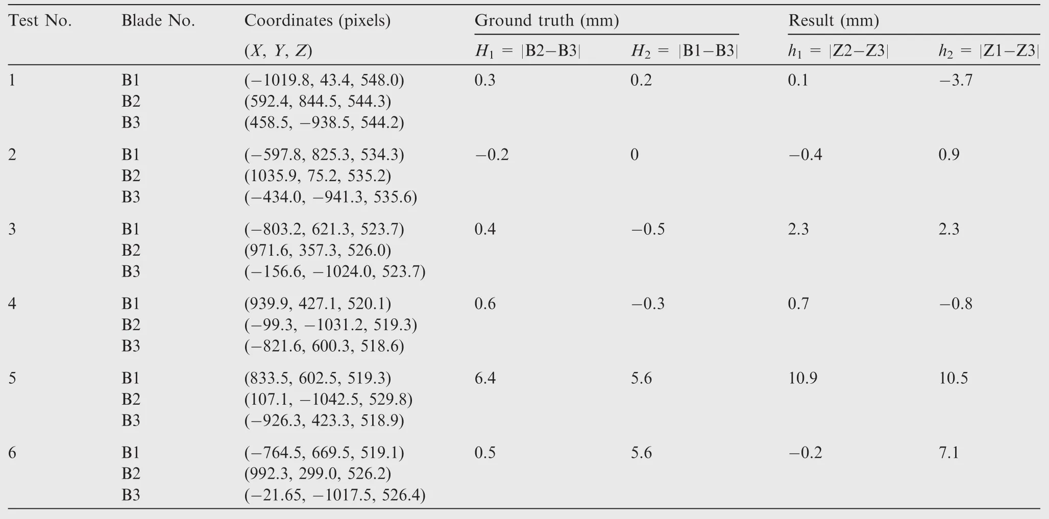
Table 2 Experimental results on the simulated test system.
The catadioptric-omnidirectional vision system used in these experiments is developed as shown in Fig.12.The omnidirectional vision system was consisted of a hyperbolic mirror,a high resolution camera,a compact computer and the battery.The camera base was equipped with a 3-degree-of-freedom adjustment device.By using a single-view-point-constraint determination method24and by adjusting the device,the single-view-point constraint was considered to be satisfied during camera-mirror assembly.The captured images were stored in the compact computer which is real-time downloaded through electrical slip ring communication system.It is equipped on the rotation axis.The eccentricity of the mirror was ε=0.92848 and ξ =0.9285,which was provided by the manufacturer.The camera model was IMPERX IPX-16M3T-GC and the resolution of image was 3248×3248 pixels,which was provided by the manufacturer.
5.2.Omnidirectional vision system calibration
The omnidirectional vision system was calibrated based on the calibration method.10The calibration results are shown in Table 1.
5.3.Experiments on the simulated blade test system

Fig.15 Experiment on the practical blades test tower and captured image.

Table 3 Experimental results in practical blades test tower.
The pattern boards were pasted on the blades,as described in Fig.13.The omnidirectional image captured by the vision device is show in Fig.14.The experimental results is recorded in Table 2.The h1of elevation difference between Blade1(B1)and Blade2(B2)was calculated through|Z2-Z3|and the h1was obtained in the same way.The real elevation differences obtained by the laser system are taken as the ground truth for verifying the experimental results.The maximum error was not more than 5 mm,which demonstrates the outstanding measurement performance using omnidirectional vision technique.
5.4.Experiments on the practical blades test tower
Other experiments were also developed to further verify the effectiveness of this method.We carried out this test on the practical blades test tower as shown in Fig.15.The experimental data is recorded in Table 3.By analyzing the test data,the measurement results are also reasonable.
6.Conclusion and prospect
In this paper,a novel blade elevation measurement approach is presented.Compared with the other state of the art methods,the method we proposed provides a simpler and more ef ficient way that requires neither a huge device nor a high frame rate cameras.A catadioptric-omnidirectional camera is mounted on the hub of helicopter and rotates with the blades.All of the blades are imaged at one time.The calibration model is obtained based on the uni fied sphere imaging model.The evaluation of uncertainty of the measurement of this method is conducted to demonstrate the validity of the approach.Compared with the existing methods,our method can obtain the elevation of all the blades at the same time,regardless of the position of the blades.This new measurement method is also flexible to put into effect regardless of the installation parameters.The experimental results clear evidence also manifest the effectiveness of this approach.In the near future,we will combine the helicopter attitude and heading measurement algorithms based on omnidirectional vision system with our algorithm to make our method more extensibility.
This study was supported in part by the National Natural Science Foundation of China(Nos.61673129,51674109).Natural Science Foundation of Heilongjiang Province of China(No.F201414).Harbin Application Research Funds(No.2016RQQXJ096).Fundamental Research Funds for the Central Universities(No.HEUCF041703).State Key Laboratory of Air Traffic Management System and Technology(No.SKLATM201708).
1.Jiang X,Zhao Q,Zhao G,Li P.Integrated optimization analyses of aerodynamic/stealth characteristics of helicopter rotor based on surrogate model.Chin J Aeronaut 2015;28(3):737–48.
2.Tian Y,Liu H,Luo M,Huang J.Non-uniform hybrid strategy for architecting and modeling flight vehicle focused system-of-systems operations.Chin J Aeronaut 2016;29(1):160–72.
3.Kehong L,Tan X,Liu G,Zhao C.Sensor selection of helicopter transmission systems based on physical model and sensitivity analysis.Chin J Aeronaut 2014;27(3):643–54.
4.Friedmann PP,Glaz B,Palacios R.A moderate deflection composite helicopter rotor blade model with an improved crosssectional analysis.Int J Solids Struct 2008;46(10):2186–200.
5.Sayed M,Kamel M.Stability study and control of helicopter blade flapping vibrations. Appl Math Model 2011;35(6):2820–37.
6.Nayar SK,Baker S.A theory of catadioptric image formation.IEEE international conference on computer vision;1998 Jan 4–7,Mumbai,India.Pisscataway(NJ):IEEE Press;1998.p.35–42.
7.Plagemann C,Stachniss C,Hess J,Endres F,Franklin N.A nonparametric learning approach to range sensing from omnidirectional vision.Robot Auton Syst 2010;58(6):762–72.
8.Mondrago´n IF,Campoy P,Martinez C,Olivares M.Omnidirectional vision applied to unmanned aerial vehicles(UAVs)attitude and heading estimation.Robot Auton Syst 2010;58(6):809–19.
9.Natraj A,Ly DS,Eynard D,Demonceaux C,Vasseur P.Omnidirectional vision for UAV:Applications to attitude,motion and altitude estimation for day and night conditions.J Intell Robot Syst 2013;69(1–4):459–73.
10.Mei C,Rives P.Single view point omnidirectional camera calibration from planar grids.IEEE international conference on robotics and automation,2007 Apr 10–14;Rome,Italy.Piscataway(NJ):IEEE Press;2007.p.3945–50.
11.Cai CT,Zhu QD,Lei LI.Design and realization of helicopter blade running elevation measurement system.J Harbin Eng Univ 2006;27(3):395–9[Chinese].
12.Jia G,Cai CT,Jiang M.The design and implementation of helicopter blades pyramid angle measurement system.Proceedings of the 2011 third international conference on measuring technology and mechatronics automation,2011 Jan 6–7,Washington D.C.,USA.Pisscataway(NJ):IEEE Press;2011.p.740–43.
13.Cai CT,Jiang M,Zhang F,Lin H.Fast camera calibration technology applied to helicopter blades pyramid angle measurement.2010 8th world congress on intelligent control and automation(WCICA);2010.p.704–8.
14.Lu J,Deng C,Cai CT,Jiang M.Taper measurement for helicopter rotor based on spot imaging method.Comput Meas Control 2011;19(7):1543–6[Chinese].
15.Li XM,Peng HX,Huang JP,Liu ZJ.Measure rotor track using universal track device(UTD).Helicop Tech 2007;14(1):50–4[Chinese].
16.Cao K,Chu Y.The Infra-red light measurement of helicopter blade.Meas Control Technol 1994;13(2):28–31[Chinese].
17.Nagy AE,Szakats I,Marita T,Nedevschi S.Development of an omnidirectional stereo vision system.IEEE international conference on intelligentcomputercommunication and processing(ICCP);2013 Sept 5–7;Cluj-Napoca.Piscataway(NJ):IEEE Press;2013.p.235–42.
18.Puig L,Bermu´dez J,Sturm P,Guerrero J.Calibration of omnidirectional cameras in practice:A comparison of methods.Comput Vis Image Understand 2012;116(1):120–37.
19.Geyer C,Daniilidis K.A unifying theory for central panoramic systems and practical implications.In:Vernon D,editor.Computer vision ECCV 2000.Berlin,Germany:Springer;2000.p.445–61.
20.Nayar SK,Baker S.A theory of catadioptric image formation.IEEE international conference on computer vision;1998 Jan 4–7,Mumbai,India.Piscataway(NJ):IEEE Press;1998.p.35–42.
21.Barreto JP,Araujo H.Issues on the geometry of central catadioptric image formation.Proceedings of the computer society conference on computer vision and pattern recognition;2001.p.422–7.
22.More´JJ.The Levenberg-Marquardt algorithm:Implementation and theory.Lect Notes Math 1978;630:105–16.
23.Beuchot M.International vocabulary of metrology–basic and general concepts and associated terms.Chem Int 2008;30(6):21–2.
24.Zhu QD,Zhang F,Li K,Jing L.On a new calibration method for single viewpoint constraint for catadioptric omnidirectional vision.Huazhong Univ Sci Tech 2010;38(7):115–8[Chinese].
5 October 2016;revised 1 November 2016;accepted 21 January 2017
Available online 14 October 2017
Ⓒ2017 Chinese Society of Aeronautics and Astronautics.Production and hosting by Elsevier Ltd.This is an open access article under the CCBY-NC-ND license(http://creativecommons.org/licenses/by-nc-nd/4.0/).
*Corresponding author.
E-mail addresses:caichengtao@hrbeu.edu.cn(C.CAI),wengxiangyu@hrbeu.edu.cn(X.WENG).
Peer review under responsibility of Editorial Committee of CJA.
 CHINESE JOURNAL OF AERONAUTICS2017年6期
- CHINESE JOURNAL OF AERONAUTICS的其它文章
- A general method for closed-loop inverse simulation of helicopter maneuver flight
- Numerical simulation of a cabin ventilation subsystem in a space station oriented real-time system
- Parametric analyses on dynamic stall control of rotor airfoil via synthetic jet
- Effect of particle size and oxygen content on ignition and combustion of aluminum particles
- Effects of axial gap and nozzle distribution on aerodynamic forces of a supersonic partial-admission turbine
- Effect of a transverse plasma jet on a shock wave induced by a ramp