
An optimal method of posture adjustment in aircraft fuselage joining assembly with engineering constraints
2017-12-22 06:24YuanLILiZHANGYanzhongWANG
CHINESE JOURNAL OF AERONAUTICS 2017年6期
Yuan LI,Li ZHANG,Yanzhong WANG
School of Mechanical Engineering and Automation,Beihang University,Beijing 100083,China
An optimal method of posture adjustment in aircraft fuselage joining assembly with engineering constraints
Yuan LI,Li ZHANG*,Yanzhong WANG
School of Mechanical Engineering and Automation,Beihang University,Beijing 100083,China
Aircraft assembly; Engineering constraint; Least-squares method; Multi-objective optimization; Point registration; Posture adjustment
Posture of an aircraft fuselage can be evaluated based on the coordinate values of measure points fixed on the aircraft fuselage in aircraft final assembly.Posture adjustment is carried out by rotation and translation of the aircraft fuselage to make sure that the actual coordinate values of the measure points are coincided with the theoretical ones read from the computer aided design(CAD)model.The point registration method of posture adjustment without considering engineering constraints may cause out-of-tolerance for some engineering constraints.Hence,engineering constraints such as plane symmetry of two points,as well as coplanar and collinear of the multipoint should be considered in the new optimal method of posture adjustment in aircraft fuselage joining assembly.Based on the point registration model,a multi-objective optimization model of posture adjustment considering engineering constraints including collinear,coplanar,and symmetry constraints is established and represented by a uniform vector function.The weights of constraint conditions can be set freely in the optimization model to re flect the importance of the corresponding constraints in aircraft fuselage joining assembly.The rotation and translation parameters of posture adjustment are obtained by the proposed multi-objective optimization algorithm based on the Gauss-Newton method.Results of an example of aircraft fuselage joining assembly show that constraint errors of posture adjustment obtained by the multi-objective optimization model are not out of tolerance for design constraint errors and satisfy the requirement of aircraft fuselage joining assembly.
1.Introduction
Aircraft joining assembly including fuselage joining,wingfuselage joining,and tail-fuselage joining is one of the key processes of aircraft final assembly,and determines the manufacturing quality of aircraft directly.1Traditional aircraft joining assembly is mainly dependent on special-type frames for positioning and clamping.To ensure that all the constraint errors are in the design ranges,large aircraft components are located on a bracket or trailer platform and adjusted manually to achieve the optimal posture,which has led to low precision,poor versatility,and low assembly ef ficiency.With the development of computer control technology,an automatic joining technology of aircraft assembly based on digital flexible assembly technology has been established.2,3A digital flexible joining system in aircraft assembly has been applied to complete the joining assembly process including posture measurement,4,5posture adjustment calculation,6and motion control7,8automatically,which greatly improves accuracy and ef ficiency of aircraft assembly.
The real-time posture of an aircraft fuselage segment can be evaluated based on the actual coordinates of measure points located in the key positions of the aircraft fuselage,which are obtained by measurement systems such as laser tracker and the indoor global positioning system(iGPS).The actual posture of the aircraft fuselage maybe deviates from the theoretical one read from the computer aided design(CAD)model.The purposes of posture adjustment calculation are to obtain the optimal posture of the aircraft fuselage segment which should be coincident with the theoretical one by rotating and translating the aircraft fuselage segment,and to ensure the smallest difference between the actual and theoretical coordinates of the measure points.9Study of the posture adjustment method in aircraft assembly has attracted attentions of many scholars.Ke et al.10,11proposed a posture adjustment method for joining fuselage sections and wings in digital aircraft assembly based on the POGO sticks designed by themselves.Li et al.12,13developed a posture adjustment method in the wing-body assembly using the particle swarm optimization(PSO)algorithm and iterative closest point(ICP)algorithm,which had been applied in an actual assembly line and proven to be economic and time-saving with high accuracy.However,the proposed posture adjustment models are point registration models,and engineering constraints which are required in aircraft joining assembly aren’t considered in these models,which would cause out-of-tolerance for some engineering constraints and not satisfy the requirement of engineering constraints in aircraft fuselage joining assembly.14The way to solve this problem is to model engineering constraint conditions in the optimization model.15
Considering engineering constraints such as collinear,coplanar,and symmetry constraints,a multi-objective optimization model of posture adjustment in aircraft fuselage joining assembly is proposed in this paper.Based on the point registration model,the multi-objective model considering collinear,coplanar,and symmetry constraints is established and represented by a uniform vector function.A multi-objective optimization algorithm based on the Gauss-Newton method is used to solve this model.The six rotation and translation parameters of posture adjustment are obtained.Weights of constraints in the optimization model can be set freely to re flect the importance of constraints in aircraft fuselage joining assembly.An example is discussed in detail to illustrate that constraint errors of posture adjustment obtained by the multi-objective optimization model are not out of tolerance for engineering constraints and satisfy the requirement of aircraft fuselage joining assembly.The rotation and translation parameters obtained will be the input data of the posture alignment system.
2.Point registration model of posture adjustment
The point registration model applied in posture adjustment of aircraft assembly commonly depends on the quaternion algorithm,16singular value decomposition(SVD)algorithm,17,18orthogonal matrix algorithm,19and ICP algorithm.20–22All these optimal algorithms are based on the least square method.Let θx,θy,θz,gx,gy,gzbe the rotation and translation parameters that represent rotating an aircraft fuselage θxradian counterclockwise about x axis,θyradian about y axis,and θzradian about z axis,and then translating it gx,gy,gzalone x,y,z axes,respectively.The transformation matrix M of rotation and translation can be obtained according to geometry theory,as shown in Eq.(A1).
Let x1i=[x1i,y1i,z1i,1]T(i=1,2,...,n1)be the actual coordinates of measure points by homogeneous coordinate representation,which would be obtained by measurement systems,and X1i(i=1,2,...,n1)be their theoretical coordinates read from the CAD model,in which n1is the number of measure points in the point registration model.After rotation and translation of the aircraft fuselage segment,the new coordinatesof the measure points in the aircraft fuselage segment corresponding to x1iare obtained as

The actual coordinates x1ishould be coincident with the theoretical coordinates X1iafter rotation and translation of the aircraft fuselage segment,and based on the least square method,the objective function of the point registration model is established as the sum of squares of the distances between the actual and nominal coordinatesand X1i.

where w1=[w1i](i=1,2,...,n1)is the weight vector of the measure points for the point registration constraint.Eq.(2)is represented as a vector function with all variables θx, θy,θz,gx,gy,gzin matrix M.The optimal rotation and translation parameters would be achieved at the minimum value of the objective function.
3.Multi-objective optimization model with engineering constraints
Aircraft fuselages are joined with aircraft wings and tails in aircraft final assembly,so engineering constraints such as the symmetry constraint as well as the collinear and coplanar constraints are required.
3.1.Collinear constraint

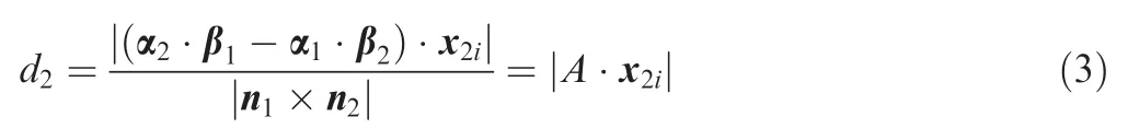
After rotation and translation of the aircraft fuselage segment,the actual coordinates of the measure points corresponding to x2iwould beThe necessary and suf ficient condition for a point being on a straight line is that the distance from the point to the straight line is zero.Therefore,the objective function for the collinear constraint is obtained as follows:

where w2=[w2i](i=1,2,...,n2)is the weight vector of the measure points for the collinear constraint.Eq.(4)represented as a vector function evaluates the constraint error of the measure points for the collinear constraint.
3.2.Coplanar constraint

The new coordinates of the measure points for the coplanar constraint is represented asafter rotation and translation of the aircraft fuselage segment.The objective function for the coplanar constraint is obtained as follows:

where w3=[w3i](i=1,2,...,n3)is the weight vector of measure points for the coplanar constraint.Eq.(6)evaluates the constraint error of the measure points for the coplanar constraint and is represented as a vector function.
3.3.Symmetry constraint
Aircraft wings and tails should be symmetric in aircraft final assembly.Let x41i,x42i(i=1,2,...,n4)be the actual coordinates of the measure points which should be symmetric about the theoretical planeafter rotation and translation of the aircraft fuselage segment,in which n4is the number of measure points for the symmetry constraint.According to geometry theory,ifthe straightline connecting two points is perpendicular to plane C2and their midpoint is located in plane C2,then the two points will be symmetric about plane C2.The objective function for the symmetry constraint is constructed as follows:

where w4=[w4i](i=1,2,...,n4)is the weight vector of measure points for the symmetry constraint.The first part of Eq.(7)is the squares of the distance from the midpoint of the connecting line to plane C2.The second part is the difference between the length of the connecting line and its projection in the normal of plane C2,which evaluates the perpendicularity of the connecting line to the symmetric plane.Eq.(7)evaluates the constraint error of the measure points for the symmetry constraint.
3.4.Multi-objective optimization model
Based on Eqs.(2),(4),(6),and(7),the objective function including engineer constraints such as collinear,coplanar,and symmetry constraints based on the point registration model is obtained as follows:

where w=[w1,w2,w3,w4]is the weight vector of the measure points for all the constraints.Parts of the objective function Σ1,Σ2,Σ3,Σ4are represented by the uniform vector function with all the variables θx,θy,θz,gx,gy,gzin matrix M,so it’s simple to derive the partial derivatives of Eq.(8)based on the derivatives of matrix M.
4.Numerical solution of the optimization model
The optimization model of posture adjustment is described by a nonlinear function with six variables.A numerical method is put forward to solve this optimization model.23According to the intermediate value theorem of a continuous function,when the partial derivatives of the objective function are zero,the extremum of the optimization function would be obtained.Therefore,the optimization model is translated to a nonlinear system with six equations as

Eq.(9)has six variables:θx,θy,θz,gx,gy,gz.The solution process is complex and sensitive to the initial values,so it’s better to determine the approximate range of the solution by a point registration optimization algorithm.
4.1.Point registration optimization algorithm
In order to reduce the dif ficulty of obtaining the numerical solution of the point registration optimization model,the center-of-gravity registration method is used to determine the translation parameters gx,gy,gzand reduce the number of unknown variables.Then the Gauss-Newton method is applied to solve the nonlinear point registration optimization model with the same center of gravity and determine the rotation parameters θx,θy,θz.
The actual and theoretical coordinate values g1and G1of the centers of gravity of the measure points for the point registration constraint can be represented as follows,respectively:

The center of gravity of the actual coordinates should be coincided with that of the theoretical ones after translation of the aircraft fuselage segment.Then the initial translation parameters gx0,gy0,gz0are obtained as

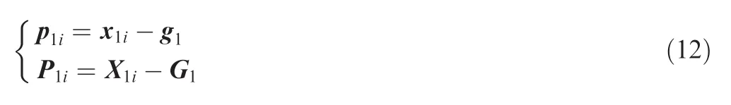
The actual and theoretical coordinates p1i,P1i(i=1,2,...,n1)of the measure points relative to their centers of gravity can be represented,respectively,as
After rotation of the aircraft fuselage segment around its actual center of gravity,the actual coordinates of the measure points should be coincided with the theoretical ones.According to the least square method,the optimization function is established as follows:

where L is the rotation matrix with the rotation parameters θx,θy,θz.The SVD method has been used to solve the point registration model in the literature.14However,because of the possible failure of the SVD method,a numerical method is used to obtain the minimum of Eq.(13).The optimization problem can be translated to solve the partial derivative equations of the optimization function Eq.(13)as

4.2.Multi-objective optimization algorithm
The solution of Eq.(9)is the extremum of the optimal objective function Eq.(8)in the neighborhood of the initial values,which may not be the minimum value.Therefore,the iterative method is applied to obtain the optimal results with the global constraint error as its end condition in the iteration process.The speci fic process is shown in Fig.1.
Step.1 Determine the initial value of the iterative method based on the point registration optimization algorithm referred in Section 4.1.The initial parameters t0=[θx0,θy0,θz0,gx0,gy0,gz0]satisfying the point registration constraint are obtained and will determine the approximate range of the numerical solution of the multi-objective optimization model;

Fig.1 Multi-objective optimization algorithm of posture adjustment in aircraft fuselage joining assembly.
Step.2 Solve Eq.(9)by using the Gauss-Newton method with the initial value t0.The solution t1can be obtained,and the intermediate transformation matrix M1is calculated.The numerical solution of nonlinear Eq.(9)is very sensitive to the initial value,so the initial value t0obtained by the point registration optimization algorithm can be used to accelerate the convergence rate and improve the computational ef ficiency;
Step.3 Calculate the new coordinates of the measure pointsand the new transformation matrixwhereis the intermediate coordinate of the measure points obtained in the kth iteration.The total constraint error Σ can be calculated by Eq.(8).The iteration process could be ended when the total constraint error Σ is less than the total tolerance δ of the constraint conditions for several sequence iterations N<100;Otherwise,repeat Step.1;Step.4 Change the weight vector w and repeat the iteration process if the iteration doesn’t converge when the number of iteration loops is more than 100.
The final transformation matrix M will be obtained,and the rotation and translation parameters θx, θy, θy,gx,gy,gzcan be calculated by

where Mij(i,j=1,2,3,4)are the elements of the transformation matrix M.
5.Example and discussion
An example of posture adjustment in aircraft fuselage joining assembly is shown in Fig.2.Points 1–6 for the point registration constraint are the measure points located on the joints of an aircraft fuselage segment which could be jointed with another aircraft fuselage segment.Points 7–8 and points 9–10 for the coplanar constraint are set in two seat tracks,respectively.The positions of the seat tracks are determined by lines l1,l2,so points 7–8 and points 9–10 should be in lines l1,l2,respectively.Points 11–13 are located on the cabin floor represented by plane C1for the coplanar constraint.Points 14–15 are the measure points set on the joints of fuselage wing jointing,and required to be symmetrical about plane C2.
The theoretical coordinates of the measure points listed in Table 1 are read from the CAD model.Lines l1and l2are determined by the theoretical coordinates of points 7–8 and points 9–10,respectively.Planes C1and C2are determined by the theoretical coordinates of points 11–13 and points 14–15,respectively.Assume that the actual posture of the aircraft fuselage segment is obtained by rotating the theoretical onearound x,y,z axes counterclockwise,and then translatingalong x,y,z axes,respectively.Here,=(π/13, π/13, π/13,12.34,-20.67,706.36).The translation matrix M′from the theoretical posture to the actual one can be calculated by Eq.(A1),and the actual coordinates of measure points could be obtained by Eq.(1)which also listed in Table 1.
Theoretically,the transformation matrix from the actual posture to the theoretical one should be M=(M′)-1.According to Eq.(15),the theoretical parameters of rotation and translation from the actual posture to the theoretical one should be t′=[-0.1058, 0.6601, -0.1466, 409.8730,-115.1963,-564.1436].

Fig.2 Sketch of posture adjustment in aircraft fuselage joining assembly.

Table 1 Theoretical and actual coordinates of measure points.
5.1.Posture adjustment results without errors
If there are no errors in the actual coordinates of the measure points theoretically,the transformation matrix M from the actual posture to the theoretical one is obtained by the multi-objective optimization algorithm as follows:

According to Eq.(15),the actual rotation and translation parameters are obtained as t=[-0.1058,-0.6601,-0.1466,409.8730,-115.1963,564.1436],which are equal to the theoretical parameters t′.The constraint errors shown in Table 2 indicate that the actual posture will be perfectly coincided with the theoretical posture after posture adjustment.Therefore,the multi-objective optimization algorithm is accurate in posture adjustment of aircraft fuselage joining assembly when there are no errors in the actual coordinates of the measure points.
5.2.Posture adjustment results with errors
However,the actual coordinates of the measure points in aircraft fuselage segment assembly contain errors including measurement,manufacturing,and assembly errors.Assuming that the total error of the actual coordinates of the measure points is within the scope of±0.5 mm,the white noise with a Gaussian distribution(μ=0,σ=0.5)representing the errors is added into the actual coordinates in Table 1,and new actual coordinates with errors are obtained.
The requirements of posture adjustment are that the distance between the actual and theoretical coordinates of the measured points is not more than 0.8 mm for the point registration constraint,the distance from the measure points to the theoretical line for the collinear constraint is not more than 0.5 mm,the distance from the measure points to the theoretical plane for the coplanar constraint is not more than 0.5 mm,and the symmetrical constraint error is not more than 0.2 mm.When the point registration constraint is required only,the weight vector could be w=[w1,w2,w3,w4]=[1,0,0,0].The results of posture adjustment without considering engineering constraints are shown in Table 3.
Results in Table 3 show that the posture of an aircraft fuselage without considering engineering constraints is optimal for the point registration constraint but out of tolerance for coplanar and symmetry constraints,which doesn’t satisfy the requirements of posture adjustment in aircraft fuselage joining assembly.Considering engineering constraints,the multiobjective optimization algorithm of posture adjustment is carried out and the results are shown in Table 4.It’s found that the constraint errors satisfy both of the requirements of the point registration constraint and engineering constraints in aircraft fuselage segment assembly.
5.3.Effects of the weight vector on constraint errors
The weight vector of posture adjustment in Table 4 is w=[w1,w2,w3,w4]=[1,10,10,5].The weights w1,w2,w3,w4of constraint conditions re flect the importance of the corresponding constraints for posture adjustment in aircraft fuselage segmentassembly.Different constraint weights can achieve different optimization results.Results in Table 5 show the effects of constraint weights on constraint errors obtained by the multi-objective optimization algorithm.The greater weight of one constraint in the multi-objective optimization model,the better performance of this constraint in the posture adjustment result obtained by the multi-objective optimization algorithm.It should be noted that the posture adjustment result is optimal for one constraint but not for the others,so it’s better to set the weights of constraints with considering all constraints synthetically to make sure that the optimal posture adjustment results will satisfy all requirements of constraint conditions in aircraft assembly.When requirement of constraints can’t be satisfied whatever weights are,the possible reason is that the errors of some measure points are too large to obtain a convergence solution.

Table 2 Constraint errors of postures adjustment without errors in the measure points.

Table 3 Results of posture adjustment without engineering constraints.

Table 4 Results of posture adjustment with engineering constraints.

Table 5 Effects of the weight vector w on constraint errors.
6.Conclusions
The optimal method of posture adjustment in aircraft fuselage joining assembly with considerations of engineering constraints is proposed in this paper,and conclusions are obtained as follows:
(1)Based on a point registration optimization model,a multi-objective optimization model of posture adjustment is established with considering engineering constraints including collinear,coplanar,and symmetry constraints and represented by a uniform vector function.The rotation and translation parameters of the optimal posture are obtained by the multi-objective optimization algorithm based on the Gauss-Newton method,which would be the input data of a posture alignment system.
(2)Compared to the point registration model,the multiobjective optimization model considering engineering constraints has better performance in posture adjustment in the aircraft fuselage joining assembly.
(3)The weights of constraint conditions could affect the results of the multi-objective optimization model.By choosing appropriate weights of constraint conditions,the optimal posture of an aircraft fuselage will be obtained to satisfy the requirements of constraint conditions and avoid out-of-tolerance of constraint conditions in aircraft fuselage joining assembly.
Acknowledgement
The authors would like to express their gratitude for the financial support of the National Science and Technology Major Project(No.2014ZX04001-081).
Appendix A
The transformation matrix M with rotation and translation parameters θx,θy,θz,gx,gy,gzcan be represented as follows:

The partial derivatives of the multi-objective optimization function can be represented as the following vector function:

1.Webb P,Eastwood S,Jayaweera N,Chen Y.Automated aerostructure assembly.Indust Robot:Int J 2005;32(5):383–7.
2.Jamshidi J,Kayani A,Iravani P,Maropoulos PG,Summers MD.Manufacturing and assembly automation by integrated metrology systems for aircraft wing fabrication.Proc Inst Mech Eng B:Eng Manuf 2010;224(1):25–36.
3.Hartmann J,Meeker C,Weiier M.Determinate asssembly of tooling allows concurrent design of Airbus wings and major assembly fixtures.SAE Paper:2004-01-2832.
4.Liu S,Luo Z,Tan G,Nan YE,Zhang L.3D Measurement and quality evaluation for complex aircraft assembles.Acta Aeronautica et Astronautica Sinica 2013;34(2):409–18[Chinese].
5.Chen ZH,Du FZ,Tang XQ.Research on uncertainty in measurement assisted alignment in aircraft assembly.Chin J Aeronaut 2013;26(6):1568–76.
6.Zhu YG,Huang XG,Fang WB,Li SG.Trajectory planning algorithm based on quaternion for 6-DOF aircraft wing automatic position and pose adjustment method.Chin J Aeronaut 2010;23(6):707–14.
7.Wei T,Mei D,Li P,Zeng YF,Hong P,Zhou W.Determination of optimal samples for robot calibration based on error similarity.Chin J Aeronaut 2015;28(3):946–53.
8.Fan YQ.Modern aircraft manufacturing technology.Beijing:Beihang University Press;2001[Chinese].
9.Qiu BG,Jiang JX,Bi YB,Fang Q,Wang Q,Zhan JC,et al.Posture alignment and joining test system for large aircraft fuselages.Acta Aeronautica etAstronautica Sinica 2011;32(5):908–19[Chinese].
10.Guo ZM,Jiang JX,Ke YL.Posture alignment for large aircraft parts based on three POGO sticks distributed support.Acta Aeronautica et Astronautica Sinica 2009;30(7):1319–24[Chinese].
11.Zhang B,Yao BG,Ke YL.A novel posture alignment system for aircraftwing assembly.J Zhejiang Univ.SciA 2009;10(11):1624–30.
12.Yuan L,Jie Z,Tang WB,Jiang SS.A simple mechanical measurement system for the posture evaluation of wing components using the PSO and ICP algorithms.Assembly Autom 2015;35(1):104–13.
13.Tang WB,Li Y,Yu JF,Zhang J,Sun YL.A posture evaluation method for aircraft wing based on a simple measurement system.Proc Inst Mech Eng,B:Eng Manuf 2013;227(4):627–30.
14.Yu CJ,Li JX,Yu FJ,Ke YL,Qin LG,Chen XL,et al.3D points registration algorithm with engineering constraints.J Mech Eng 2010;46(5):183–90[Chinese].
15.Guan G,Lin Y,Shen M,Ji ZS.Point registration algorithm for hull block measurement with engineering constraints.J Harbin Eng Univ 2013;34(5):541–8[Chinese].
16.Berthold K,Horn P.Closed-form solution of absolute orientation using unit quaternion.J Opt Soc Am A 1987;4(4):629–42.
17.Umeyamas S.Least-squares estimation of transformation parameters between two point patterns.Trans Pattern Anal Mach Intell 1991;13(4):376–80.
18.Shen M,Guan G,Wang HZ.Automatic registration of hull blocks point clouds based on SVD.In:Proceedings of the 2nd international conference on information technology and scienti fic management;2011.p.2143–5.
19.Horn BKP,Hilden HM,Negahdaripour S.Closed-form solution of absolute orientation using orthonormal matrices.J Opt Soc Am A 1988;5(7):1127–35.
20.Chetverikov D,Stepanov D,Krsek P.Robust Euclidean alignment of 3D point sets:the trimmed iterative closest point algorithm.Image Vis Comput 2005;23(3):299–309.
21.Almhdie A,Ger C,Deriche M,Roger E.3D registration using a new implementation of the ICP algorithm based on a comprehensive look up matrix:application to medical imaging.Pattern Recogn Lett 2007;28(12):1523–33.
22.Hou Y,Li Y,Zhang J,Tang WB,Jiang SS.A simple mechanical measurement system for the posture evaluation of wing components using the PSO and ICP algorithms.Assembly Autom 2015;35(1):104–13.
23.Hill A,Cootes TF,Taylor CJ.Least-squares solution of absolute orientation with non-scalar weights in pattern recognition.Int Conf Pattern Recog,August 25–29,1996.
8 November 2016;revised 11 December 2016;accepted 17 March 2017
Available online 8 June 2017
Ⓒ2017 Production and hosting by Elsevier Ltd.on behalf of Chinese Society of Aeronautics and Astronautics.This is an open access article under the CC BY-NC-ND license(http://creativecommons.org/licenses/by-nc-nd/4.0/).
*Corresponding author.
E-mail address:gracejune@buaa.edu.cn(L.ZHANG).
Peer review under responsibility of Editorial Committee of CJA.
 CHINESE JOURNAL OF AERONAUTICS2017年6期
- CHINESE JOURNAL OF AERONAUTICS的其它文章
- A general method for closed-loop inverse simulation of helicopter maneuver flight
- Numerical simulation of a cabin ventilation subsystem in a space station oriented real-time system
- Parametric analyses on dynamic stall control of rotor airfoil via synthetic jet
- Effect of particle size and oxygen content on ignition and combustion of aluminum particles
- Effects of axial gap and nozzle distribution on aerodynamic forces of a supersonic partial-admission turbine
- Effect of a transverse plasma jet on a shock wave induced by a ramp