
Vehicle Dynamic State Estimation:State of the Art Schemes and Perspectives
2018-05-02 07:10HongyanGuoDongpuCaoHongChenSeniorChenLvHuajiWangandSiqiYang
Hongyan Guo,Dongpu Cao,Hong Chen,Senior Chen Lv,Huaji Wang,and Siqi Yang
I.INTRODUCTION
W ITH the rapid development of automated driving[1],[2],parallel unmanned systems[3]-[5],control and computer science[6],[7],intelligent transportation systems(ITS)[8],[9],advanced driver assistance systems(ADAS),vehicle handling stability and active safety have increasingly been promoted since the past century.As a result,various ADAS and vehicle stability control systems have been developed,such as the anti-lock braking system(ABS)[10],[11],adaptive cruise system[12]and traction control system(TCS)[13],[14],which are based on vehicle longitudinal control;the electronic stability program(ESP)[15],[16]and active front steering(AFS)[17],which are concerned with lateral stability;and active suspension control(ASC)[18],[19]and active body control(ABC)[20],which emphasizes vehicle vertical control.Vehicle handling stability and active safety are effectively improved with the help of these systems,and consequently,vehicles have become safer to drive and the number of fatal accidents has declined[21].
TABLE INOMENCLATURE
However,the implementation of those automotive stability control systems,especially for connected vehicles and automated driven vehicles,depends on accurate vehicle dynamic state information[22].Conventionally,vehicle dynamic state information is directly measured by onboard sensors that are sufficiently inexpensive for mass-production vehicles.How-ever,due to the extremely complicated running conditions,the accuracy of these sensors is relatively low and does not satisfy the requirements of vehicle active safety control systems[23].In addition,considering the cost of mass-production vehicles,many sensors are too expensive to equip,such as inertial navigation sensors(INS),global positioning system(GPS),and global navigation satellite system(GNSS)[22],[24].
The existing problems of low precision under some extreme running conditions and the high price of some onboard sensors have become a bottleneck to obtain precise and complete vehicle dynamic state information.Thus,the incomplete information about vehicle dynamic states greatly limits the development of ADAS and vehicle active safety systems.To obtain more accurate and reliable vehicle dynamic state information for ADAS,active stability control and vehicle fault diagnosis systems[25],a logical technique is to estimate the vehicle dynamic state by employing estimation schemes.As a result,with several decades of development,there is an abundance of literature on the vehicle dynamic state estimation problem.
This work reviews papers on recent developments and proposes promising aspects of the vehicle body dynamic state estimation problem.The objective of this survey is to present a state-of-the-art overview and perspectives for vehicle dynamic state estimation rather than giving a complete bibliography.Due to space limitations,the estimation of tire-road forces and road parameters,i.e.,tire-road interaction estimation,will be introduced in another paper.The definition of the vehicle dynamic states that need to be estimated and the existing estimation structure are illustrated,followed by a discussion on the dynamic state estimation,including vehicle velocity,sideslip,yaw rate and roll angle,from the perspective of the sensor con figuration and vehicle model.The advantages and shortcomings of the estimation methods are highlighted after evaluating the current estimation methods for each vehicle dynamic state.Then,concerns and perspectives of vehicle dynamic state estimation for future research are presented.
The rest of this manuscript is organized as follows.Section II defines the vehicle dynamic states that need to be estimated and presents the existing estimation structure.In Section III,different types of estimators for each vehicle dynamic state are discussed in the form of the sensor con figuration.In Section IV,the vehicle models used for vehicle dynamic state estimation are conveyed.In the following Section V,the conventional approaches for vehicle dynamic state estimation are presented.Moreover,the characteristics of each method are evaluated.Finally,in Section VI,promising prospects of vehicle dynamic state estimation for future research are proposed.
II.DEFINITION AND STRUCTURE OF VEHICLE DYNAMIC STATES ESTIMATION
A.Definition of Vehicle Dynamic States
Vehicle state estimation includes vehicle body dynamic state estimation and tire-road interaction estimation.We mainly discuss the vehicle body dynamic state estimation here.Multi-body-based coordinate systems,such as vehicle body coordinate system,and wheel systems[26],are used to describe various vehicle motions.As shown in Fig.1,the vehicle body coordinate is defined with a body- fixed coordinate system with the origin located at the center of gravity(CoG).Thex-axis points forward,they-axis points to the left,and thez-axis points upward.Accordingly,vehicle velocity at the CoG is decomposed into longitudinal velocityvx,lateral velocityvyand vertical velocityvz.Moreover,the depicted rotational degrees of freedom(DOF)about the main vehicle axes are referred to as the yaw angle(rotation about thez-axis),roll angle(rotation about thex-axis)and pitch angle(rotation about they-axis).As a result,the rates of rotation around the longitudinal axis,lateral axis,and vertical axis,denoted asp,qandr,are known as the roll rate,pitch rate and yaw rate,respectively[27].Additionally,all rotations are assumed to be positive in the anti-clockwise direction according to the right-hand rule.Based on the vehicle body coordinate system defined above,the sideslip angle can be introduced as shown in Fig.1.The angle between the orientation of the longitudinal axis and the direction of travel at the CoG is called the sideslip angle[28].When a car turns,however,it exhibits yaw,causing the orientation to change,and a lateral acceleration is directed toward the center of the turn.In this case,the direction of travel at the CoG deviates from the orientation of the vehicle.Accordingly,a sideslip angle is generated that is not equal to zero.

Fig.1. Vehicle axes systems and geometric definitions.
B.Structure of Vehicle Dynamic State Estimation
Regardless of which state is estimated,it is important to develop a reasonable estimation structure to simultaneously simplify the estimation problem and to obtain an accurate result.According to the different sensors available for different cars,we discuss two structures for vehicle dynamic state estimation:the integrated structure and the modular structure.
The structure of the integrated estimation scheme is relatively simple.The overall dynamic information that needs to be estimated could also be reconstructed using the integrated estimation structure.However,since all the dynamic information needs to be obtained simultaneously,the vehicle model used in the integrated estimation structure is generally complex.In addition,road parameters are often used as unknown inputs to the observer.The estimation of these road parameters usually requires extension of the vehicle dynamics model,which further increases the complexity of the vehicle model.
The typical integrated estimation scheme from[29]is shown in Fig.2.The 8 DOF vehicle model is established,and the tire-road forces are extended to the 8 DOF vehicle dynamics model using the random-walk model.An extended Kalman filter(EKF)is employed to predict the vehicle dynamic states using measurements of the longitudinal velocityvx,lateral velocityvy,yaw rater,roll ratep,longitudinal tire-road forcesFxiand lateral tire-road forcesFyi.In addition,the tire-road friction coefficient is obtained by a parameter identification scheme.Besides the paper mentioned above,there are others that use the integrated structure to reconstruct vehicle dynamic state information,for example,the estimation scheme in[30]simultaneously estimates the longitudinal velocity,lateral velocity,yaw rate and tire-road friction coefficient.

Fig.2.Example of the integrated scheme for vehicle dynamic state estimation.
Considering the different positions of sensor equipment and vehicle subsystems,a modular estimation scheme is proposed and adopted.The design could include different observers or estimators based on the estimation requirements of dynamic modules with the flexible design method.However,the specific modular estimation scheme varies with the dynamic states to be estimated,the position of the vehicle sensors and the node position of the estimator,which are determined by analyzing the network-based vehicle system.In addition,the stability issue of the modular estimation scheme demands detailed discussion.
The modular estimation scheme in[30]is shown in Fig.3.To decouple the longitudinal and lateral dynamics,the Coriolis acceleration produced by the yaw rate and lateral acceleration is regarded as a disturbance that has less impact on longitudinal motion.In the following,modular estimation schemes for longitudinal velocity,lateral velocity and yaw rate estimation are proposed based on a nonlinear observer.Moreover,the input-to-state stability(ISS)is employed to analyze the entire stability of the modular estimation scheme.The modular stability of the longitudinal and lateral velocity observer is analyzed first;then,the entire stability of the modular observer is analyzed with the Coriolis acceleration as the amplitude-bounded disturbance input.The modular estimation scheme is a popular technique that is employed by many researchers,such as[31].
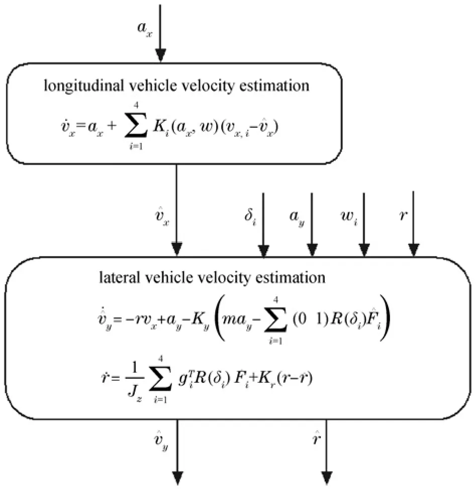
Fig.3. Example of a modular scheme for vehicle dynamic state estimation.
Regardless of what scheme is adopted,the excitation conditions should be considered because road information is always regarded as the unknown input of vehicle dynamics.Moreover,the longer the sufficient excitation is,the more accurate the vehicle dynamic states obtained[32].This is a valuable problem that requires in-depth consideration during vehicle state estimation.
III.SENSOR CONFIGURATION SCHEMES FOR VEHICLE DYNAMIC STATE ESTIMATION
The sensor con figuration discussed here is used to estimate only the vehicle dynamic states excluding the validation of the estimation schemes.The estimation precision and the cost of sensor equipment should be synthesized to determine the specific sensor con figuration scheme.It is better to adopt a relatively low-cost sensor to reduce the cost of mass-production vehicles on the premise that the estimation precision is not influenced.Moreover,the choice of estimation method and vehicle model strongly depends on the sensor con figuration scheme.The sensor con figuration scheme varies on the basis of the vehicle dynamic states to be estimated.Therefore,the sensor con figuration scheme should consider the dynamic state to be estimated,the estimation algorithm and the price of the sensor for mass-production vehicles.According to the discussions above,sensor con figuration schemes for typical vehicle dynamic states are investigated in this section.
1)Sensor Con figuration of Vehicle Velocity Estimation:Vehicle velocity estimation,which includes longitudinal velocity,lateral velocity,and vertical velocity estimation,is a popular topic in vehicle active safety control and ADAS.Several sensor equipment schemes are employed to predict this information,and Table II lists the main vehicle velocity estimation schemes from the perspective of the sensor con figuration,vehicle model and estimation strategy.
A vehicle equipped with ESP could obtain measurements of the lateral accelerationay,yaw rater,steering wheel angleδand wheel angular velocityωi.Additionally,the longitudinal accelerationaxcould be obtained with a separate inertial measurement unit(IMU)[30].This con figuration corresponds to the first scheme in Table II,which is the most common sensor con figuration scheme in vehicle velocity estimation[30],[33].The longitudinal and lateral vehicle velocities can be obtained using different estimation approaches[30],[32]-[39].Considering onboard sensors equipped on commercial vehicles,this con figuration is the most promising way to perform vehicle velocity estimation for mass-production vehicles.Based on the sensor con figuration scheme mentioned above,the wheel steering angleδ,wheel rotational speedωiand yaw raterare used as the measurements,and a reduced nonlinear observer(RNLO)estimation scheme is proposed in[40].This scheme is also suitable for mass-production vehicles.In addition,considering the unbridgeable problem in vehicle velocity estimation of the unknown tire-road friction coefficient,longitudinal velocity is used instead of longitudinal acceleration because the accelerometer cannot normally be placed in the exact CoG due to design restrictions.Then,dual extended Kalman filter(DEKF)and nonlinear unknown input observer(NUIO)strategies are proposed in[41],[42].Additionally,the steering wheel angle and yaw rate are employed as measurements to estimate lateral velocity in[43].Fewer sensors are used in this estimation scheme;however,the estimation precision must be improved.
In contrast to the sensor con figuration schemes discussed above,inexpensive 6D IMU is employed in[44]to obtain more measurement information.This con figuration can obtain sufficient measurements to implement more complex estimation schemes.The longitudinal velocity estimation for electrical vehicles is discussed in[45].In addition to the conventional measurements,the wheel torque provided by the electric motor can be measured to detect excessive wheel slip and improve the accuracy of the estimation.In addition to the measurements in[45],lateral acceleration is measured in[46],and the longitudinal and lateral vehicle velocities can be estimated simultaneously using the modular estimation scheme to obtain acceptable experimental results.
2)Sensor Con figuration of Sideslip Angle Estimation:Realtime information of the sideslip angle is useful in many active vehicle safety applications,including yaw stability control[47],rollover prevention[48],and lane departure avoidance[49].Sideslip angle estimation has become a hot topic of discussion because measuring the sideslip angle with sensors is expensive for ordinary automotive that applications with 2-antenna GPS systems and optical sensors.Sideslip angle estimation sometimes depends on indirect estimation,which can be evaluated using the estimated longitudinal and lateral vehicle velocities[28].Therefore,the potential sensor con figuration schemes are abundant.Accordingly,Table III lists the sensor con figuration schemes,vehicle models and estimation methods for the sideslip angle estimation problem.
Table III shows how the wheel steering angle and yaw rate are measured to estimate the sideslip angle in[50],[51].It also considers three sets of sensors to observe the impact on the observer results.By contrast,the steering wheel angle and lateral acceleration are taken as measurements,and the sideslip angle estimation problem is discussed using moving horizon estimation(MHE)in[52].Based on the measurements in[52],taking the lateral acceleration as an additional measurement,three estimation schemes for vehicle sideslip angle estimation are compared and model simplification and observability analysis are conducted in[53].Additionally,using the wheel rotational speeds as additional measurements,the UKF,artificial neural network(ANN)and NLO are employed to estimate the sideslip angle in[54],[55].Compared with the sensor con figuration scheme in[56],[57],the wheel rotational speed is neglected in[28].This estimation scheme reduces the computational complexity compared with the EKF,which makes the observer suitable for implementation in embedded hardware.
Although the sensor con figuration scheme discussed above could obtain the sideslip angle,the most widely applied sensor con figuration on actual standard cars that is used to estimate the sideslip angle is described in[58]-[60],[36],[61],[30],[34].It is also the most promising estimation scheme to implement on the mass-production vehicles.Furthermore,several other sensor con figuration schemes have been derived,for example,the longitudinal vehicle velocity replaces the wheel rotational speed in[62]-[64],and the longitudinal vehicle velocity is substituted for the wheel rotational speed and longitudinal acceleration in[65],[66].All the measurements can be used to obtain acceptable sideslip angle estimation results.
In contrast to the popular sensor con figuration schemes above,the suspension deflection and roll rate are measured in[67],[68].The sensor con figuration schemes can determine the sideslip angle using different estimation schemes,including a high-gain observer(HGO)and EKF.Moreover,the wheel rotational speed,braking torque,longitudinal velocity and normal force are measured in[69]to estimate the sideslip angle.The GPS tracking angleφGPSand GPS ground velocityvGPSare measured in[70],in addition to the measurements in[60],which adopts an adaptive hybrid fusion strategy to predict the vehicle sideslip angle for a wide range of driving maneuvers.GPS is also employed in[71]for sideslip angle estimation.With the rapid development of sensor technology,low-cost GPS has become available to mass-production vehicles;accordingly,this sensor con figuration scheme would be useful in the future.

TABLE IISENSOR CONFIGURATION,VEHICLE MODEL,AND ESTIMATION METHOD FOR VEHICLE VELOCITY ESTIMATION

TABLE IIISENSOR CONFIGURATION,VEHICLE MODEL,AND ESTIMATION METHOD FOR SIDESLIP ANGLE ESTIMATION
3)Sensor Con figuration of Yaw Rate Estimation:The yaw rate can be measured directly by gyroscope.However,this measurement is not sufficient to satisfy the demands of vehicle active safety control because old-fashioned mechanical gyroscopes are characterized by large size,frangibility,easily powering down and temperature drift error.Therefore,yaw rate estimation has been discussed in recent years.In addition,it is necessary to estimate yaw rate for gyroscope fault diagnosis from another perspective.Based on an extensive survey of the published literature,Table IV lists the representative estimation strategies and sensor con figuration schemes for yaw rate estimation.
According to the sensor con figuration schemes in Table IV,the most widely discussed sensor con figuration scheme for yaw rate is similar to those of the sideslip angle and vehicle velocities in[28]-[30],[34]-[36],[58],[59],[72],[73].Based on sensor con figuration schemes,the longitudinal acceleration is omitted in[54],[55],and NLO and UKF are proposed,respectively,to estimate the yaw rate and vehicle velocities.In addition,based on the measurement of the steering wheel angle,longitudinal vehicle velocity,yaw rate and lateral acceleration,a simple and accurate approach is introduced in[74]based on direct identification from filter data.These sensor con figuration schemes are conventional ones for yaw rate estimation.
In contrast to the sensor con figuration schemes discussed above,GPS is used in[71].The GPS signal is also used in[70]for yaw rate and sideslip angle estimation.Aiming to estimate the yaw rate and sideslip angle,a novel estimation method is presented in terms of the recognition of vehicle dynamic parameters based on the corning kinetics and corning geometry of vehicles using the velocity of the wheels in[75].Moreover,the suspension deflection,longitudinal velocity and longitudinal acceleration are measured in[76]to comprehensively discuss the yaw rate and velocity estimation.In addition to the sensor con figuration schemes above,there are some con figuration schemes where the yaw rate is considered as a by-product of the estimation of other dynamic states[52].As the literature survey shows,yaw rate estimation is rarely discussed alone,it is often obtained as the by-product of vehicle velocity and sideslip angle estimation.Furthermore,the sensor con figuration schemes for other vehicle dynamic state estimation problems can be explored for yaw rate estimation.
4)Sensor Con figuration for Roll Angle Estimation:The roll angle is indispensable information for active rollover prevention systems to prevent vehicle rollover,which accounts for a significant percentage of highway traffic fatalities[77].Additionally,the roll angle estimate is used to compensate the gravity component when measuring the lateral acceleration due to vehicle roll or the road bank angle.Due to the consideration of roll motion,the sensors used for other vehicle dynamic state measurements are relatively more abundant than those used for the independent estimation of sideslip angle,vehicle velocities,and tire-road forces.In order to survey the representative sensor con figuration,vehicle model,and estimation strategies,Table V lists the main estimation schemes for roll angle estimation.
From Table V,it can be observed that the steering wheel angle,yaw rate,lateral acceleration,lateral tire-road force and in-wheel motor torque are used as measurements,and the Kalman filter(KF)is adopted to discuss the roll angle estimation in[51].Additionally,the sideslip angle is estimated using the yaw rate and steering angle measurements.To estimate the roll and pitch angle,a low-price six-dimensional IMU is employed in[78].The relations among the yaw rate,pitch rate,roll rate,and pitch angle are simplified,and observers are constructed using modern linear control theory.Moreover,based on the sensor con figuration in[78],the measurements of wheel speed sensors and steering-wheel angle are exploited in[79].A novel scheme for reference angle selection that depends on the cornering-stiffness adaptation is adopted to observe the angles on the basis of the combination of velocity kinematics and pseudo integration of the angle kinematics.Additionally,a roll rate sensor and the sensors that are readily available in vehicles equipped with ESP systems are used in[80]for roll angle estimation.Similar to the sensor con figuration scheme above,the longitudinal velocity is viewed as varying slowly in[81],and the KF is proposed to estimate the roll angle.Moveover,the UIO is adopted to estimate the roll angle using the roll rate and lateral acceleration measurements in[82].The height of the CoG can also be predicted,with a low-frequency tilt-angle sensor and a gyroscope used as additional sensor.In addition to the sensor con figuration schemes above,measurements obtained from ESP systems are explored to estimate the roll angle in[61],[83].Moreover,the longitudinal accelerations and yaw rate are omitted in[84],and the roll angle can be estimated using DEKF and state index switching strategies.
According to the sensor con figuration schemes discussed above,roll angle estimation is mainly divided into two aspects.One is considering the roll dynamics,which requires more sensors.The estimation results are validated by experiments,and effective results are obtained on banked roads.The other is the the roll angle conceived as the unknown input of the observer,where the roll angle is estimated as the unknown parameter.The estimation results are also validated using experiments under some typical operating conditions.In the sensor con figuration schemes discussed above,the characteristics of the sensor,such as noise,bias and drift,and the various road conditions affect the measurement accuracy.Since the measurement precision of a sensor is directly related to its estimation performance,the compensation of the sensor signal should be considered.Filtering techniques are introduced in[85],[86]for accelerometers and gyroscopes.Due to space limitations,the compensation of the sensor signal is not discussed in detail here.
IV.VEHICLE MODELS FOR VEHICLE DYNAMIC STATE ESTIMATION
Vehicle dynamic state estimation can be categorized into kinematics-based models and dynamics-oriented models.In this section,the physical model used in vehicle state estimation is introduced.
A.Kinematics-based Models
The kinematics-based method is concerned with the motion of objects without reference to forces and torques.Due to the various views of kinematics modeling in vehicle systems,there is a large quantity of kinematics-based models.The representative kinematics-based model considering the relationships among lateral acceleration,yaw rate and the variation of lateral acceleration in[87]is presented as follows:

In addition,considering the relationship among yaw rate,lateral acceleration,longitudinal velocity,road bank angle and sideslip angle in[88],the lateral acceleration is expressed as

Accordingly,the sideslip angle estimation can also be obtained by integrating(2)

Vehicle dynamic state estimation using kinematics-based models mainly involves numerical integration from sensors or establishing a kinematic estimator according to the con figuration.However,noise accumulates when integrating over a long period of time,resulting in large estimation error.Therefore,kinematics-based methods have become less common in the recent years.
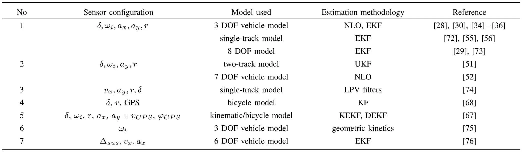
TABLE IVSENSOR USED FOR YAW RATE ESTIMATION
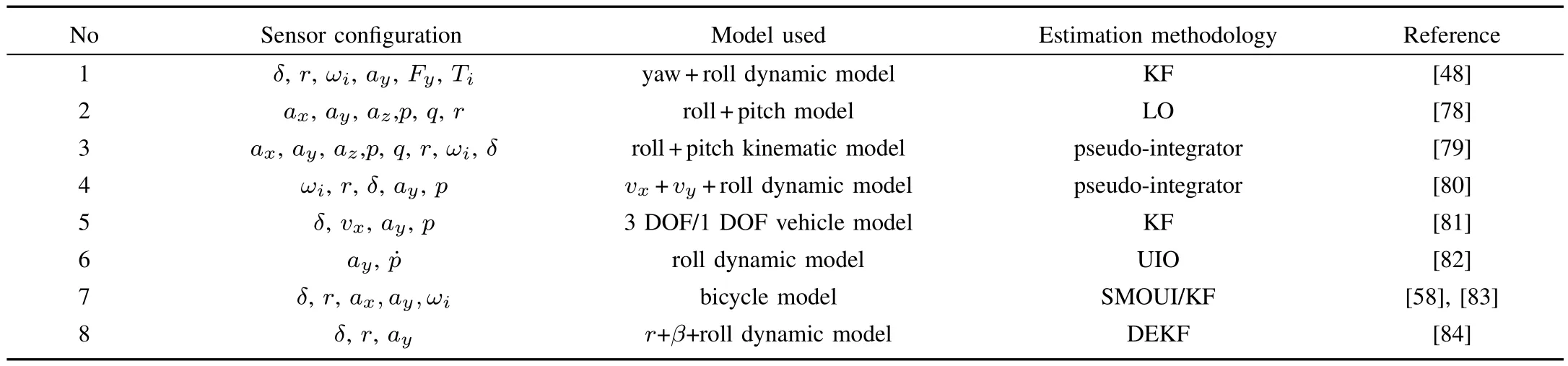
TABLE VSENSOR AND ESTIMATION STRATEGIES USED FOR ROLL ANGLE ESTIMATION
B.Dynamics-oriented Models
There are numerous degrees of freedom associated with vehicle dynamics.Vehicle state estimation should be concentrated on dynamics related to the estimation of the states.Moreover,each type of vehicle dynamics model is based on suitable assumptions.
1)Longitudinal Motion Model:The longitudinal motion model concentrates on the force or torque in the longitudinal direction while ignoring the lateral dynamics.The longitudinal velocity and the wheel rotational speed are considered in longitudinal motion when the friction coefficient or longitudinal velocity estimation is discussed.According to the force balance in the longitudinal direction and the torque balance of wheel rotation,the dynamic model is given as follows:

The dynamic behavior of the system is hidden in the expression ofFx.The most general expression ofFxis complex as it depends on a large number of features of the road,tire and suspension.In general,it can be expressed as a function of the normal tire-forceFzand tire-road friction coefficientµ,which is a function of the longitudinal slipSx,wheel side-slip angle,and a set of parametersνr[35].

2)Single-track Model:The single-track model in Fig.4 is also called the bicycle model or 2 DOF vehicle model.It is currently used to describe lateral vehicle dynamic behavior.In this model,vertical motion,roll and pitch are ignored,and longitudinal velocity is assumed to be constant.There are two forms of the bicycle model that consider different states variables.In one form,the vehicle’s handling dynamics in the yaw plane are represented by the states of the sideslip angleβand the yaw rateras follows
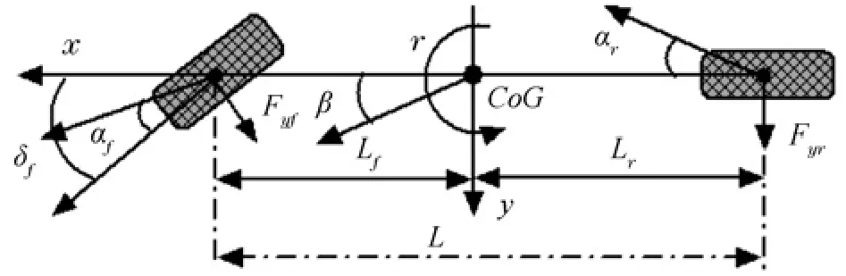
Fig.4.2 DOF vehicle dynamic model.

The lateral tire-road forcesFyfandFyr,considered to be a function of the lateral sideslip angle,can be obtained by various types of tire model.For example,the linear tire model is used to describe the tire-road force and the lateral sideslip angle is computed based on assumption[89]
The most famous bicycle model was presented in[89].In other cases,the lateral vehicle velocityvyand yaw raterare considered as dynamic states,and the 2 DOF vehicle model can be described as follows

In fact,these two vehicle models described in(6)and(8)are equivalent on the condition that the longitudinal velocity is assumed to be constant.
3)3 DOF Vehicle Model:The 2 DOF vehicle model introduced above only considers the lateral dynamics.If the longitudinal dynamics are also considered,as shown in Fig.1,the 3 DOF vehicle model can be obtained in the form of the longitudinal velocity,lateral velocity and yaw rate,which are described as follows[40]:
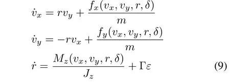
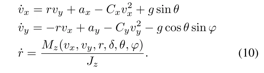
wherefx(vx,vy,r,δ),fy(vx,vy,r,δ)andMz(vx,vy,r,δ)are computed according to the tire-road forces in[40].The 3 DOF vehicle model can be simplified on the condition that the longitudinal and lateral acceleration can be measured[30].Moreover,considering the presence of nonzero inclination,road bank angles,and air-force resistance,the 3 DOF vehicle model above can be written as follows:
4)7 DOF Vehicle Model:Based on the 3 DOF vehicle model described in(10),the 7 DOF vehicle model is introduced[55]to consider the four wheel rotational speeds as additional dynamic states.
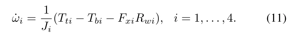
The wheel rotational speed can be computed based on the above description.The wheel rotational speed can be transformed into longitudinal velocityvx,assuming zero slip,and the transformed expression for velocity from wheeliis

The computed longitudinal velocity in(12)is often used as the correction for the longitudinal velocity estimation[30].
5)8 DOF Vehicle Model:When roll motion is added to the 7 DOF vehicle model above,the 8 DOF vehicle model is obtained as follows:

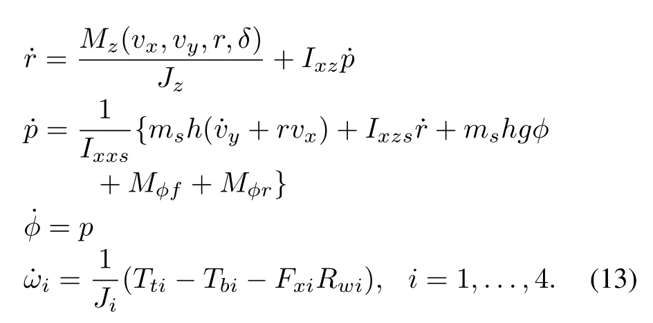
The symbols in this vehicle model are described in[29].The 8 DOF vehicle model is discussed extensively in vehicle dynamics,and it is often proposed in vehicle state estimation and vehicle rollover prevention.
In addition to the conventional vehicle models listed above,there are also 5 DOF and 6 DOF vehicle models,which are extracted from the discussed vehicle dynamic states.Moreover,by considering the steering dynamics and suspension movement in the vertical direction,a 14 DOF vehicle model or other degrees of freedom vehicle models could be obtained.
V.REPRESENTATIVE DYNAMICS-ORIENTED VEHICLE DYNAMIC STATE ESTIMATION METHODS
From the perspective of the vehicle model introduced above,the vehicle dynamic state estimation schemes can be divided into kinematics-based methods and dynamics-oriented approaches.Therefore,representative dynamics-oriented vehicle state estimation methods are discussed in this section.
A.Kalman Filter
The Kalman filter(KF),also known as linear quadratic estimation(LQE),is an algorithm that uses a series of measurements observed over time and containing noise and other inaccuracies to produce estimates of unknown variables.KF is a conventional approach that operates recursively on streams of noisy input to produce a statistically optimal estimate of vehicle dynamic states.The filter is composed of a two-step process,namely,a prediction step and an updating step.
In the prediction step,KF estimates the current states,along with their uncertainties.After the outcome of the next measurement is observed,the estimates are updated using a weighted average.Several studies on this topic have been reported.For example,a KF is proposed to estimate roll angle and roll rate based on a 3 DOF vehicle model in[81].A novel method based on AKF is presented for estimating vehicle velocities in[37]by updating the mean and covariance of the noise online.This method has high adaptability and can obtain high precision when an appropriate logic threshold is selected.Through the above research,it can be concluded that the KF is suitable for vehicle dynamic state estimation under normal driving conditions.However,vehicle driving conditions are extremely complex.When a vehicle is operated under critical conditions,the vehicle exhibits strong nonlinearity.In this situation,the deviation between the vehicle dynamics described by a linear vehicle model and the actual vehicle system is large.Accordingly,the performance of the KF in this situation is greatly reduced,and in some cases,the divergence phenomenon appears.In such situation,EKF is adopted to estimate the vehicle dynamic states using a more precise nonlinear vehicle model.
EKF estimates vehicle dynamic states using a nonlinear vehicle model.It linearizes an estimation of the current mean and covariance using first-order Taylor expansion.Then,a linear KF is applied.In[36],[50],vehicle velocities,yaw rate and road attributes are estimated using the EKF method,and the estimated vehicle longitudinal tire force and tire-road friction coefficient are obtained.The estimated road gradient and vehicle sideslip angle are also obtained based on these results.In addition,the vehicle sideslip angle and tire cornering stiffness are effectively estimated in[72]based on the tire-road force minimum mean square error estimation using EKF.Moreover,EKF is suitable for conditions with varied vehicle parameters.To address the variation of the tire-road friction coefficient and the friction force,the implementation of a model-based vehicle estimator is presented in[41]using a dual extended KF(DEKF).
EKF employs a nonlinear vehicle dynamics model that with highly precise vehicle descriptions.Moreover,recursive processing is adopted,which simpli fies the calculation and is easy to implement.As a result,a high-precision estimation is obtained.Therefore,EKF is widely used to discuss vehicle dynamic state estimation issues.However,EKF has its own shortcomings.The EKF parameters must be re-tuned when the adhesion coefficient of the road surface varies[90].Moreover,EKF is suitable for discussing the estimation problem of weak nonlinearity.The performance under highly nonlinear conditions might deteriorate substantially,which is a key issue to be improved for mass-production vehicles.
B.Artificial Intelligence Estimation Method
The artificial intelligence estimation method for vehicle dynamic state estimation is a combination of the conventional estimation method and intelligent approaches.Its generation and development rely on a conventional estimation method.Artificial neural networks and fuzzy logic are the most common intelligent methods.
ANN is a computational model inspired by an animal’s central nervous systems that is capable of machine learning and pattern recognition.Experimental data are applied to an ANN to assess the performance of the sideslip angle in[64].In addition to the above neural networks,a two-level radial basis function(RBF)neural network is proposed in[69]to approximate the unknown part of a system based on the single wheel model,which makes tire force estimation insensitive to the model inaccuracies.The neural network has strong intelligent processing capacities,including self-learning ability,adaptive capacity,and complex relational mapping capabilities.Therefore,it is suitable for nonlinear systems where only input and output information is known.The application of this method has produced good test results,especially in the nonlinear domain of vehicle driving.However,the test data employed to train the ANN should be reflective of various driving conditions.Moreover,the mapping relationships of ANN are strongly dependent on the experimental data,and it is difficult to describe the mechanism of the mapping relationships.In addition,the convergence rate of ANN applied to vehicle dynamic state estimation is relatively slow;accordingly,the numerical stability is sometimes difficult to determine.
Fuzzy logic can be applied to concepts that can be expressed as “partially true”.Although alternative approaches,such as genetic algorithms and neural networks,can perform as well as fuzzy logic in many cases,fuzzy logic can be cast in terms of human operators,whose experience can be included in the design of the estimator.In[63],a fuzzy logic procedure is implemented to identify steady state and transient conditions in sideslip angle estimation.The fuzzy logic approach does not require special assumptions on the input signal,and it possesses a good robustness performance when faced with varying vehicle parameters and noise inputs.Moreover,because the fuzzy-based observer obtains high-frequency responses,perfect estimation accuracy can be achieved.Therefore,fuzzy logic estimation is suitable for state and parameter estimation in nonlinear systems.Moreover,the real-time performance of fuzzy logic satisfies the requirements of vehicle active safety systems.In addition,fuzzy logic can easily integrate engineers’experience.However,fuzzy logic has its own shortcomings.For example,it relies heavily on experience for weight parameter selection,and there are no qualitative rules available for reference.Due to the variety and complexity of vehicle operating conditions,complete fuzzy rules are are often too difficult to establish.Due to the lack of complete fuzzy rules,the requirements of the main control logic cannot be satisfied and the overall vehicle driving conditions cannot be considered.Thus,there are difficulties in engineering applications.
C.Observer-based Method
Vehicle dynamic state estimation can be formulated as an observer design problem if the vehicle dynamics system can be described as a deterministic system.To compensate the influence of modeling error,process noise and unmodeled dynamics,a correction term is determined according to the relationship between the measured output and states to be estimated.A Luenberger observer is often used to estimate the vehicle dynamic states.For example,two kinematics-based Luenberger observers are proposed to estimate vehicle roll and pitch angles using IMU in[78].Moreover,with varied observer gain,the estimated roll or pitch angle is shown to asymptotically converge to the true value.The test results of the observer mentioned above are satisfied in the linear region of vehicle operation,but the accuracy of the observer decreases as the velocity increases because the estimation precision is strongly related to the vehicle model.Therefore,researchers have introduced nonlinear vehicle dynamic models and nonlinear observers to estimate dynamic states.
The nonlinear observer based on the principle of Luenberger observers has been discussed extensively.The vehicle velocity and yaw rate are estimated using a nonlinear observer in[30],[34].The ISS estimation results,for which it is relatively difficult to obtain stable results,can be obtained using this method.In addition,the roll angle is estimated using an observer based on a roll dynamic model in[82].In addition to the consideration of a varying road friction coefficient in[28],[65],the adaptive NLO is discussed for the sideslip angle estimation problem.Moreover,an NLO to estimate vehicle velocity in the presence of varying friction and road bank angle is presented in[33].The performance of the NLO is as good as that of the EKF while having significantly lower computational complexity.The NLO method is flexible,and various observations can be obtained based on different vehicle models.NLO has achieved good test results under both normal and critical conditions.Accordingly,NLO is valuable for further study.In addition,the structure of the nonlinear observer is relatively simple compared with EKF.Moreover,compared with EKF and the optimal estimation method,satisfactory realtime performance is obtained when applied to a real vehicle.However,NLO is fragile under varying parameter conditions.In this situation,the unknown input observer(UIO)is a suitable solution.For example,a nonlinear UIO is designed for vehicle lateral velocity estimation on banked roads in[42],where it is concluded that the error dynamics for a nonlinear UIO have the same structure as those of a nonlinear observer without unknown inputs.
In addition to NLO,SMO is often used to estimate vehicle dynamic states.In order to estimate sideslip angle,an SMO is proposed in[50],which demonstrates the effectiveness of using both a validated simulator and experimental data obtained with a laboratory car.Additionally,a robust method for estimating the lateral velocity with a simple structure that contains a sliding mode term that is robust against output noise,parameter variation and sustained disturbances is presented in[91].The given nonlinear model of the vehicle is then represented by an uncertain T-S fuzzy model when the road adhesion conditions change.The stability conditions of such observers are expressed in terms of linear matrix inequalities(LMI).SMO is characterized by a small number of calculations and a simple design procedure.Moreover,it can reconstruct the state by forcing the system into the sliding mode surface.SMO also inherits the suppression of parameter uncertainty in the model error by varying the structure control.However,the choice of filtering time must be simultaneously as small as possible and sufficiently large to suppress the high-frequency noise of the system.Therefore,the selection of the filter time is difficult.Simultaneously,as with the nonlinear observer,the choice of observer gain requires a large number of repeated regulations to satisfy the accuracy requirements of the vehicle active safety system.
D.Optimization-based Estimation Method
In recent years,moving horizon estimation(MHE),based on the same optimization principle as model predictive control(MPC)[92]-[94],has been applied to the vehicle dynamic state estimation problem.For example,an MHE method to predict vehicle yaw rate and sideslip angle based on the linear vehicle dynamic model is proposed in[52].MHE can explicitly express and optimize the state constraints in the estimation process by taking full advantage of the given information of states and disturbance.Accordingly,the rationality and accuracy of the estimation are improved.The above MHE methods extensively address the vehicle dynamic state estimation problem;however,the estimation schemes have not been verified experimentally because MHE requires substantial calculation,which affects the real-time performance of vehicle dynamic state estimation.This is the main shortcoming of MHE that affects its application in mass-production vehicles and should be improved in future estimation research.
VI.FURTHER RESEARCH CONCERNS AND PERSPECTIVES
Vehicle dynamic state estimation has been greatly promoted from various aspects in recent years,and there have been many successful applications in mass-production vehicles.However,some interesting and promising issues in vehicle dynamic state estimation require further consideration.
1)The range of vehicle dynamic state estimation must be extended towards automated and connected vehicles.
In recent years,intelligent transportation systems,autonomous driving,connected vehicles and cyber-physical systems[4],[95],[96]have been rapidly developed,extending the requirements of vehicle dynamic state estimation.Connected vehicles require information about tire-road interactions,dynamic states and the positions of other vehicles to make decisions.The distance and relative speed of other vehicles must be predicted to determine the next position and dynamic state.In addition,human driver information is functionally required to initiate an automated driving system and which may or may not do so even when driving conditions are within the capability of the system.Therefore,vehicle dynamic state estimation must be extended to obtain that information.
2)The serious coupling problem encountered by vehicle dynamic state estimation.
Due to signal exchange between various physical components,the dynamic state variables are strongly coupled,placing a huge burden on the design of the dynamic state observer.Additionally,onboard sensors are scattered at different positions on the vehicle,and the measured signals belong to various subsystems,making vehicle dynamic state estimation extremely challenging.Accordingly,additional state and parameters information is often required in advance to estimate a single vehicle dynamic state.Considering the above situation,the overall structure of vehicle dynamic state estimation should be analyzed to carefully determine the various requirements of each module.Based on the existing estimation structures,adopting a distributed modular estimation strategy and designing the estimator or observer according to the different performance requirements and dynamic characteristics of different modules are effective ways to solve the serious coupling problem in vehicle dynamic state estimation.
3)The issue of vehicle dynamic state estimation with unknown inputs.
Tire-road interactions,such as the road inclination angle,tire-road friction coefficient and road slope angle,are unknown input information of vehicle dynamics systems.The road information should be obtained first to predict vehicle dynamic states,which results in an unknown input estimation problem.Unknown road information has mostly been ignored by the existing estimation schemes by assuming that the information is already known.With the rapid development of estimation theory,the superiority of the extended state observer,unknown input observer and adaptive observer[29],[97],[32]has gradually appeared to solve this problem.These estimation strategies will likely become suitable methods to solve the vehicle dynamic state estimation problem with unknown road information.
4)The stability and robustness of vehicle dynamic state estimation.
When a modular estimation scheme is employed,the stability of each module can be addressed using Lyapunov theory.However,the overall stability of the modular observer must be analyzed,which is a challenging problem.Moreover,modeling errors exist,and the parameters will vary to some extent when the vehicle is operating under different road conditions.Therefore,uncertainty is present in the vehicle model.Additionally,varied road conditions and lateral wind constitute external vehicle disturbances.Therefore,it is valuable to discuss how the vehicle dynamic state observer addresses the uncertainty and external disturbances in vehicle model.The wide range of application of ISS theory[30]makes it an effective measure to discuss the overall stability and robustness of the modular estimation scheme.
5)The real-time issue of vehicle dynamic state estimation.
The states of vehicle systems change rapidly during vehicle operation,and the control cycle of the electronic control unit is approximately 20 ms[33],which places specific real-time requirements on the vehicle dynamic state estimation algorithm.Furthermore,the miniaturization of modern cars requires the vehicle dynamic state estimation algorithm to be implemented on chips.Due to the above problems,it is valuable to consider vehicle dynamic state estimation methods that satisfy the miniaturization and real-time requirements.Considering the small amount of calculation and fast calculating speed,a nonlinear observer is a practical way to solve the miniaturization and real-time problems in vehicle dynamic state estimation.Moreover,with the progress of hardware technology on Field-Programmable Gate Array(FPGA)[35],a hardware implementation that employs Field-Programmable Gate Array/System-on-a-Programmable-Chip(FPGA/SoPC)to solve the miniaturization and real-time problems is also feasible.
[1]F.Y.Wang and P.K.Wang,“Intelligent systems and technology for integrative and predictive medicine:An ACP approach,”ACM Trans.Intell.Syst.Technol.,vol.4,no.2,pp.Article No.32,Mar.2013.
[2]T.Qu,H.Chen,D.P.Cao,H.Y.Guo,and B.Z.Gao,“Switchingbased stochastic model predictive control approach for modeling driver steering skill,”IEEE Trans.Intell.Transp.Syst.,vol.16,no.1,pp.365-375,Feb.2015.
[3]F.Y.Wang,“Parallel control and management for intelligent transportation systems:Concepts,architectures,and applications,”IEEE Trans.Intell.Transp.Syst.,vol.11,no.3,pp.630-638,Sep.2010.
[4]T.X.Bai,S.Wang,Z.Shen,D.P.Cao,N.N.Zheng,and F.Y.Wang,“Parallel robotics and parallel unmanned systems:Framework,structure,process,platform and applications,”Acta Automat.Sin.,vol.43,no.2,pp.161-175,Feb.2017.
[5]F.Y.Wang,J.Zhang,Q.L.Wei,X.H.Zheng,and L.Li,“PDP:Parallel dynamic programming,”IEEE/CAAJ.Automat.Sin.,vol.4,no.1,pp.1-5,Jan.2017.
[6]O.Ghahabi and J.Hernando,“Deep learning backend for single and multisession i-vector speaker recognition,”IEEE/ACM Trans.Audio,Speech,Lang.Process.,vol.25,no.4,pp.807-817,Apr.2017.
[7]G.Xiong,F.H.Zhu,X.W.Liu,X.S.Dong,W.L.Huang,S.H.Chen,and K.Zhao,“Cyber-physical-social system in intelligent transportation,”IEEE/CAAJ.Automat.Sin.,vol.2,no.3,pp.320-333,Jul.2015.
[8]L.Li and F.Y.Wang,Advanced Motion Control and Sensing for
Intelligent Vehicles.Berlin Heidelberg,German:Springer-Verlag,2010.
[9]L.Li,D.Wen,N.N.Zheng,and L.C.Shen,“Cognitive cars:A new frontier for ADAS research,”IEEE Trans.Intell.Transp.Syst.,vol.13,no.1,pp.395-407,Mar.2012.
[10]H.H.Jing,Z.Y.Liu,and H.Chen,“A switched control strategy for antilock braking system with on/off valves,”IEEE Trans.Veh.Technol.,vol.60,no.4,pp.1470-1484,May 2011.
[11]W.Zhang and X.X.Guo,“An ABS control strategy for commercial vehicle,”IEEE/ASME Trans.Mechatron.,vol.20,no.1,pp.384-392,Feb.2015.
[12]P.Shakouri and A.Ordys,“Nonlinear model predictive control approach in design of adaptive cruise control with automated switching to cruise control,”Control Eng.Pract.,vol.26,pp.160-177,May 2014.
[13]M.Amodeo,A.Ferrara,R.Terzaghi,and C.Vecchio,“Wheel slip control via second-order sliding-mode generation,”IEEE Trans.Intell.Transp.Syst.,vol.11,no.1,pp.122-131,Mar.2010.
[14]K.J.Waldron and M.E.Abdallah,“An optimal traction control scheme for off-road operation of robotic vehicles,”IEEE/ASME Trans.Mechatron.,vol.12,no.2,pp.126-133,Apr.2007.
[15]W.Cho,J.Choi,C.Kim,S.Choi,and K.Yi,“Uni fied chassis control
for the improvement of agility,maneuverability,and lateral stability,”IEEE Trans.Veh.Technol.,vol.61,no.3,pp.1008-1020,Mar.2012.
[16]A.Goodarzi and E.Esmailzadeh,“Design of a VDC system for allwheel independent drive vehicles,”IEEE/ASME Trans.Mechatron.,vol.12,no.6,pp.632-639,Dec.2007.
[17]K.Nam,H.Fujimoto,and Y.Hori,“Advanced motion control of electric vehicles based on robust lateral tire force control via active front steering,”IEEE/ASME Trans.Mechatron.,vol.19,no.1,pp.289-299,Feb.2014.
[18]H.Chen and K.H.Guo,“ConstrainedH∞control of active suspensions:An LMI approach,”IEEE Trans.Control Syst.Technol.,vol.13,no.3,pp.412-421,May 2005.
[19]W.C.Sun,H.J.Gao,and O.Kaynak,“Adaptive Backstepping control for active suspension systems with hard constraints,”IEEE/ASME Trans.Mechatron.,vol.18,no.3,pp.1072-1079,Jun.2013.
[20]M.E.Hoque,M.Takasaki,Y.Ishino,and T.Mizuno,“Development of a three-axis active vibration isolator using zero-power control,”IEEE/ASME Trans.Mechatron.,vol.11,no.4,pp.462-470,Aug.2006.
[21]C.M.Farmer,“New evidence concerning fatal crashes of passenger vehicles before and after adding antilock braking systems,”Accid.Anal.Prev.,vol.33,no.3,pp.361-369,May 2001.
[22]K.T.Leung,J.F.Whidborne,D.Purdy,and A.Dunoyer,“A review of ground vehicle dynamic state estimations utilising GPS/INS,”Veh.Syst.Dyn.,vol.49,no.1-2,pp.29-58,Jan.2011.
[23]H.F.Grip,L.Imsland,T.A.Johansen,T.I.Fossen,J.C.Kalkkuhl,and A.Suissa,“Nonlinear vehicle velocity observer with road-tire friction adaptation,”inProc.45th IEEE Conf.Decision and Control,San Diego,CA,USA,2006,pp.3603-3608.
[24]J.Ryu,State and Parameter Estimation for Vehicle Dynamics Control Using GPS.Palo Alto,CA,USA:Stanford University,2004.
[25]P.Freeman,R.Pandita,N.Srivastava,and G.Balas,“Model-based and data-driven fault detection performance for a small UAV,”IEEE/ASME Trans.Mechatron.,vol.18,no.4,pp.1300-1309,Aug.2013.
[26]D.Rubinstein and R.Hitron,“A detailed multi-body model for dynamic simulation of off-road tracked vehicles,”J.Terramechan.,vol.41,no.2-3,pp.163-173,Apr.-Jul.2004.
[27]R.Rajamani,Vehicle Dynamics and Control.New York,USA:Springer-Verlag,2006.
[28]H.F.Grip,L.Imsland,T.A.Johansen,J.C.Kalkkuhl,and A.Suissa,“Vehicle sideslip estimation:Design,implementation,and experimental validation,”IEEE Control Syst.Mag.,vol.29,no.5,pp.36-52,Jan.2009.
[29]L.R.Ray,“Nonlinear tire force estimation and road friction identification:Simulation and experiments,”Automatica,vol.33,no.10,pp.1819-1833,Oct.1997.
[30]L.Imsland,T.A.Johansen,T.I.Fossen,H.F.Grip,J.C.Kalkkuhl,and A.Suissa,“Vehicle velocity estimation using nonlinear observers,”Automatica,vol.42,no.12,pp.2091-2103,Dec.2006.
[31]E.Hashemia,S.Khosravani,A.Khajepour,A.Kasaiezadeh,S.K.Chen,and B.Litkouhi,“Longitudinal vehicle state estimation using nonlinear and parameter-varying observers,”Mechatronics,vol.43,pp.28-39,May 2017.
[32]H.F.Grip,L.Imsland,T.A.Johansen,T.I.Fossen,J.C.Kalkkuhl,and A.Suissa,“Nonlinear vehicle side-slip estimation with friction adaptation,”Automatica,vol.44,no.3,pp.611-622,Mar.2008.
[33]L.Imsland,H.F.Grip,T.A.Johansen,T.I.Fossen,J.C.Kalkkuhl,and A.Suissa,“Nonlinear observer for vehicle velocity with friction and road bank angle adaptation-validation and comparison with an extended Kalman filter,”inProc.Society of Automotive Engineers(SAE),Michigan,USA,2007.
[34]L.H.Zhao,Z.Y.Liu,and H.Chen,“Design of a nonlinear observer for vehicle velocity estimation and experiments,”IEEE Trans.Control Syst.Technol.,vol.19,no.3,pp.664-672,May 2011.
[35]H.Y.Guo,H.Chen,F.Xu,F.Wang,and G.L.Lu,“Implementation of EKF for vehicle velocities estimation on FPGA,”IEEE Trans.Ind.Electron.,vol.60,no.9,pp.3823-3835,Sep.2013.
[36]A.Katriniok and D.Abel,“Adaptive EKF-based vehicle state estimation with online assessment of local observability,”IEEE Trans.Control Syst.Technol.,vol.24,no.4,pp.1368-1381,Jul.2016.
[37]H.Lee,“Reliability indexed sensor fusion for vehicle longitudinal and lateral velocity estimation,”Int.J.Veh.Des.,vol.33,no.4,pp.351-364,Dec.2003.
[38]J.Kim,“Effect of vehicle model on the estimation of lateral vehicle dynamics,”Int.J.Automot.Technol.,vol.11,no.3,pp.331-337,Jun.2010.
[39]M.Basset,C.Zimmer,and G.L.Gissinger,“Fuzzy approach to the real time longitudinal velocity estimation of a FWD car in critical situations,”Veh.Syst.Dyn.,vol.27,no.5-6,pp.477-489,Nov.1997.
[40]H.Y.Guo,H.Chen,D.P.Cao,and W.W.Jin,“Design of a reducedorder non-linear observer for vehicle velocities estimation,”IET Control Theory Appl.,vol.7,no.17,pp.2056-2068,Nov.2013.
[41]T.A.Wenzel,K.J.Burnham,M.V.Blundell,and R.A.Williams,“Dual extended Kalman filter for vehicle state and parameter estimation,”Veh.Syst.Dyn.,vol.44,no.2,pp.153-171,Feb.2006.
[42]L.Imsland,T.A.Johansen,H.F.Grip,and T.I.Fossen,“On non-linear unknown input observers-applied to lateral vehicle velocity estimation on banked roads,”Int.J.Control,vol.80,no.11,pp.1741-1750,Nov.2007.
[43]A.Y.Ungoren,H.Peng,and H.E.Tseng,“A study on lateral speed estimation methods,”Int.J.Veh.Auton.Syst.,vol.2,no.1-2,pp.126-144,Jul.2004.
[44]J.J.Oh and S.B.Choi,“Vehicle velocity observer design using 6-D IMU and multiple-observer approach,”IEEE Trans.Intell.Transp.Syst.,vol.13,no.4,pp.1865-1879,Dec.2012.
[45]M.Klomp,Y.L.Gao,and F.Bruzelius,“Longitudinal velocity and road slope estimation in hybrid electric vehicles employing early detection of excessive wheel slip,”Veh.Syst.Dyn.,vol.52,no.S1,pp.172-188,May 2014.
[46]E.Hashemia,M.Pirani,A.Khajepour,A.Kasaiezadeh,S.K.Chen,and B.Litkouhi,“Corner-based estimation of tire forces and vehicle velocities robust to road conditions,”Control Eng.Pract.,vol.61,pp.28-40,Apr.2017.
[47]Y.Suzuki and M.Takeda,“An overview on vehicle lateral dynamics and yaw stability control systems,”J.Adv.Veh.Eng.,vol.2,no.4,pp.182-190,2016.
[48]L.Li,Y.S.Lu,R.R.Wang,and J.Chen,“A three-dimensional dynamics control framework of vehicle lateral stability and rollover prevention via active braking with MPC,”IEEE Trans.Ind.Electron.,vol.64,no.4,pp.3389-3401,Apr.2017.
[49]S.Sternlund,J.Strandroth,M.Rizzi,A.Lie,and C.Tingvall,“The effectiveness of lane departure warning systems-a reduction in realworld passenger car injury crashes,”Traf fic Inj.Prev.,vol.18,no.2,pp.225-229,Feb.2016.
[50]J.Ste´phant,A.Charara,and D.Meizel,“Virtual sensor:Application to vehicle sideslip angle and transversal forces,”IEEE Trans.Ind.Electron.,vol.51,no.2,pp.278-289,Apr.2004.
[51]K.Nam,S.Oh,H.Fujimoto,and Y.Hori,“Estimation of sideslip and roll angles of electric vehicles using lateral tire force sensors through RLS and Kalman filter approaches,”IEEE Trans.Ind.Electron.,vol.60,no.3,pp.988-1000,Mar.2013.
[52]H.Y.Zhao and H.Chen,“Estimation of vehicle yaw rate and side slip angle using moving horizon strategy,”inProc.6th World Congr.Control and Automation,Dalian,China,2006,pp.1828-1832.
[53]M.Gadola,D.Chindamo,M.Romano,and F.Padula,“Development and validation of a Kalman filter-based model for vehicle slip angle estimation,”Veh.Syst.Dyn.,vol.52,no.1,pp.68-84,Jan.2014.
[54]S.Antonov,A.Fehn,and A.Kugi,“Unscented kalman filter for vehicle state estimation,”Veh.Syst.Dyn.,vol.49,no.9,pp.1497-1520,Sep.2011.
[55]H.Y.Guo,H.Chen,H.T.Ding,and Y.F.Hu,“Vehicle side-slip angle estimation based on uni-tire model,”Control Theory Appl.,vol.27,no.9,pp.1131-1139,Sep.2010.
[56]H.H.Kim and J.Ryu,“Sideslip angle estimation considering shortduration longitudinal velocity variation,”Int.J.Automot.Technol.,vol.12,no.4,pp.545-553,Aug.2011.
[57]B.C.Chen and F.C.Hsieh,“Sideslip angle estimation using extended Kalman filter,”Veh.Syst.Dyn.,vol.46,no.S1,pp.353-364,Sep.2008.
[58]G.Baffet,A.Charara,and D.Lechner,“Estimation of vehicle sideslip,tire force and wheel cornering stiffness,”Control Eng.Pract.,vol.17,no.11,pp.1255-1264,Nov.2009.
[59]J.Bechtoff,L.Koenig,and R.Isermann,“Cornering stiffness and sideslip angle estimation for integrated vehicle dynamics control,”IFAC-Pap.Online,vol.49,no.11,pp.297-304,Dec.2016.
[60]D.Piyabongkarn,R.Rajamani,J.A.Grogg,and J.Y.Lew,“Development and experimental evaluation of a slip angle estimator for vehicle stability control,”IEEE Trans.Control Syst.Technol.,vol.17,no.1,pp.78-88,Jan.2009.
[61]S.Han and K.Huh,“Monitoring system design for lateral vehicle motion,”IEEE Trans.Veh.Technol.,vol.60,no.4,pp.1394-1403,May 2011.
[62]B.L.Boada,M.J.L.Boada,and V.Diaz,“Vehicle sideslip angle measurement based on sensor data fusion using an integrated ANFIS and an unscented Kalman filter algorithm,”Mech.Syst.Signal Process.,vol.72-73,pp.832-845,May 2016.
[63]F.Cheli,E.Sabbioni,M.Pesce,and S.Melzi,“A methodology for vehicle sideslip angle identification:Comparison with experimental data,”Veh.Syst.Dyn.,vol.45,no.6,pp.549-563,Jun.2007.
[64]S.Melzi and E.Sabbioni,“On the vehicle sideslip angle estimation through neural networks:Numerical and experimental results,”Mech.Syst.Signal Process.,vol.25,no.6,pp.2005-2019,Aug.2011.
[65]X.J.Gao,Z.P.Yu,J.Neubeck,and J.Wiedemann,“Sideslip angle estimation based on input-output linearisation with tire-road friction adaptation,”Veh.Syst.Dyn.,vol.48,no.2,pp.217-234,Feb.2010.
[66]D.W.Pi,N.Chen,J.X.Wang,and B.J.Zhang,“Design and evaluation of sideslip angle observer for vehicle stability control,”Int.J.Automat.Technol.,vol.12,no.3,pp.391-399,Jun.2011.
[67]M.Doumiati,A.Victorino,A.Charara,G.Baffet,and D.Lechner,“Observers for vehicle tyre/road forces estimation:Experimental validation,”Veh.Syst.Dyn.,vol.48,no.11,pp.1345-1378,Nov.2010.
[68]M.Doumiati,A.C.Victorino,A.Charara,and D.Lechner,“Onboard real-time estimation of vehicle lateral tire-road forces and sideslip angle,”IEEE/ASME Trans.Mechatron.,vol.16,no.4,pp.601-614,Aug.2011.
[69]J.Matusˇko,I.Petroic´,and N.Peric´,“Neural network based tire/road friction force estimation,”Eng.Appl.Artif.Intell.,vol.21,no.3,pp.442-456,Apr.2008.
[70]X.Li,X.Song,and C.Chan,“Reliable vehicle sideslip angle fusion estimation using low-cost sensors,”Measurement,vol.51,pp.241-258,May 2014.
[71]R.Anderson and D.M.Bevly,“Using GPS with a model-based estimator to estimate critical vehicle states,”Veh.Syst.Dyn.,vol.48,no.12,pp.1413-1438,Dec.2010.
[72]G.Baffet,A.Charara,D.Lechner,and D.Thomas,“Experimental evaluation of observers for tire-road forces,sideslip angle and wheel cornering stiffness,”Veh.Syst.Dyn.,vol.46,no.6,pp.501-520,Jun.2008.
[73]L.R.Ray,“Nonlinear state and tire force estimation for advanced vehicle control,”IEEE Trans.Control Syst.Technol.,vol.3,no.1,pp.117-125,Mar.1995.
[74]C.Novara,F.Ruiz,and M.Milanese,“Direct identification of optimal SM-LPV filters and application to vehicle yaw rate estimation,”IEEE Trans.Control Syst.Technol.,vol.19,no.1,pp.5-17,Jan.2011.
[75]J.B.Li,X.L.Liang,and W.Q.Yue,“The vehicle dynamic parameters recognition of in-wheel motor driven electric vehicle,”Veh.Syst.Dyn.,vol.15,pp.443-447,Dec.2011.
[76]L.Y.Hsu and T.L.Chen,“Vehicle full-state estimation and prediction system using state observers,”IEEE Trans.Veh.Technol.,vol.58,no.6,pp.2651-2662,Jul.2009.
[77]J.J.Rath,M.Defoort,and C.K.Veluvolu,“Rollover index estimation in the presence of sensor faults,unknown inputs,and uncertainties,”IEEE Trans.Intell.Transp.Syst.,vol.17,no.10,pp.2949-2959,Oct.2016.
[78]H.E.Tseng,L.Xu,and D.Hrovat,“Estimation of land vehicle roll and pitch angles,”Veh.Syst.Dyn.,vol.45,no.5,pp.433-443,May 2007.
[79]J.Oh and S.B.Choi,“Vehicle roll and pitch angle estimation using a cost-effective six-dimensional inertial measurement unit,”Proc.Inst.Mech.Eng.D J.Automob.Eng.,vol.227,no.4,pp.577-590,Apr.2013.
[80]A.Hac,D.Nichols,and D.Sygnarowicz,“Estimation of vehicle roll angle and side slip for crash sensing,”inProc.SAE Int.Congr.,MI,USA,2010.
[81]S.K.Chen,N.Moshchuk,F.Nardi,and J.Ryu,“Vehicle rollover avoidance,”IEEE Control Syst.,vol.30,no.4,pp.70-85,Aug.2010.
[82]R.Rajamani,D.Piyabongkarn,V.Tsourapas,and J.Lew,“Parameter and state estimation in vehicle roll dynamics,”IEEE Trans.Intell.Transp.Syst.,vol.12,no.4,pp.1558-1567,Dec.2011.
[83]U.H.Syed and Vigliani,“Vehicle side slip ang roll angle estimation,”inProc.SAE 2016 World Congr.Exhibition,United States,2016.
[84]C.F.Zong,P.Song,and D.Hu,“Estimation of vehicle states and tire-road friction using parallel extended Kalman filtering,”J.Zhejiang Univ.-Sci.A,vol.12,no.6,pp.446-452,Jun.2011.
[85]J.Villagra,B.dA´ndre´a-Novel,M.Fliess,and H.Mounier,“A diagnosis-based approach for tire-road forces and maximum friction estimation,”Control Eng.Pract.,vol.19,no.2,pp.174-184,Feb.2011.
[86]J.Oh,Y.Noh,and S.B.Choi,“Real-time offset error compensation of 6D IMU mounted on ground vehicles using disturbance observer,”J.Adv.Comput.Netw.,vol.1,no.2,pp.82-87,Jun.2013.
[87]R.M.Brach,“Modeling combined braking and steering tire forces,”inProc.Society of Automotive Engineers(SAE),Michigan,USA,2000.
[88]A.T.Van Zanten, “Bosch ESP systems:5 years of experience,”inProc.Society of Automotive Engineers(SAE),Michigan,USA,2000.
[89]N.P.Du,N.Zhang,and G.M.Dong,“Stabilizing vehicle lateral dynamics with considerations of parameter uncertainties and control saturation through robust yaw control,”IEEE Trans.Veh.Technol.,vol.59,no.5,pp.2593-2597,Jun.2010.
[90]M.C.Best and T.J.Gordon,“An extended adaptive Kalman filter for real-time state estimation of vehicle handling dynamics,”Veh.Syst.Dyn.,vol.34,no.1,pp.57-75,Jul.2000.
[91]M.Oudghiri,M.Chadli,and A.El Hajjaji,“Lateral vehicle velocity estimation using fuzzy sliding mode observer,”inProc.Mediterranean Conf.Control and Automation,Athens,Greece,2007,pp.1-6.
[92]H.Chen and F.Allgower,“A quasi-in finite horizon nonlinear model predictive control scheme with guaranteed stability,”Automatica,vol.34,no.10,pp.1205-1217,Oct.1998.
[93]X.H.Xia and J.F.Zhang,“Operation efficiency optimisation modelling and application of model predictive control,”IEEE/CAA J.Autom.Sinica,vol.2,no.2,pp.166-172,Apr.2015.
[94]S.Lucia,M.K´’ogel,P.Zometa,D.E.Quevedo,and R.Findeisen,“Predictive control,embedded cyberphysical systems and systems of systems-a perspective,”Ann.Rev.Control,vol.41,pp.193-207,May 2016.
[95]F.Y.Wang,X.Wang,L.X.Li,and L.Li,“Steps toward parallel intelligence,”IEEE/CAA J.Autom.Sinica,vol.3,no.4,pp.345-348,Oct.2016.
[96]F.Y.Wang,“Control 5.0:From newton to Merton in poppers´ cybersocial-physical spaces,”IEEE/CAA J.Autom.Sinica,vol.34,no.4,pp.223-234,Jul.2016.
[97]J.Na,A.S.Chen,G.Herrmann,R.Burke,and C.Brace,“Vehicle engine torque estimation via unknown input observer and adaptive parameter estimation,”IEEE Trans.Veh.Technol.,2017,doi:10.1109/TVT.2017.2737440,to be published.
 IEEE/CAA Journal of Automatica Sinica2018年2期
- IEEE/CAA Journal of Automatica Sinica的其它文章
- Decomposition Methods for Manufacturing System Scheduling:A Survey
- Nonlinear Bayesian Estimation:From Kalman Filtering to a Broader Horizon
- Coordinated Control Architecture for Motion Management in ADAS Systems
- An Online Fault Detection Model and Strategies Based on SVM-Grid in Clouds
- An Adaptive RBF Neural Network Control Method for a Class of Nonlinear Systems
- Stabilization of Uncertain Systems With Markovian Modes of Time Delay and Quantization Density