污染控制—燃料电池的使能技术
2018-12-05 07:02
汽车文摘 2018年12期
主题词:燃料电池系统 裂化 污染物 阴极空气过滤器 离子交换过滤器 冷却剂粒子过滤器
1 INTRODUCTION
Climate change is one of the major threats to mankind.To reach the target of maximum 1.5°C temperature rise compared to pre-industrial levels set by the COP21 Conference in Paris[1],emissions from transport,accounting for 23%of the total CO2emissions[2],have to be drastically reduced.
FuelCellElectric Vehicles(FCEV)offeran alternative to BEV for local zero-emission transport.The energy for electric driving is generated on-board by the catalytic reaction of hydrogen and oxygen from ambient air in a cold combustion reaction,yielding only water as the reaction product.
As BEV´s driving range depends on the capacity and consequently in battery pack weight,their application for higher duty applications is limited.Fuel cell technology offers an alternative for transport with high daily driving ranges in combination with high vehicle weight[3],as shown in Figure 1.
To improve the LT PEM fuel cell stack´s durability,degradation rates must be significantly reduced to reach the expected lifetime.The following chapterswill highlight solutions to this challenge.
2 CLEAN CATHODE AIR
2.1 Prior State-of-The-Art
Laboratory Investigation

Figure 1:Favorable applications of fuel cell technology in transport[3]
Gaseous contaminations in the cathode air have a negative impact on the durability of LT PEM fuel cell systems,e.g.through poisoning of the platinum catalyst or damaging the membrane.The sensitivity of the stack will increase as platinum loading must be reduced to achieve necessary cost savings.In a publically funded project[4],the main sources for degradation were investigated systematically.Gases containing S-and N-atoms like SO2and NOxturned out to be especially critical for the system performance.Particles,e.g.salt crystals,also have a negative impact and have to be separated.The presence of ammonia at concentration levels even below 1 ppm poisons the electrodes of the cell which in turn affects the cell voltage as well[5].
Poisoning the cathode with different gases showed that the pollutants cause a significant loss of performance,which can be irreversible without active regeneration.Further investigations showed that the critical concentration level can be as low as 100 ppb.Besides the harmful gases,a negative effect of ions,originating from salt particles like sodium chloride,negatively affect the cell voltage as well(Figure 2).The risk of such a contamination is especially high in coastal areas[6].
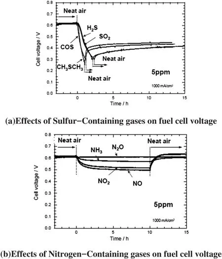
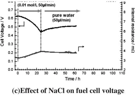
Figure 2:Laboratory tests of effect from contamination on fuel cell voltage[6]
Proof of Concept:Protection of stationary Fuel Cells against Real-Life Contamination
Current research focusses on the transfer of the findings from laboratory tests to real-life environments.The positive effect of adsorptive filter elements on fuel cell degradation was proven in a field trial.In long-term test runs with cyclic NO load,the degradation rate after run-in was cut by almost 50%-from 60µV/h to 32µV/h[7].In a stationary fuel cell system containing two shortstacks,one stack was run without a filter element while a cathode air filter protected the other stack.Both started at the same cell voltage and were operated at 65°C and 400 mA/cm².As shown in Figure 3,the degradation of the unprotected cell was more severe[4].In addition,it was demonstrated through continuous gas measurements that NOxhas a direct influence on the cell voltage under reallife conditions. The detected peaks in pollutant concentration directly lead to a partly reversible voltage drop of the fuel cell voltage.At the end of the test,a voltage difference of 70 mV was observed,equalling approximately 2.2%of the initial voltage,already after 650 hours of operation.The reaction of the filterprotected stack was much less pronounced which proved the functionality of the adsorptive cathode air filter.

Figure 3:Filter performance under real-life conditions[4]
The negative effect of NO on stack voltage is associated with molecular adsorption to the platinum catalyst.As NO binds at the same coordination sites as O2,NO adsorption is slowing down the oxygen reduction reaction.To reverse the negative effect,regeneration strategies can be employed.Tests reveal that a complete regeneration will only take place after several hours of regeneration,and the air has to be free of any NOx.In addition,reduction of NO can create NH4+which in turn is harmful for the Ionomer as it irreversibly occupies active sites for proton transport[7].
2.2 New Insights Into Real-Life Effects On Fuel Cell Durability:ALASKA
The ALASKA Project:Targets and Approach
To investigate the effect of real-life contamination on fuel cell durability in mobile applications,the funded projectALASKA(“Auswertungvon Luftschadstoffszenarien zur Auslegung von Schadgasfiltern und Kathodenregenerationszyklen für Automotive Brennstoffzellen”, support code 03ET6036A)was initiated with the project partners Zentrum fürBrennstoffzellenTechnik (ZBT)GmbH,Forschungszentrum Jülich GmbH,Daimler AG,and MANN+HUMMEL Innenraumfilter GmbH&Co.KG.Oneoftheproject´stargetswasto continue the development of adsorbents against gases poisoning the fuel cell and to gain a better understanding of the necessary capacity and lifetime,with a special focus on the effect of peak concentrations.To gain the necessary data with high precision,a truck equipped with several analysers for the designated harmful gases operated as a mobile lab,measuring the concentration of the harmful substances with high spatiotemporal resolution.

Figure 4:MOBILAB vehicle[8]
A test lap to gather the required data was defined,containing all relevant types of roads,and also a representative height profile.The lap´s length was about 93 km,the road profile is depicted in Figure 5.
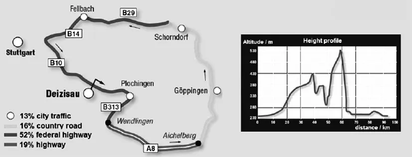
Figure 5:Test lap for measurements of airborne contaminants[8]
After a statistically relevant number of measurements,the typical concentration levels of the target gases were related to the different types of roads.The results of the measurements supported the knowledge-based development of the cathode air filter(Figure 6).Furthermore,the highly sensitive test equipment was being used to investigate the behaviour of the adsorbent under real-life condition to achieve additional performance improvements.
Figure 6:Real-life NOXpollution levels on different road types(adapted from[9])Material Development:Activated Carbon
The contaminants´profiles collected in the ALASKA project showed the need to develop specific adsorbents with tailored selectivity(Figure 7).
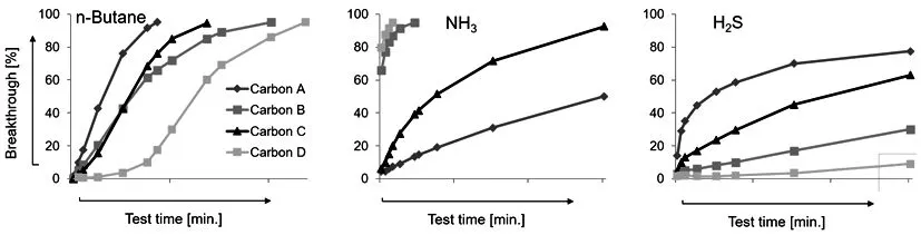
Figure 7:Adsorption profiles of modified activated carbons for different target gases
Activated carbons have proven to be a superior adsorbent choice.Since activated carbons mostly possess non-polar groups on their surfaces,impregnation is important for adsorbing polar gases such as NH3or NOx[10].
Media Development
Adsorbent materials
Bulk measurements(Figure 7)of different activated carbon types show that different treatments are beneficial for some characteristic groups,but lead to a performance drop for other substances.Additionally the separation efficiency for some gases can be lower if other,more strongly bonding molecules,are present in gas mixtures.As protection against a broad range of harmful substances is required,further research led to the development of multilayer media containing these tailored adsorbents in different layers(Figure 8).Special care has to be taken of the rightsequence of layers for fulladsorption performance.Very selective adsorbent should be placed on the upstream side so that the pollutants do not block the binding sites of the less specific ones.

Figure 8:Multilayer design for gas mixtures
By selection of the most specific activated carbons and mixing them in the right proportion,the performance range of the adsorption media can be optimized.If the systemsareoperated in areaswith ahigh sulfur concentrations,e.g.areas with geysers or volcanoes,the share of catalytic activated carbon should be higher.For regions with high NH3levels,media with a higher content of the activated carbon with an acid impregnation yield higher capacity.Through this,multilayer media can be easily tailored for specific requirements.
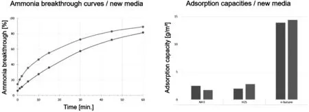
Figure 9:Breakthrough and capacity measurements of tailored filter media
Figure 9 shows the adsorption performance of such media compositions.By using a higher share of the acidimpregnated carbon,the NH3adsorption capacity is enhanced.
Underreal-life operating conditions,the gas concentrations will not be constant,but fluctuating.To analyse the adsorption performance,several filter media samples were tested on-road as part of the ALASKA project (Figure 10),showing excellent separation efficiency even at low concentration levels[11].
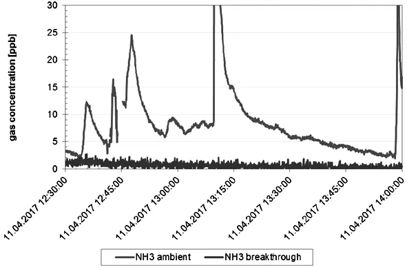
Figure 10:Filter sample NH3separation efficiency under real-life driving conditions
Particle filter media
Salt particles can drain the cell voltage as well.HEPA mediaaccording to EN1822 show particle separation efficiencies of 99.95%at the most penetrating particle size.Therefore,such media protect the cathode againstsodium chloride particles very well.The disadvantage is a potentially fast media clogging,which requires a pre filter in dusty environments.To avoid an extended demand of mounting space,a double layer bellow was developed[11],as shown in Figure 11.
Here,a HEPA media layer is pleated together with a media having a lower efficiency and a higher dust holding capacity.In this structure it is possible to generate a secure protection against fine particles as well as a sufficient dust holding capacity in a minimum mounting space.

Figure 11:Double layer bellow
Filter Element Designs
Laminated media offer the advantage of adsorbent´s immobilization,so negative influence from movement or vibrations of the system can be avoided.Furthermore,the pressure drop can be optimized in relation to the performance density ofthe activated carbon with different design concepts(Figure 12).The trade-off between the performance characteristics (separation efficiency,capacity and pressure loss)on filter element level requires to find the best compromise between packaging constraints and adsorption performance.

Figure 12:Typical air flow/pressure loss profiles for different element designs
A standard pleated filter brings the benefit of a high filtration surface which leads to a lower media velocity and a low pressure drop,especially important for high volume flows,e.g.in FCEV.The open structure of a pleated filter results in a lower performance density.Alternatively,a stacked filter can be applied to gain a higher utilization of the available mounting space.The higher amount of activated carbon in the same volume brings more capacity and a longer contact time with the adsorbent.The higher carbon and performance density leads to a higher pressure loss of the filter element.
For the automotive application investigated in the ALASKA project,a combination of stacked adsorbent layers(Figure 13)with pleated filter media turned out to be the best design option[11].
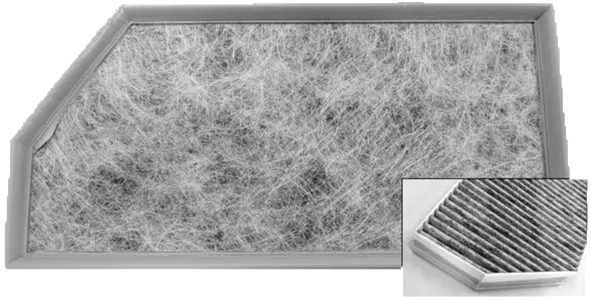
Figure 13:ALASKA filter element
The projectresultsclearly show thatharmful contamination levels of airborne contamination are easily exceeded in selected environments,and that cathode air filters with adsorbent stages are efficient means to reduce degradation rates of LT PEM stacks.
3 CLEANFUELCELLCOOLANT
3.1 Removal of Ions:Ion Exchanger Filter
Scientific background
To remove the heat generated by the fuel cell stack,liquid cooling with water-glycol mixtures is often used.It is crucial to keep the liquid at a very low electric conductivity to avoid electric shorts in the fuel cell stack.During operation,ions can enter the liquid e.g.from metal surfaces of coolant loop components,additives from plastics,and corrosive effects,leading to an increase in electric conductivity.Furthermore,the reactive ions will further propagate corrosion in the cooling circuit,acting as catalysts.Deposits containing different metal ions(Cr,Mn,Fe,Ni and Ca)indicate a degradation of the material´ssurfaceswhich can harm the fuelcell additionally.H2O2can be formed in the fuel cell(Figure 14)and even if the membrane is resistant against it under normal conditions,the presence of metal ions together with H2O2will catalyze the chemical degradation of the membrane.Additionally,almost all cations(except Li+)can replace the protons in the sulfonic acid functions of the membrane,which leads to a decreased protonic conductivity and therefore a performance drop[12].

Figure 14:(l.)Vents corroded in De-Ionized(DI)water(r.)deposits of metal ions[12]
To keep the conductivity low and to protect the coolant loop from accelerated corrosion,ion exchange technology must be applied.
Ion Exchange Filters for Automotive Applications:Material and Product Design
A mixture of strongly acidic and basic resins was developed which maintains its high volumetric capacity even at elevated temperatures,enabling the use in automotive applications.Strongly basic ion exchange resins often show a loss of capacity caused by thermal degradation of the anion-binding groups.This effect is attributed to the“Hofmann Degradation” which eliminatesone methylgroup from the quaternary functional group,yielding a tertiary amine,or even eliminates the whole amine block.Both mechanisms require the presence of OH--anions.For thermal aging tests,the resins where immersed in a water/ethylene glycol mixture and stored for three weeks at 90°C.The samples´remaining ion exchange capacity were measured and compared to the initial values,showing the degree of temperature- induced degradation.Monodisperse styrene-divinylbenzene copolymer(PSDVB) resins with sulfonic acid and quaternary ammonium functions combined good volume-based capacity with a very low degradation after the aging procedure.
To achieve full utilization of the resin mix,an innovative grid structure was developed.The internal lattice structure directs the coolant flow in a way that all resin is used efficiently(Figure 15).In addition,the internal matrix structure keeps the resin beads slightly apart,thus lowering the pressure loss in operation.The internal structure also prevents resin de-mixing caused by vibration in fuel cell systems(Figure 16).
Figure 15:Homogenous flow field at ion exchange filter inlet
Proof of Concept:Breakthrough Curves
As the levels of initial ionic contamination and dragin rates are often not available,typical contamination levels, main contaminants and time- dependent concentration levels were defined,based on literature research,for proof-of-concept testing.The fulfilment of the separation task was proven by breakthrough measurements.The increase in electric conductivity indicates that the resins´capacities are fully spent,and that a filter change is required.

Figure 16:Typical ion exchange filter breakthrough curve
The qualification of the service interval depends on the unique application and is done together with the customer,based on the concrete operation requirements.
3.2 Removal of Particles:Coolant Particle Filter
Problem Description
In addition to ions,the fuel cell coolant can be contaminated by particles.Potential sources for these particles can be the internal surfaces of piping and other components if the parts are not manufactured,stored and assembled in special environments,e.g.in clean rooms.These primary particles can lead to the formation of secondary particles,thus increasing the particle load.Hard particles can lead to several problems,e.g.blocking of narrow coolant channels through agglomeration and inducing wear inside the coolant pump.Both factors can lead to a reduction in cooling efficiency.In contrast to ion exchange filters which are typically installed in a bypass loop,coolant particle filters are placed in the coolant fullflow.This makes it necessary to choose product designs with very low pressure loss at high volume flow.In addition,the material selection for all components is strictly limited to materials which are compatible with the coolant to avoid degradation and leaching of additives which would increase the electric conductivity.
Coolant Particle Filters:Material and Product Design
Often simple meshes are used to hold back particles.These have the disadvantage that large splinters can easily passthrough iforiented in flow direction,perpendicular to the mesh(Figure 17).3D fibre structures overcome this concept´s drawback.

Figure 17:MULTIGRADE media for coolant particle filters
Media with high porosity are applied for low pressure drop.As these have a low thickness,an additional supporting grid must be applied downstream to stabilize the filterpleatsunderhigh volume flow conditions.
ThroughComputationalFluidDynamics(CFD)analysis,a pressure-drop optimized filter design was developed,as shown in Figure 18.

Figure 18:CFD simulation and product design for coolant particle filters
4 SUMMARY
Efficient contaminant removal from cathode air and coolant is required to pave the way to robust and durable,yet affordable fuel cell systems.With ever lower catalyst concentration,the need for a highly efficient protection will increase if the expected system lifetime shall be achieved.Special emphasis will remain on the separation of NH3as it does not only block the catalyst,but also damages the ionomer/membrane material[13].In Selective Catalytic Reduction (SCR)exhaustaftertreatment devices,ammonia slip can occur if an excess of AdBlue/urea solution is sprayed into the system,which will challenge the stack lifetime even more as these systems are expected to strongly penetrate the market.Research on the sensitivity of a LT PEM fuel cell against airborne contamination under real-life automotive conditions led to the knowledge-based development of adsorbents and media for cathode air filters,tailored to effective protection.
To enable the efficient heat removal from the fuel cell stack,the required cleanliness level of the coolant has to be maintained.To protect the fuel cell system from corrosion and electric shorts,ion exchange resins have been developed to keep the electric conductivity and ion contamination in the liquid cooling circuit low.Innovative product features enhance the performance and resin utilization.In addition to ion removal,a coolant particle filter was developed to prevent wear in the coolant pump and blocking of narrow coolant channels.
ABBREVATIONS
ALASKA AuswertungvonLuftschadstoffszenarien zur Auslegung von Schadgasfiltern und Kathodenregenerationszyklen für Automotiv-Brennstoffzellen
BEV Battery Electric Vehicle
CFD Computational Fluid Dynamics
CHP Combined Heat and Power
DI De-Ionized
FCEV Fuel Cell Electric Vehicle
HEPA High Efficiency ParticulateAir filter
LT PEM Low Temperature Proton Exchange Membrane
PS-DVB Styrene-Divinylbenzene copolymer
SCR Selective Catalytic Reduction
Author Introduction of Dr.Michael Harenbrock
Dr.Michael Harenbrock joined MANN+HUMMEL GmbH,a global leader in Filtration,in 1998.He works on fuel cell and battery projects since 2010.In his current position as Principal Expert Electric Mobility,he strategically identifies the need for new filtration solutions for Electric Mobility including Fuel Cell systems through technology and marketscouting,and coordinates all innovation- related activities globally.Networking and collaboration in industry organizations are essential parts of his work as well as presentations in international conferences.
Contact at michael.harenbrock@mann-hummel.com
猜你喜欢
再生资源与循环经济(2022年9期)2022-11-20
机电信息(2022年9期)2022-05-07
军民两用技术与产品(2021年10期)2021-03-16
疯狂英语·新悦读(2020年11期)2020-12-05
汽车文摘(2019年3期)2019-03-04
儿童故事画报·发现号趣味百科(2017年4期)2017-06-30
发明与创新·大科技(2017年5期)2017-05-16
计算机应用(2016年10期)2017-05-12
档案管理(2014年6期)2014-10-30