
Propagation of a Pearcey beam in uniaxial crystals∗
2019-02-25 07:22ChuangjieXu许创杰LudongLin林露东ZhengzhongHuang黄郑重DonglongHe何东龙andDongmeiDeng邓冬梅
Chinese Physics B 2019年2期
Chuangjie Xu(许创杰),Ludong Lin(林露东),Zhengzhong Huang(黄郑重),Donglong He(何东龙),and Dongmei Deng(邓冬梅)
Guangdong Provincial Key Laboratory of Nanophotonic Functional Materials and Devices,South China Normal University,Guangzhou 510631,China
Keywords:crystal optics,diffraction theory,propagation
1.Introduction
In recent years,laser beams with catastrophe functions have inspired considerable theoretical and experimental enthusiasm[1-5]due to the advantage of their plain mathematical representation, flexible generation method,and robust structure,while the Pearcey function,namely the cusp catastrophe,is one kind of catastrophe function.More complicated catastrophe functions or integrals in multi-dimensions,e.g.,swallowtail,butter fly,hyperbolic umbilic,elliptic umbilic,and parabolic umbilic,can be found in catastrophe optics by Berry.[6]
The Pearcey function was recently proven theoretically to be a special solution to the wave equation under the paraxial condition.Soon afterwards,a Pearcey beam was experimentally generated.[2]Several propagation properties,such as auto-focusing,form-invariant,self-healing,and inversion,have been investigated.Moreover,the Pearcey integral has received wide attention in recent decades.In 1999,Kaminski and Paris numerically evaluated and plotted zeros for real values of the arguments of the Pearcey integral.[7]In 2014,Deng et al.have demonstrated a virtual source that yields a family of Pearcey waves.[8]A closed-form expression has been derived for the Pearcey wave that simplifies to a paraxial Pearcey beam in the appropriate limit.In 2015,Kovalev et al.considered the superposition of two paraxial two-dimensional half Pearcey laser beams.[4]In addition to these studies,many other researchers have worked on Pearcey beams.[9-14]
Describing the light propagation in the anisotropic media in both theoretical and applied optics is of interest.[15,16]In reality,crystals play an important part in the design of optical devices,e.g.,polarizers and compensators,because of their ability to affect the polarization state of light.[17]Through uniaxial crystals,the propagation of the Airy beam,[18]the Gaussian beam,[19]and the Bessel beam[20]have been investigated.Yu et al.have studied the analytical propagation of the finite energy Airy-Hermite-Gaussian beam propagating in a uniaxial crystal orthogonal to the optical axis.[21]Their research showed thatthe initialbeam profile of the beam remains nearly invariant for a short propagation distance in the crystal.Zhang et al.have shown that the correlation singularities of a partially coherent Laguerre-Gaussian(LG)electromagnetic beam in a uniaxialcrystalpossess an interesting evolution behavior.[22]It isfound thatthe correlation singularitiesofa partially coherent LG electromagnetic beam in a uniaxial crystal is closely determined by the spatial coherence and mode orders of the beam,and the refractive indexes of the crystal.Other surveys have studied the propagation of beams in the unixial crystal.[23-31]However,to the best of our knowledge,the Pearcey beam only has been investigated in free space.[5,32]Therefore,in the rest of this paper,the propagation of the Pearcey beam in uniaxial crystals is investigated.
2.Propagation of a Pearcey beam in uniaxial crystals orthogonal to the optical axis
In the Cartesian coordinate system,the z axis is taken to be the propagation axis.The optical axis of the uniaxial crystal coincides with the x axis.The input plane is z=0 and the observation plane is z.The ordinary and extraordinary refractive indices of the uniaxial crystal are noand ne,respectively.The relative dielectric tensor of the uniaxial crystal reads as

The electric field distribution of the Pearcey beam in the input plane z=0 reads

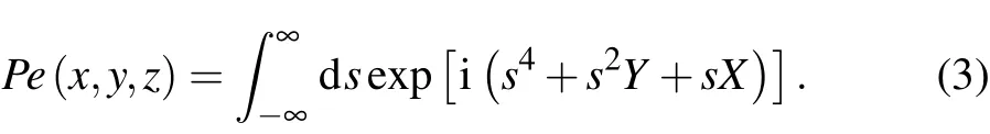
where x′,y′are specified scaling lengths and Pe(x0/x′,y0/y′)is a Pearcey integral which takes the following form
Under the paraxial approximation,the propagation formulas of the Pearcey beams orthogonal to the optical axis can be obtained by[17,18,33]

where k=2π/λ is the wavenumber and λ is the optical wavelength.Substituting Eqs.(1)and(2)into Eqs.(4)and(5),and using the integral formulas

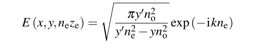
Therefore,the propagating form of the Pearcey beam in uniaxial crystals is
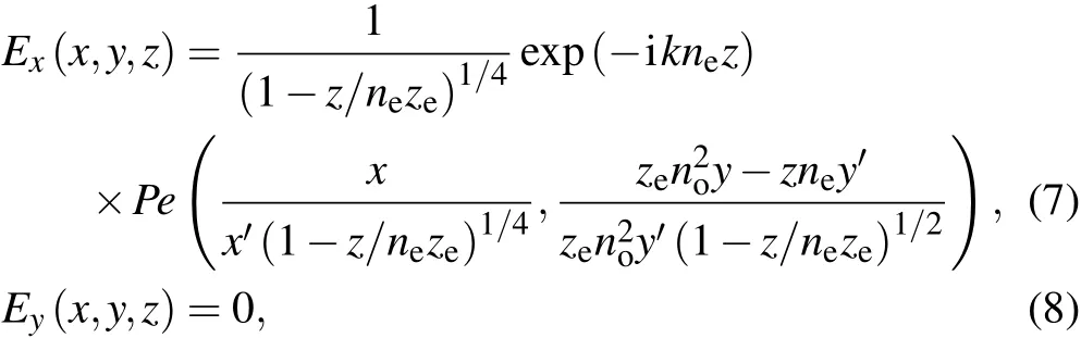
where ze=2ky′2.In this paper,we will study the propagation properties of the Pearcey beam with parameters x′=y′=10-4m.
If we use the following variable substitution
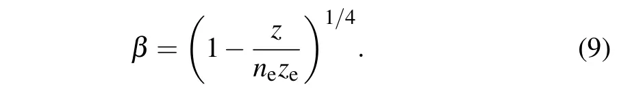
Equation(7)can turn into

Under the condition of ne=no=1,equation(10)reduces to the familiar propagation formula of the Pearcey beam in free space.[2]In addition,from Eq.(10),we can find that,the Pearcey beam,described by a Pearcey function,always keeps the form unchanged when the transmission distance z increases.This shows that the Pearcey beam is still a forminvariant beam even in uniaxial crystals.During propagation,the beam has different spatial scaling in the x-axis and y-axis directions.Moreover,learning from Eq.(10),we note that there is a displacement of the cross section pattern of the Pearcey beam in the y direction when it travels along the z axis and the displacement follows this formula

The function of the Pearcey beam’s cross section point caustic is[34]
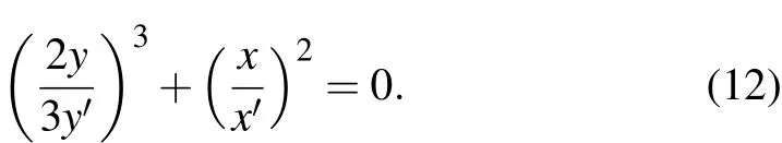
We can obtain the change trend of the Pearcey beam’s point caustic when it propagates in uniaxial crystals from Eqs.(7)and Eq.(12)

3.Numerical calculations and analyses
In this section,we will further investigate the properties of a Pearcey beam in tourmaline and quartz.Tourmaline is a negative crystal while quartz is a positive crystal.The extraordinary refractive index and the ordinary refractive index of the tourmaline are 1.638 and 1.669,respectively,whereas those of the quartz are 1.5534 and 1.5443 under the condition λ=589.3 nm.
3.1.The intensity distribution
Figures 1(a1)-1(a6)represent the contour graph of the intensity distribution of a Pearcey beam propagating in the tourmaline at several observation planes.Figure 1(a7)represents a side-view in the y direction of the paraxial propagation trajectory of a Pearcey beam in the tourmaline.From Figs.1(a1)-1(a6),we can learn that as the transmission distance z increases,the Pearcey beam scales to varying degrees on the cross section.Two ‘arms’of the Pearcey pattern lift upwards and the intensity becomes more and more concentrated when z→neze(1.638zehere).Furthermore,when z=neze,the scaling turns to effectively in finite because of the singularity in both x and y at z=neze,which can be seen from Eq.(10).In the z=nezeplane,the beam is singular,taking the form
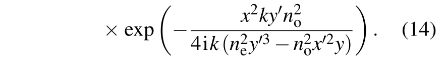
This is an in finitely bright line that almost parallels to the x-axis at y=n2ey′3/n2ox′2.We call this plane(z=neze),the focusing plane.

Fig.1.The contour graph of the intensity distribution and the side-view in the y direction of the paraxial propagation trajectory of a Pearcey beam in the tourmaline;[1(a1)-1(a6)]The contour graph of the intensity distribution:(a1)at z=0.538z e,(a2)at z=1.038z e,(a3)at z=1.538z e,(a4)at z=1.738z e,(a5)at z=2.238z e,(a6)at z=2.738z e,and(a7)the side-view in the y direction of the paraxial propagation trajectory.
In Eq.(13),when z<neze,the caustic line is similar to that of the initial plane,but when z>neze,the denominator turns into an imaginary number so that the caustic line is flipped overalong the x-axis,which we callthe inversion property of the Pearcey beam.This property is well validated and reflected in Figs.1(a1)-1(a6).This means that the positions of the auto-focusing and inversion just relate to the extraordinary refractive index in this case.
From Fig.1(a7),it is noticeable that the Pearcey beam is moving laterally on the y axis when the transmission distance z increases,and the horizontal translation distance and the transmission distance conform to the linear relationship.Furthermore,as the transmission distance z increases,the intensity,at first,gradually becomes stronger,and then weakens.The critical point of this process is z=neze,which means the maximum intensity is at z=neze.
Figures 2(a1)-2(a6)represent the contour graph of the intensity distribution of a Pearcey beam propagating in the quartz at several observation planes.Figure 2(a7)represents a side-view in the y-direction of the paraxial propagation trajectory of a Pearcey beam in the quartz.Comparing Fig.1 to Fig.2,it is obvious that the position of the focusing plane changes because the value of the singularity of the Pearcey beam’s transmission formula changes,which means we could choose the suitable crystals to adjust the positions of autofocusing and inversion.
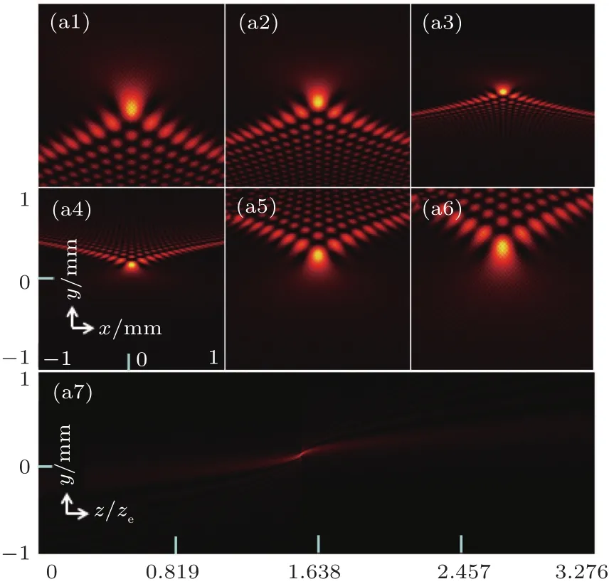
Fig.2.The contour graph of the intensity distribution and the side-view in the y direction of the paraxial propagation trajectory of a Pearcey beam in the quartz;[2(a1)-2(a6)]The contour graph of the intensity distribution:(a1)at z=0.4534z e,(a2)at z=0.9534z e,(a3)at z=0.14534z e,(a4)at z=0.16534z e,(a5)at z=0.21534z e,(a6)at z=0.26534z e,and(a7)the side-view in the y direction of the paraxial propagation trajectory.

Fig.3.The peak intensities of the Pearcey beam propagating in the tourmaline,the quartz and the fictional crystal.
To confirm that the position of auto-focusing just relates to the extraordinary refractive index,we plot the peak intensities of a Pearcey beam propagating in the tourmaline,the quartz and the fictional crystal in Fig.3.The extraordinary refractive index and the ordinary refractive index of the fictional crystal are set to be 0.638 and 1.669 respectively.From Fig.3,we learn that the peak intensities of the Pearcey beam go up dramatically at first and they then go down quickly,which represents the auto-focusing process of the Pearcey beam.And the positions where the peak intensities maximize are the autofocusing planes.We find that the auto-focusing plane of the fictional crystal locates on 0.638zewhereas that of tourmaline locates on 1.638ze.However,the ordinary refractive index of the fictional crystal is the same as that of the tourmaline.This means that the position of the auto-focusing has no contact with the ordinary refractive index of the crystal.We also learn that the peak intensities in the focusing plane are different to each other when the Pearcey beam propagates in different crystals.
3.2.The phase evolution
Figure 4 shows the phase distribution of a Pearcey beam propagating in the tourmaline at several observation planes corresponding to Figs.1(a1)-1(a6).As we mark with ordinal numbersin Fig.3(a1),we can divide the phase distribution into three parts.The first part is the zone surrounded by a parabola(the zone marked with I)and it is next to the second part which consists of two cusp-shaped wings(marked with II),while the last part owns a shape similar to the intensity pattern with two‘arms’,and lots of lobes.From Fig.4,we can learn that,as z→neze,the angle between the two boundaries of zone II decreases while the angle between the two boundaries of zone III increases with the lobes getting denser and denser,which shows that the phase distribution also scales both in x direction and y direction.Besides,the phase pattern inverts when the transmission distance z is bigger than neze.
Fig.4.The phase distribution of a Pearcey beam propagating in the tourmaline at several observation planes corresponding to Figs.1(a1)-1(a6).
3.3.The angular momentum
In this section,we will discuss the properties of the longitudinal normalized angular momentum density of the Pearcey beam propagating in the tourmaline.The study shows that the trapped absorptive particles can spin due to absorption of the angular momentum transferred from the laser beam.[35]Therefore,it is significant to investigate the angular momentum of the Pearcey beam because it can be applied in the optical tweezers technology.[36]The time-averaged AM density J can be written as[37]

Figure 5 shows the angular momentum density(background)and the transverse angular momentum density flow(blue arrows)of a Pearcey beam propagating in the tourmaline at several observation planes.From Fig.5,we note that there are some different properties else about the angular momentum except scaling,auto-focusing and inversion.For example,the angular momentum density hardly distributes on the origin,which causes the lobes near the original point fade out as shown obviously in Fig.5(a2)and Fig.5(a3).The largest direction of the angular momentum density flow tilts up to the right,except that on the line x=0 who points at the positive x-axis direction and parallels to the x axis.As the transmission distance increases,the angle between x axis and the angular momentum density flow on the two ‘arms’at first turns bigger and tends to be 90°,and it then decreases again.

Fig.5.The angular momentum density(background)and the transverse angular momentum density flow(blue arrows)of a Pearcey beam propagating in the tourmaline at several observation planes corresponding to Figs.1(a1)-1(a6).
4.Conclusions
In conclusion,an analytical expression for the propagation of the Pearcey beam in uniaxial crystals orthogonal to the optical axis is derived.We found that the complex amplitude distribution of the Pearcey beam propagating in uniaxial crystal orthogonal to the optical axis always can be described by a Pearcey integral,which theoretically proves that the Pearcey beam is form-invariant during the propagation.Then,we investigate the propagation properties of the Pearcey beam in the tourmaline and the quartz.The result shows that the positions of the auto-focusing and the inversion simply relates to the extraordinary refractive index of the crystals.Besides,the phase distribution and the angular momentum of the Pearcey beam in the tourmaline are also presented.We learn that the angular momentum density hardly distributes on the origin,which causes the lobes near the original point fade out.We believe that the theoretical results presented in this paper would be useful in fields such as micro-imaging and particle manipulation.

- Chinese Physics B的其它文章
- Physics of quantum coherence in spin systems∗
- Recent progress of infrared photodetectors based on lead chalcogenide colloidal quantum dots∗
- Progress in quantum well and quantum cascade infrared photodetectors in SITP∗
- Recent advances in Ga-based solar-blind photodetectors∗
- Development of long-wavelength infrared detector and its space-based application requirements∗
- Transition of photoconductive and photovoltaic operation modes in amorphous Ga2O3-based solar-blind detectors tuned by oxygen vacancies∗