
Investigation of convergent Richtmyer–Meshkov instability at tin/xenon interface with pulsed magnetic driven imploding∗
2019-04-13 01:14ShaolongZhang张绍龙WeiLiu刘伟GuilinWang王贵林ZhengweiZhang章征伟QizhiSun孙奇志ZhaohuiZhang张朝辉JunLi李军YuanChi池原andNanchuanZhang张南川
Chinese Physics B 2019年4期
Shaolong Zhang(张绍龙),Wei Liu(刘伟),Guilin Wang(王贵林),Zhengwei Zhang(章征伟),Qizhi Sun(孙奇志),Zhaohui Zhang(张朝辉),Jun Li(李军),Yuan Chi(池原),and Nanchuan Zhang(张南川)
Institute of Fluid Physics,China Academy of Engineering Physics,Mianyang 621900,China
1.Introduction
When a shock wave passes through an interface of different density materials,disturbances on the interface will experience instability growing which is known as the Richtmyer–Meshkov instability(RMI).Understanding the characteristics of this phenomenon is of great importance in a wide range of scientific and engineering applications among which the instability encountered in inertial confinement fusion(ICF)[1,2]is of great interest.During the past 20 years,considerable amounts of analytical,computational,and experimental works dealt with the planar version of this problem.[3,4]It is benefit to focus on the basic physical process underlying the onset and development of the RMI in simple geometries.Many aspects that affect the RMI behavior have been studied thoroughly under planer configuration,such as the Mach number effects,[5,6]the initial condition effects,[7,8]the Atwood number effects,[9,10]the non-equilibrium characteristics,[11]and so on.However,the imploding of the ICF capsule is in convergent geometry which cannot be investigated by the planner shock wave.[12]In convergent geometry,the RMI differs from the planar case due to the geometrical effects on the instability which has been already recognized and studied by theoretical and numerical methods.[13–19]The experimental study,however,is very limited.To better understand the dynamics of the RMI in convergent geometry and validate models in such configuration,sufficient experimental data are needed.Recently,some researchers are working hard to generate convergent shock wave in shock tubes.[20,21]Holder et al.[22]reported laboratory experiments with a convergent shock tube,using a detonable gas mixture to produce a cylindrically convergent shock.But,such a device is lack of flexibility due to the use of explosive gas.Zhai et al.,[23]Apazidis et al.,[24]and Biamino et al.[25]have experimentally proven the possibility of generating a converging cylindrical shock wave using a conventional shock tube.Most of the experiments studied RMI behavior at gas/gas interface.In this paper,however,we present an alternative way using magnetic driving method to generate convergent shock wave in solid materials and study the RMI of solid/gas interface.
The RM instability phenomena have been thoroughly studied for perfect fluid and gases.Recently,however,the RM instability in solid materials is of growing interest.[18,26–28]In materials with strength,the RMI growth is arrested and stabilized at an amplitude which is in inverse proportion to yield stress Y.[29]Dimonte et al.[30]developed a model for the strength suppression of the RMI that can be used to infer yield strength under shock loading.The RMI has also been adopt to explain the ejecta phenomenon in solid materials.Buttler et al.[31]developed an ejecta source term model that links to the surface perturbations of shocked materials.The RMI evolution was also recommended as an alternative method for evaluating the viscosity of metals.Mikaelian[32]presented an analytical expression for the amplitude of perturbations at the interface of two viscous fluids and found a relation between fluid viscosity and solid strength.Besides the above upcom-ing applications(all of which are in planner regime),the RMI in solid materials under convergent geometry has also critical effect on some engineering applications.[33–35]With the above motivation,a series of experiments were conducted to investigate the convergent RMI phenomenon at the interface between solid tin material and xenon gas in this paper.
2.Methods
In solid materials shock waves are mostly produced by impacting.A variety of driven methods exist,such as projectile of gun type,explosive systems,electrical,electromagnetic,and combined accelerators,devices on the basis of radiation sources(laser radiation and x-radiation,electron,and ion beams,etc.).The method of impactor driven by magnetic field pressure possesses a number of important advantages:
(i)Absence of action of explosive products on the liner means a possibility of its inertial convergence,excludes additional weakly controlled influence on the target, and eliminates a necessity to take this additional action into account during numerical analysis.
(ii)A possibility to set the current pulse of required shape,i.e.,the availability of a broad range of characteristics of the impactor drive,a possibility to obtain different impact velocities.
(iii)High symmetry of loading conditioned by the method of magnetic field generation and absence of additional factors(for example,HE initiation system or non-uniformity of laser radiation).
(iv)“transparency”of the magnetic field allows recording the velocity not only of the inner but also the outer surface of the impactor.
With so much advantages,we choose magnetic-driven liner-on-target method to generate shock waves in the tin material.A general magnetically driven cylinder liner-on-target shock experiment is shown in Fig.1.For an axial directed current I,passing through a liner of radius R,an azimuthal directed magnetic filed B,produces a driving pressure given by

The FP-1 facility(Fig.2)is a pulsed power generator consisting of 216 capacitors located at Institute of Fluid Physics,CAEP.This facility can deliver a peak current of 2 MA to the load with a 7-µs rise time at charging voltage of±20 kV.The details of the facility can be referred to Ref.[36].A φ30-mm inner diameter aluminium liner with 0.5-mm thickness can be driven to a velocity of about 1 km/s(when inner surface diameter is φ18 mm)under this current amplitude.[37,38]Figure 3 shows the load configuration of FP-1 facility for the RMI experiment setup. shock wave is generated by impact of the magnetic driven aluminium liner onto the inner mounted tin target.The inner diameter of the liner is 30 mm and the thickness of the liner is 0.5 mm.The target is a 21-mm inner diameter and 0.7-mm thick tin cylinder.Sinusoidal perturbations with mode number of 21 were machined on the inner surface of the target.Peak to valley amplitude of the perturbation is 0.5 mm.Equation(2)shows the mathematical expression of the perturbation.

The volume between liner and target was pumped to vacuum to avoid retardation from the gases in this zone.Figure 4 shows the cross section of the impactor and target liner.
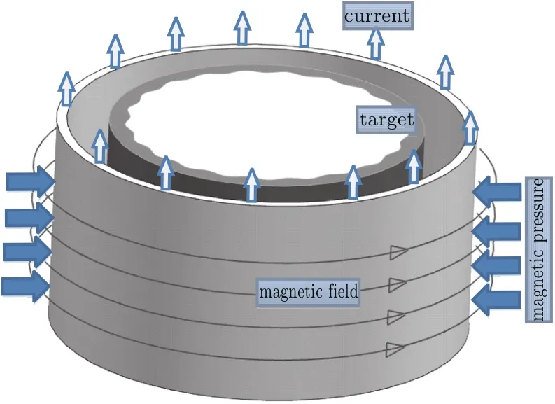
Fig.1.Scheme of liner-impactor driven by magnetic field.
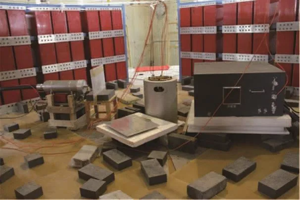
Fig.2.FP-1 facility.
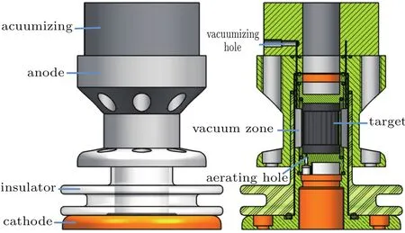
Fig.3.Load configuration of the FP-1 facility.

Fig.4.Cross section of the impactor and target liner.
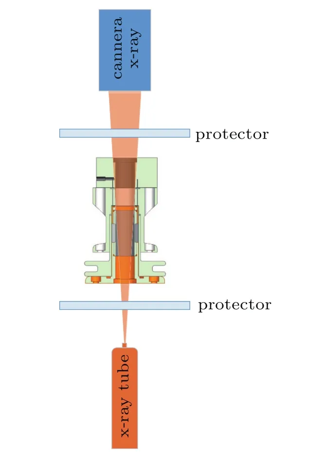
Fig.5.Scheme of the radiography system.
The impacting condition on the tin target was derived from velocity history of the inner surface which were measured with a smooth tin liner before the RMI experiment.A DISAR velocimetry system[39]was used to obtain the velocity history.Rogowski coil was mounted in the load section of the FP-1 facility to collect the current data passing through the liner.A 1D MHD code[40]in cylindrical coordinate regime was used to analysis the liner imploding procedure with the current data as input condition.Inner surface velocity history was compared between the code’s prediction and experiment’s measurement,which will validate the code.Then the impact condition was inferred by the validated code.
Radiography is the main diagnostic for this RMI experiment.It allows the visualization of the disturbance evolution in the otherwise inaccessible target interior during the course of the experiment.The x-ray source size is 1 mm to 1.5 mm with about a 50-ns pulse duration.A Marx bank with charge voltage of 46kV delivered about 450-kV peak voltage to the x-ray diodes which could generate about 5.2×10⁻⁶C/kg x-ray at 1-m distance.X-ray film was collected by a high-resolution CCD camera after a fluorescent screen.Both the x-ray diode and camera were carefully protected from high speed fragments along the axial orientation.Figure 5 shows the arrangement of the radiography system.
3.Results and discussion
3.1.Impact condition
Before the RMI experiment,a velocity measurement experiment was conducted to provide free surface velocity data for 1D MHD code validation and impact condition determination.Figure 6 shows the target configuration used for velocity measurement experiment.Two mini-holes were machined on the target liner which made the DISAR laser probe accessible to the light reflected by the outer impactor liner.Figure 7 shows the velocity measurement results.It can be seen that both the impactor and target liner inner surface velocity history were obtained.The significant jump at 11.5µs in the impactor velocity curve is induced by mass ejection from the mini-hole when the impactor liner contacted with the target liner.The impact velocity is 1 km/s.Figure 8 gave the comparison of the impactor liner velocity between the one-dimensional(1D)MHD code calculation and experimental data which shows excellent agreement.Then,with the validated code we can derive that the impact pressure is 9.75 GPa and shock velocity is 3.22 km/s in the tin target.Under this condition the tin target is still in solid state.
Fig.6.Target configuration for velocity measurement.
Fig.7.Velocity measurement results.

Fig.8.Impactor velocity comparison between 1D MHD simulation and experiment data.
3.2.Repeatability of driving condition
The radiography Marx bank generate only one pulse in one shot which means only one figure could be obtain in one shot.However,to study RMI problem we need a time series pictures.So,sequent shots should be conducted with the same driving condition which demand a perfect discharging repeatability of the facility.The repeatability property of the FP-1 facility were examined and verified before the RMI experiment.Figure 9(a)shows the current comparison between two shots and figure 9(b)shows the impactor velocity comparison between two individual shots.Great repeatability can be inferred from these pictures.
Fig.9.Repeatability property of the FP-1 facility:(a)current comparison and(b)velocity comparison.
3.3.RMI experiment
After the above preparation,a series of RMI experiment were conducted and axial radiography figures(shown in Fig.10)at four individual dynamic times were obtained.Here,the time is relative to the current start time in the circuit.The top two pictures show the initial static frame and the comparison between the 18.3-µs dynamic frame and the initial disturbance profile(the white disturbance curve).From this comparison we can note that the spikes developed from valley zone of the initial disturbance which infer that the disturbance phase already reversed at 18.3µs.

Fig.10.Axial radiography pictures of the RMI experiment.
It is interesting that there exist disturbance growings on both sides of the target although initially the disturbance machined only on the inner surface.We believe that it is belong to the spallation of the target which would induce disturbance on the other side.Figure 11 shows the Radiographic frame of a smooth tin target(without disturbance)from side view.It can be seen clearly that there exist spallation phenomenon in the tin target which confirmed the suppose above.
It can be note from the dynamic frames in Fig.10 that there exists shadow zone ahead and between the disturbance spikes.This phenomenon belongs to the micro-ejection of the tin target surface which is induced by not perfectly smooth surface.The inner surface of the tin target was machined using line-cutting method which limited the surface roughness is about 3.2 micrometer rms.The radius of the interface(spallation)’s and spike peak’s position at each time were summarized in Table 1 excepted for the last two frames whose spikes were contacting each other.
Fig.11.Radial radiography pictures of smooth target.
Table 1.Radii of the spallation,spike peaks and spike amplitude derived from x-ray frames.
3.4.Discussion of strength effect
An analytical model for the disturbance evolution in cylindrical geometry was given by Mikaelian[41]under some assumptions of incompressible,irrotational,and inviscid flows with perturbations in linear regime.The governing equation is shown in below

where R is he cylinder radius,n is the mode number of the perturbation,and A=(ρ2−ρ1)/(ρ2+ρ1)is the Atwood number.A “dot”over a letter refers to the time derivation.Just as what Richtmyer[42]has done,we assume the interface moves with constant velocity(R=R0−∆vt)after shock breaking out which is represented as an impulsive acceleration¨R=∆vδ(t).Then an analytical solution to Eq.(3)can be derived.
From the measurement of the interface radius’s convergence rate in Fig.10,we can obtain the interface moving velocity∆v which is about 800 m/s.Spike amplitude was also measured from Fig.10 which is shown in Fig.12 together with results Eq.(4)and Margolin’s surface area conservation model.It can be noted that Margolin’s surface area conservation model did not capture the phase inverting phenomenon at all and differed a lot from experimental results even qualitatively.It can also be seen from Fig.12 the model of Eq.(3)predicts a higher growing value than experimental results.Main reason for this discrepancy is the absence of strength effect in the model of Eq.(3)which is known as an suppression to the disturbance growing.In fact,the impact pressure in our experiment is much lower than tin’s molten pressure which is above 33 GPa.So,the strength effect must be considered in the model.
Fig.12.Spike amplitude evolution comparison between experiment and analytical model result.
Mikaelian[32]analyzed the viscous effect on shock induced interface instability in planner geometry and derived the governing equation.He found some similarity between metal strength and fluid viscous under the following relation:

where Y is metal strength,µ is fluid viscous,k is wave number of disturbance,and˙η0is the disturbance growth rate immediately after the passage of the shock.Under impulsive acceleration assumption,as Richtmyer[42]showed,˙η0can be written as

With this relation,we can derive the governing equation for disturbance evolution containing strength effect in planner geometry.
Similarly,supposing the strength effect is an intrinsic property of materials which means it has no relationship with configuration,the governing equation in cylinder geometry with strength effect becomes:

Equation(8)was solved numerically(details given in Appendix A),the result is shown in Fig.12.It can be seen clearly in Fig.12 that the spike amplitude growth with strength effect matches well to experimental results which means strength property indeed has critical effect on the disturbance growth rate in our experiment.
4.Conclusion
A series of RMI experiments in solid tin material were initiated on FP-1 facility.Shock wave was generated by magnetic driving method for its advantage in lots of aspects.The 1D MHD code predicted well the impactor velocity which means that the driving condition could be derived from this code and also the desired impact condition could be designed beforehand using this code.With the limitation that the radiography diagnostic could only generate one pulse in one shot,excellent repeatability property of the FP-1 facility guarantees the reliability of the RMI experiment in our study.Five individual times of the disturbance development were obtained by radiography.The spikes of the disturbance existed in both sides of the target which maybe induced by spallation of the tin target on impact.The amplitude of the spikes is derived from the radiographic frames and compared with linear analytical model.The model containing strength effects shows excellent agreement to experimental results.This conclusion makes confidence to the application of using the Richtmyer–Meshkov instability to infer material strength.The results in this paper have validated the magnetic driving method which is appropriate for studying the solid state RMI problem.But lack of sufficient time interval frames makes the results dissatisfy.So,much individual time of the disturbance development will be investigated in the future.
Appendix A:Solving method for Eq.(8)
Under impulse assumption,as Richtmyer[42]showed,the¨R can be written as:
where tsis the time of shock arrival and∆v is the jump in velocity after shock arrival.Substitute this formula into Eq.(8)and integrate over[ts−,ts+].Where ts±are times immediately before and after shock arrival.Considering˙R=0 at this time interval and assuming the strength has no effect during this shock passing process,we can obtain:
where˙η−and˙η+are the growth rates immediately before and after the passage of the shock,ηsis the amplitude at shock arrival time,and Rsis the radius at that time.For an initially stationary interface we have η˙−=0,ηs=η0,andRs=R0.Assuming a shock arriving at ts=0,then equation(8)becomes the following initial value problem

Equation(A1)can be solved numerically using Runge–Kutta method.We choose strength parameter of tin as the static one Y=12 MPa,and ρ0=7.28 g/cm3,A=1, ∆v=800 m/s,n=21.
Acknowledgment
The authors would thank Yuesong Jia,Xiaoming Zhao and Weidong Qin for their kindly help to maintain the FP-1 facility.The authors would also thank Yang Zhang,Zheng Fu and Lili Wang for their fruitful discussion of the experiment results.
[1]Dittrich T R,Hammel B A,Keane C J,McEachern R,Turner R E,Haan S W and Suter L J 1994 Phys.Rev.Lett.73 2324
[2]Clark D S,Haan S W,Cook A W,Edwards M J,Hammel B A,Koning J M and Marinak M M 2011 Phys.Plasmas 18 082701
[3]Brouillette M 2002 Ann.Rev.Fluid Mech.34 445
[4]Prestridge K,Orlicz G,Balasubramanian S and Balakumar B J 2013 Phil.Trans.R Soc.A 37 20120165
[5]Orlicz G C,Balakumar B J,Tomkins C D and Prestridge K P 2009 Phys.Fluids 21 064102
[6]Yang J,Wan Z H,Wang B F and Sun D J 2015 Chin.Phys.Lett.32 034701
[7]Thornber B,Drikakis D,Youngs D L and Williams R J R 2010 J.Fluid Mech.654 99
[8]Mariani C,Vandenboomgaerde M,Lourdan G,Souffland D and Houas L 2008 Phys.Rev.Lett.100 254503
[9]Tao Y S,Wang L F,Ye W H,Zhang G C,Zhang J C and Li Y J 2012 Acta Phys.Sin.61 075207(in Chinese)
[10]Jourdan G and Houas L 2005 Phys.Rev.Lett.95 204502
[11]Chen F,Xu A G and Zhang G C 2018 Phys.Fluids 30 102105
[12]Wang L F,Ye W H,He X T,Wu J F,Fan Z F,Xue C,Guo H Y,Miao W Y,Yuan Y T,Dong J Q,Jia G,Zhang J,Li Y J,Liu J,Wang M,Ding Y K,and Zhang W Y 2017 Sci.China-Phys.Mech.Astron.60 055201
[13]Zhang Q and Graham M J 1997 Phys.Rev.Lett.79 2674
[14]Matsuoka C and Nishihara K 2006 Phys.Rev.E 74 066303
[15]Tian B L,Fu D X and Ma Y W 2006 Acta Mech.Sin.22 9
[16]Lombardini M 2008 Richtmyer Meshkov Instability in Converging Geometries,Ph.D.Dissertation(Pasadena:California Institute of Technology)
[17]Guo H Y,Yu X J,Wang L F,Ye W H,Wu J F and Li Y J 2014 Chin.Phys.Lett.31 044702
[18]Liu J,Feng Q J and Zhou H B 2014 Acta Phys.Sin.63 155201(in Chinese)
[19]Liang Y,Guan B,Zhai Z G and Luo X S 2017 Acta Phys.Sin.66 064701(in Chinese)
[20]Biamino L,Jourdan G,Mariani C,Houas L,Vandenboomgaerde M and Souffland D 2015 Exp.Fluids 56 26
[21]Luo X S,Ding J C,Wang M H,Zhai Z G and Si T 2015 Phys.Fluids 27 091702
[22]Holder D A,Smith A V,Barton C J and Youngs D L 2003 Laser Part.Beams 21 403
[23]Zhai Z G,Si T,Luo X S,Yang J M,Liu C L,Tan D W and Zou L Y 2012 Phys.Fluids 24 026101
[24]Apazidis N,Kjellander and Tillmark N 2013 Shock Waves 23 361
[25]Biamino L,Jourdan G,Mariani C,Houas L,Vandenboomgaerde M and Souffland D 2014 J.Fluids Eng.136 091204
[26]Piriz A R,L´oez Cela J J and Tahir N A 2009 Nucl.Instrum.Method A 606 139
[27]Piriz A R,L´oez Cela J J and Tahir N A 2009 Phys.Rev.E 80 046305
[28]Yin J W,Pan H,Wu Z H,Hao P C,Duan Z P and Hu X M 2017 Acta Phys.Sin.66 204701(in Chinese)
[29]Piriz A R,L´oez Cela J J,Tahir N A and Hoffmann D H H 2008 Phys.Rev.E 78 056401
[30]Dimonte G,Terrones G,Cherne F J,Germann T C,Dupont V,Kadau K,Buttler W T,Oro D M,Morris C and Preston D L 2011 Phys.Rev.Lett.107 264502
[31]Buttler W T,Or´o D M,Preston D L,Mikaelian K O,Cherne F J,Hixson R S,Mariam F G,Morris C,Stone J B,Terrones G and Tupa D 2012 J.Fluid Mech.703 60
[32]Mikaelian K O 2013 Phys.Rev.E 87 031003
[33]Rousculp C L,Oro D M,Margolin L G,Griego J R,Reinovsky R E and Turchi P J 2015 Tech.Rep.LA-UR-15-26264,Los Alamos National Laboratory
[34]Rousculp C L,Oro D M,Griego J R,Turchi P J,Reinovsky R E,Bradley J T,Cheng B,Freeman M S and Patten A R 2016 Tech.Rep.LA-UR-16-21901,Los Alamos National Laboratory
[35]Rousculp C L,Oro D M,Griego J R,Patten A R,Neukirch L P,Reinovsky R E,Turchi P J,Bradley J T,Reass W A,Fierro F,Saunders A,Mariam F G,Freeman M S,Cheng B and Tang Z 2017 Tech.Rep.LA-UR-17-23974,Los Alamos National Laboratory
[36]Yang L B,Sun C W,Liao H D and Hu X J 2002 High Power Laser and Particle Beams 14 767
[37]Zhang Z W,Wei Y,Sun Q Z,Liu W,Zhao X M,Zhang Z H,Wang G L,Guo S and Xie W P 2016 High Power Laser and Particle Beams 28 045017(in Chinese)
[38]Zhang S L,Zhang Z W,Sun Q Z,Liu W,Zhao X M,Zhang Z H,Wang G L and Jia Y S 2017 High Power Laser and Particle Beams 29 105002(in Chinese)
[39]Weng J D,Tan H,Wang X,Ma Y,Hu S L and Wang X S 2006 Appl.Phys.Lett.89 111101
[40]Zhang Y,Dai Z H,Sun Q Z,Zhang Z W,Sun H Q,Wang P,Ding N,Xue C,Wang G Q,Shen Z J,Li X and Wang J G 2018 Acta Phys.Sin.67 080701(in Chinese)
[41]Mikaelian K O 2005 Phys.Fluid 17 094105
[42]Richtmyer R D 1960 Commun.Pure Appl.Math.13 297
猜你喜欢
当代党员(2022年9期)2022-05-20
语数外学习·高中版中旬(2021年12期)2021-03-09
摄影与摄像(2020年11期)2020-09-10
科学导报(2019年23期)2019-09-03
小天使·五年级语数英综合(2019年8期)2019-08-27
中华书画家(2018年1期)2018-01-14
湖南行政学院学报(2017年3期)2017-06-07
艺术品鉴(见今)(2017年3期)2017-05-15
湖湘论坛(2017年2期)2017-03-20
散文百家(2016年2期)2016-12-08

- Chinese Physics B的其它文章
- Entangled multi-knot lattice model of anyon current∗
- Miniature quad-channel spin-exchange relaxation-free magnetometer for magnetoencephalography∗
- Observing the steady-state visual evoked potentials with a compact quad-channel spin exchange relaxation-free magnetometer∗
- Quantum interferometry via a coherent state mixed with a squeezed number state∗
- Cavity enhanced measurement of trap frequency in an optical dipole trap∗
- 7.6-W diode-pumped femtosecond Yb:KGW laser∗